1983 FIAT UNO weight
[x] Cancel search: weightPage 2 of 303
Contents
LIVING WITH YOUR FIAT UNO
IntroductionPage 0•4
Safety First!Page 0•5
General dimensions, weights and capacities Page0•6
Roadside Repairs
Jump startingPage0•7
Jacking, towing and wheel changing Page0•8
Identifying leaksPage0•9
Routine Maintenance and Servicing
Maintenance schedule (also see Chapter 13)Page0•10
Recommended Lubricants and Fluids Page0•13
Conversion factorsPage0•14
Page 4 of 303
The Fiat Uno is a well designed and
constructed car having an excellent
power-to-weight ratio.
The car is very economical, but still offers
good performance with excellent body interior
space.
Attractive features include the options
available for four- or five-speeds or three- or
five-door bodywork.
All essential accessories, except a radio,
are fitted as standard and a sunroof is
optionally available.
From the home mechanic’s point of view all
repair and servicing operations are straight-
forward without the need for special tools.
Spare parts are immediately available at
moderate cost.
Acknowledgements
Thanks are due to Champion Spark Plug
who supplied the illustrations showing spark
plug conditions. Certain other illustrations are
the copyright of the Fiat Motor Company (UK)
Limited and are used with their permission.
Thanks are also due to Sykes-Pickavant
Limited, who provided some of the
workshop tools, and to all those people at
Sparkford who helped in the production of
this manual.
We take great pride in the accuracy of
information given in this manual, but
vehicle manufacturers make alterations
and design changes during the production
run of a particular vehicle of which they do
not inform us, No liability can be accepted
by the authors or publishers for loss,
damage or injury caused by any errors in,
or omissions from, the information given.
0•4Introduction
Introduction to the
Fiat Uno
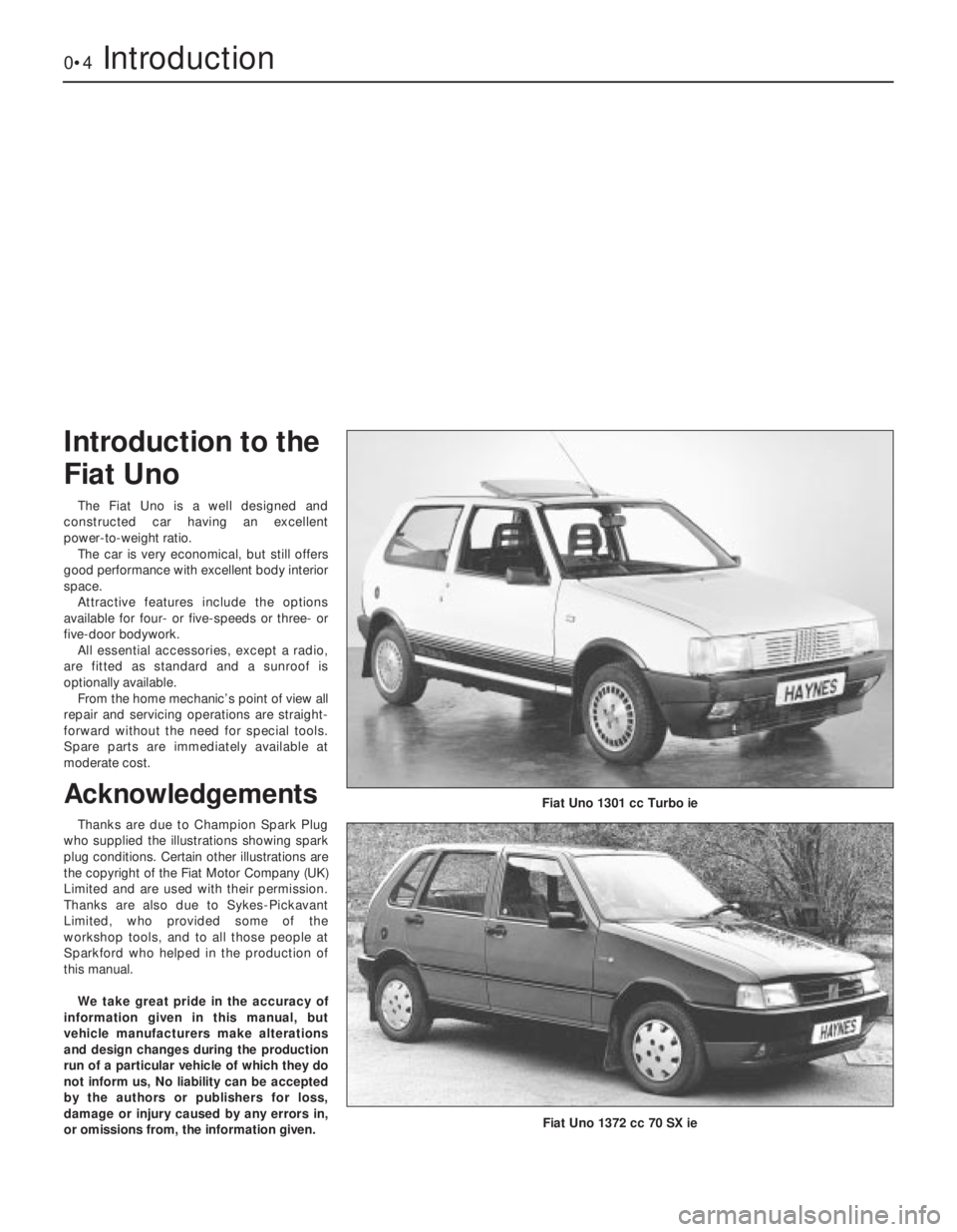
Fiat Uno 1301 cc Turbo ie
Fiat Uno 1372 cc 70 SX ie
Page 6 of 303
0•6General dimensions, weights and capacities
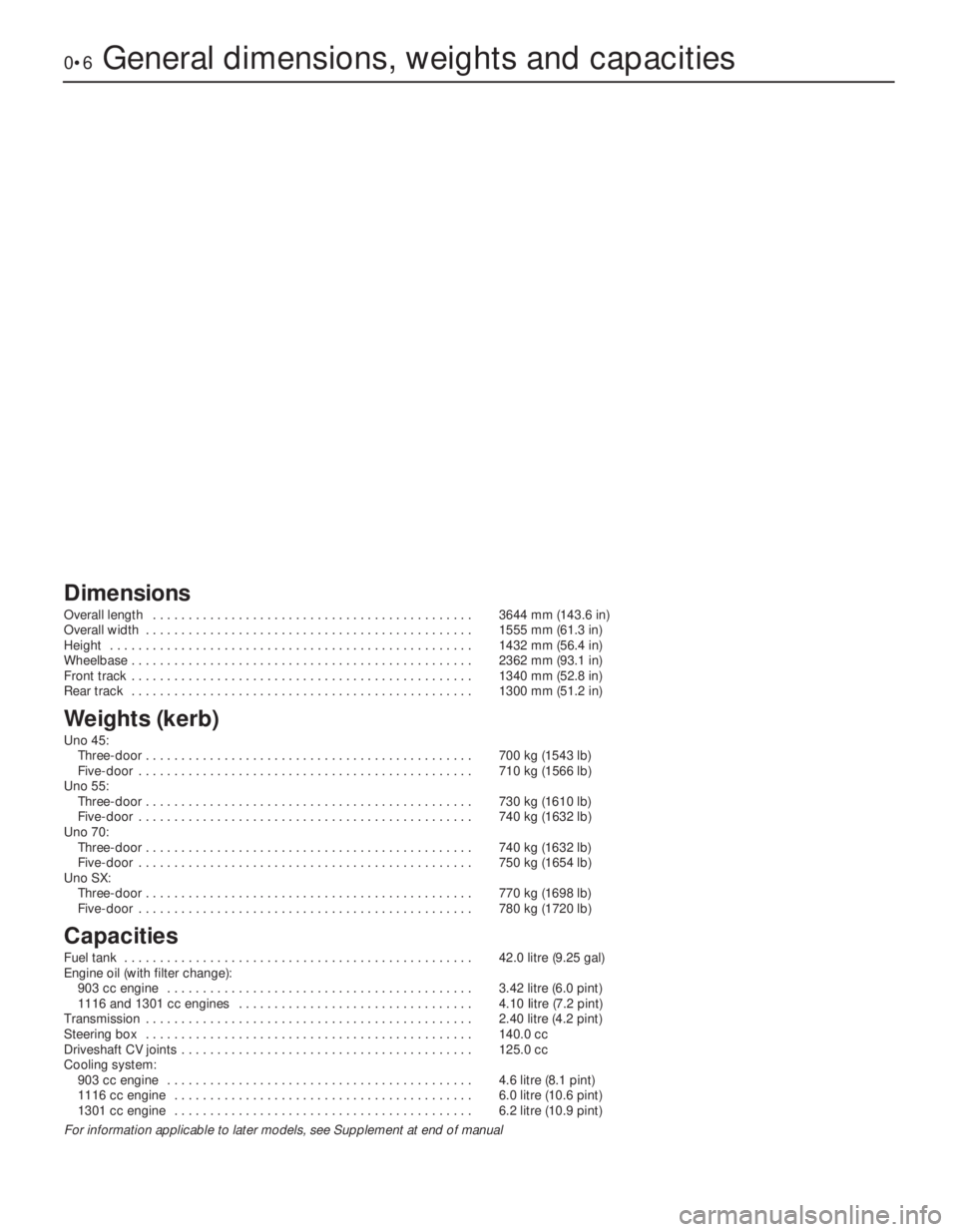
Dimensions
Overall length . . . . . . . . . . . . . . . . . . . . . . . . . . . . . . . . . . . . . . . . . . . . . 3644 mm (143.6 in)
Overall width . . . . . . . . . . . . . . . . . . . . . . . . . . . . . . . . . . . . . . . . . . . . . . 1555 mm (61.3 in)
Height . . . . . . . . . . . . . . . . . . . . . . . . . . . . . . . . . . . . . . . . . . . . . . . . . . . 1432 mm (56.4 in)
Wheelbase . . . . . . . . . . . . . . . . . . . . . . . . . . . . . . . . . . . . . . . . . . . . . . . . 2362 mm (93.1 in)
Front track . . . . . . . . . . . . . . . . . . . . . . . . . . . . . . . . . . . . . . . . . . . . . . . . 1340 mm (52.8 in)
Rear track . . . . . . . . . . . . . . . . . . . . . . . . . . . . . . . . . . . . . . . . . . . . . . . . 1300 mm (51.2 in)
Weights (kerb)
Uno 45:
Three-door . . . . . . . . . . . . . . . . . . . . . . . . . . . . . . . . . . . . . . . . . . . . . . 700 kg (1543 lb)
Five-door . . . . . . . . . . . . . . . . . . . . . . . . . . . . . . . . . . . . . . . . . . . . . . . 710 kg (1566 lb)
Uno 55:
Three-door . . . . . . . . . . . . . . . . . . . . . . . . . . . . . . . . . . . . . . . . . . . . . . 730 kg (1610 lb)
Five-door . . . . . . . . . . . . . . . . . . . . . . . . . . . . . . . . . . . . . . . . . . . . . . . 740 kg (1632 lb)
Uno 70:
Three-door . . . . . . . . . . . . . . . . . . . . . . . . . . . . . . . . . . . . . . . . . . . . . . 740 kg (1632 lb)
Five-door . . . . . . . . . . . . . . . . . . . . . . . . . . . . . . . . . . . . . . . . . . . . . . . 750 kg (1654 lb)
Uno SX:
Three-door . . . . . . . . . . . . . . . . . . . . . . . . . . . . . . . . . . . . . . . . . . . . . . 770 kg (1698 lb)
Five-door . . . . . . . . . . . . . . . . . . . . . . . . . . . . . . . . . . . . . . . . . . . . . . . 780 kg (1720 lb)
Capacities
Fuel tank . . . . . . . . . . . . . . . . . . . . . . . . . . . . . . . . . . . . . . . . . . . . . . . . . 42.0 litre (9.25 gal)
Engine oil (with filter change):
903 cc engine . . . . . . . . . . . . . . . . . . . . . . . . . . . . . . . . . . . . . . . . . . . 3.42 litre (6.0 pint)
1116 and 1301 cc engines . . . . . . . . . . . . . . . . . . . . . . . . . . . . . . . . . 4.10 Iitre (7.2 pint)
Transmission . . . . . . . . . . . . . . . . . . . . . . . . . . . . . . . . . . . . . . . . . . . . . . 2.40 litre (4.2 pint)
Steering box . . . . . . . . . . . . . . . . . . . . . . . . . . . . . . . . . . . . . . . . . . . . . . 140.0 cc
Driveshaft CV joints . . . . . . . . . . . . . . . . . . . . . . . . . . . . . . . . . . . . . . . . . 125.0 cc
Cooling system:
903 cc engine . . . . . . . . . . . . . . . . . . . . . . . . . . . . . . . . . . . . . . . . . . . 4.6 litre (8.1 pint)
1116 cc engine . . . . . . . . . . . . . . . . . . . . . . . . . . . . . . . . . . . . . . . . . . 6.0 litre (10.6 pint)
1301 cc engine . . . . . . . . . . . . . . . . . . . . . . . . . . . . . . . . . . . . . . . . . . 6.2 litre (10.9 pint)
For information applicable to later models, see Supplement at end of manual
Page 14 of 303
0•14Conversion Factors
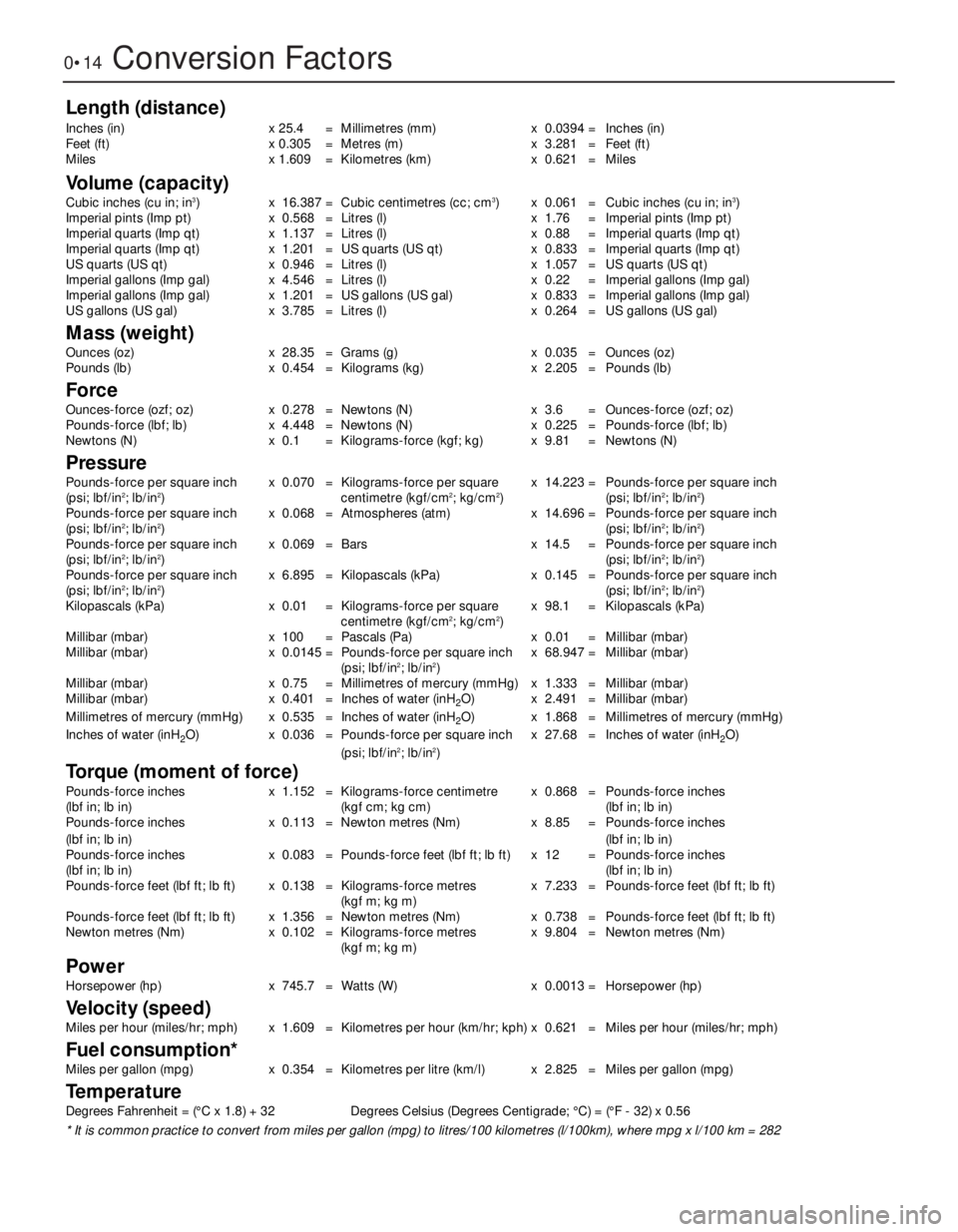
Length (distance)
Inches (in) x 25.4 = Millimetres (mm) x 0.0394 = Inches (in)
Feet (ft) x 0.305 = Metres (m) x 3.281 = Feet (ft)
Miles x 1.609 = Kilometres (km) x 0.621 = Miles
Volume (capacity)
Cubic inches (cu in; in3) x 16.387 = Cubic centimetres (cc; cm3) x 0.061 = Cubic inches (cu in; in3)
Imperial pints (Imp pt) x 0.568 = Litres (l) x 1.76 = Imperial pints (Imp pt)
Imperial quarts (Imp qt) x 1.137 = Litres (l) x 0.88 = Imperial quarts (Imp qt)
Imperial quarts (Imp qt) x 1.201 = US quarts (US qt) x 0.833 = Imperial quarts (Imp qt)
US quarts (US qt) x 0.946 = Litres (l) x 1.057 = US quarts (US qt)
Imperial gallons (Imp gal) x 4.546 = Litres (l) x 0.22 = Imperial gallons (Imp gal)
Imperial gallons (Imp gal) x 1.201 = US gallons (US gal) x 0.833 = Imperial gallons (Imp gal)
US gallons (US gal) x 3.785 = Litres (l) x 0.264 = US gallons (US gal)
Mass (weight)
Ounces (oz) x 28.35 = Grams (g) x 0.035 = Ounces (oz)
Pounds (lb) x 0.454 = Kilograms (kg) x 2.205 = Pounds (lb)
Force
Ounces-force (ozf; oz) x 0.278 = Newtons (N) x 3.6 = Ounces-force (ozf; oz)
Pounds-force (lbf; lb) x 4.448 = Newtons (N) x 0.225 = Pounds-force (lbf; lb)
Newtons (N) x 0.1 = Kilograms-force (kgf; kg) x 9.81 = Newtons (N)
Pressure
Pounds-force per square inch x 0.070 = Kilograms-force per square x 14.223 = Pounds-force per square inch
(psi; lbf/in2; lb/in2) centimetre (kgf/cm2; kg/cm2) (psi; lbf/in2; lb/in2)
Pounds-force per square inch x 0.068 = Atmospheres (atm) x 14.696 = Pounds-force per square inch
(psi; lbf/in
2; lb/in2)(psi; lbf/in2; lb/in2)
Pounds-force per square inch x 0.069 = Bars x 14.5 = Pounds-force per square inch
(psi; lbf/in
2; lb/in2)(psi; lbf/in2; lb/in2)
Pounds-force per square inch x 6.895 = Kilopascals (kPa) x 0.145 = Pounds-force per square inch
(psi; lbf/in
2; lb/in2)(psi; lbf/in2; lb/in2)
Kilopascals (kPa) x 0.01 = Kilograms-force per square x 98.1 = Kilopascals (kPa)
centimetre (kgf/cm
2; kg/cm2)
Millibar (mbar) x 100 = Pascals (Pa) x 0.01 = Millibar (mbar)
Millibar (mbar) x 0.0145 = Pounds-force per square inch x 68.947 = Millibar (mbar)
(psi; lbf/in
2; lb/in2)
Millibar (mbar) x 0.75 = Millimetres of mercury (mmHg) x 1.333 = Millibar (mbar)
Millibar (mbar) x 0.401 = Inches of water (inH
2O) x 2.491 = Millibar (mbar)
Millimetres of mercury (mmHg) x 0.535 = Inches of water (inH
2O) x 1.868 = Millimetres of mercury (mmHg)
Inches of water (inH
2O) x 0.036 = Pounds-force per square inch x 27.68 = Inches of water (inH2O)
(psi; lbf/in2; lb/in2)
Torque (moment of force)
Pounds-force inches x 1.152 = Kilograms-force centimetre x 0.868 = Pounds-force inches
(lbf in; lb in) (kgf cm; kg cm) (lbf in; lb in)
Pounds-force inches x 0.113 = Newton metres (Nm) x 8.85 = Pounds-force inches
(lbf in; lb in)(lbf in; lb in)
Pounds-force inches x 0.083 = Pounds-force feet (lbf ft; lb ft) x 12 = Pounds-force inches
(lbf in; lb in)(lbf in; lb in)
Pounds-force feet (lbf ft; lb ft) x 0.138 = Kilograms-force metres x 7.233 = Pounds-force feet (lbf ft; lb ft)
(kgf m; kg m)
Pounds-force feet (lbf ft; lb ft) x 1.356 = Newton metres (Nm) x 0.738 = Pounds-force feet (lbf ft; lb ft)
Newton metres (Nm) x 0.102 = Kilograms-force metres x 9.804 = Newton metres (Nm)
(kgf m; kg m)
Power
Horsepower (hp) x 745.7 = Watts (W) x 0.0013 = Horsepower (hp)
Velocity (speed)
Miles per hour (miles/hr; mph) x 1.609 = Kilometres per hour (km/hr; kph) x 0.621 = Miles per hour (miles/hr; mph)
Fuel consumption*
Miles per gallon (mpg) x 0.354 = Kilometres per litre (km/l) x 2.825 = Miles per gallon (mpg)
Temperature
Degrees Fahrenheit = (°C x 1.8) + 32 Degrees Celsius (Degrees Centigrade; °C) = (°F - 32) x 0.56
* It is common practice to convert from miles per gallon (mpg) to litres/100 kilometres (l/100km), where mpg x l/100 km = 282
Page 27 of 303
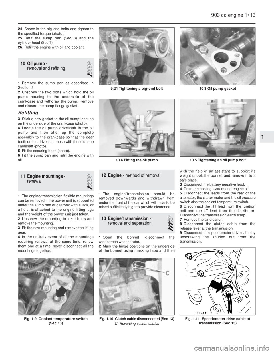
24Screw in the big-end bolts and tighten to
the specified torque (photo).
25Refit the sump pan (Sec 8) and the
cylinder head (Sec 7).
26Refill the engine with oil and coolant.
10 Oil pump-
removal and refitting
1
1Remove the sump pan as described in
Section 8.
2Unscrew the two bolts which hold the oil
pump housing to the underside of the
crankcase and withdraw the pump. Remove
and discard the pump flange gasket.
Refitting
3Stick a new gasket to the oil pump location
on the underside of the crankcase (photo).
4Locate the oil pump driveshaft in the oil
pump and then offer up the complete
assembly to the crankcase so that the gear
teeth on the driveshaft mesh with those on the
camshaft (photo).
5Fit the securing bolts (photo).
6Fit the sump pan and refill the engine with
oil.
11 Engine mountings-
renewal
1
1The engine/transmission flexible mountings
can be removed if the power unit is supported
under the sump pan or gearbox with a jack, or
a hoist is attached to the engine lifting lugs
and the weight of the power unit just taken.
2Unscrew the mounting bracket bolts and
remove the mounting.
3Fit the new mounting and remove the lifting
gear.
4In the unlikely event of all the mountings
requiring renewal at the same time, renew
them one at a time, never disconnect all the
mountings together.
12 Engine- method of removal
1The engine/transmission should be
removed downwards and withdrawn from
under the front of the car which will have to be
raised sufficiently high to provide clearance.
13 Engine/transmission-
removal and separation
3
1Open the bonnet, disconnect the
windscreen washer tube.
2Mark the hinge positions on the underside
of the bonnet using masking tape and thenwith the help of an assistant to support its
weight unbolt the bonnet and remove it to a
safe place.
3Disconnect the battery negative lead.
4Drain the cooling system and engine oil.
5Disconnect the leads from the rear of the
alternator, the starter motor and the oil pressure
switch also the coolant temperature switch.
6Disconnect the HT lead from the ignition
coil and the LT lead from the distributor.
Disconnect the transmission earth strap.
7Remove the air cleaner.
8Disconnect the clutch cable from the
release lever at the transmission.
9Disconnect the speedometer drive cable by
unscrewing the knurled nut from the
transmission.
903 cc engine 1•13
10.3 Oil pump gasket
10.4 Fitting the oil pump10.5 Tightening an oil pump bolt
9.24 Tightening a big-end bolt
Fig. 1.11 Speedometer drive cable at
transmission (Sec 13)Fig. 1.10 Clutch cable disconnected (Sec 13)
C Reversing switch cablesFig. 1.9 Coolant temperature switch
(Sec 13)
1
Page 29 of 303
31Support the weight of the transmission
and withdraw it in a straight line from the
engine.
14 Engine- dismantling (general)
1Stand the engine on a strong bench at a
suitable working height. Failing this, it can be
dismantled on the floor, but at least stand it
on a sheet of hardboard.
2During the dismantling process, the
greatest care should be taken to keep the
exposed parts free from dirt. As the engine is
stripped, clean each part in a bath of paraffin.
3Never immerse parts with oilways in
paraffin, e.g. the crankshaft, but to clean,
wipe down carefully with a paraffin dampened
rag. Oilways can be cleaned out with a piece
of wire. If an air line is available, all parts can
be blown dry and the oilways blown through
as an added precaution.
4Re-use of old gaskets is false economy and
can give rise to oil and water leaks, if nothing
worse. To avoid the possibility of trouble after
the engine has been reassembled always use
new gaskets throughout.
5To strip the engine, it is best to work from
the top downwards. The engine oil sump
provides a firm base on which the engine can
be supported in an upright position. When the
stage is reached where the pistons are to be
removed, turn the engine on its side. Turn the
block upside down to remove the crankshaft.
6Wherever possible, replace nuts, bolts and
washers finger-tight from wherever they were
removed. This helps avoid later loss and
muddle. If they cannot be replaced then lay
them out in such a fashion that it is clear from
where they came.
15 Engine- removing ancillary
components
1Before dismantling the engine, remove the
engine ancillary components.
Carburettor (Chapter 3)
Thermostat housing (Chapter 2)
Alternator (Chapter 9)
Coolant pump (Chapter 2)
Distributor (Chapter 4)
Exhaust manifold (Chapter 3)
Fuel pump (Chapter 3)
Oil filter cartridge (Section 2 this Chapter)
Clutch (Chapter 5)
903 cc engine 1•15
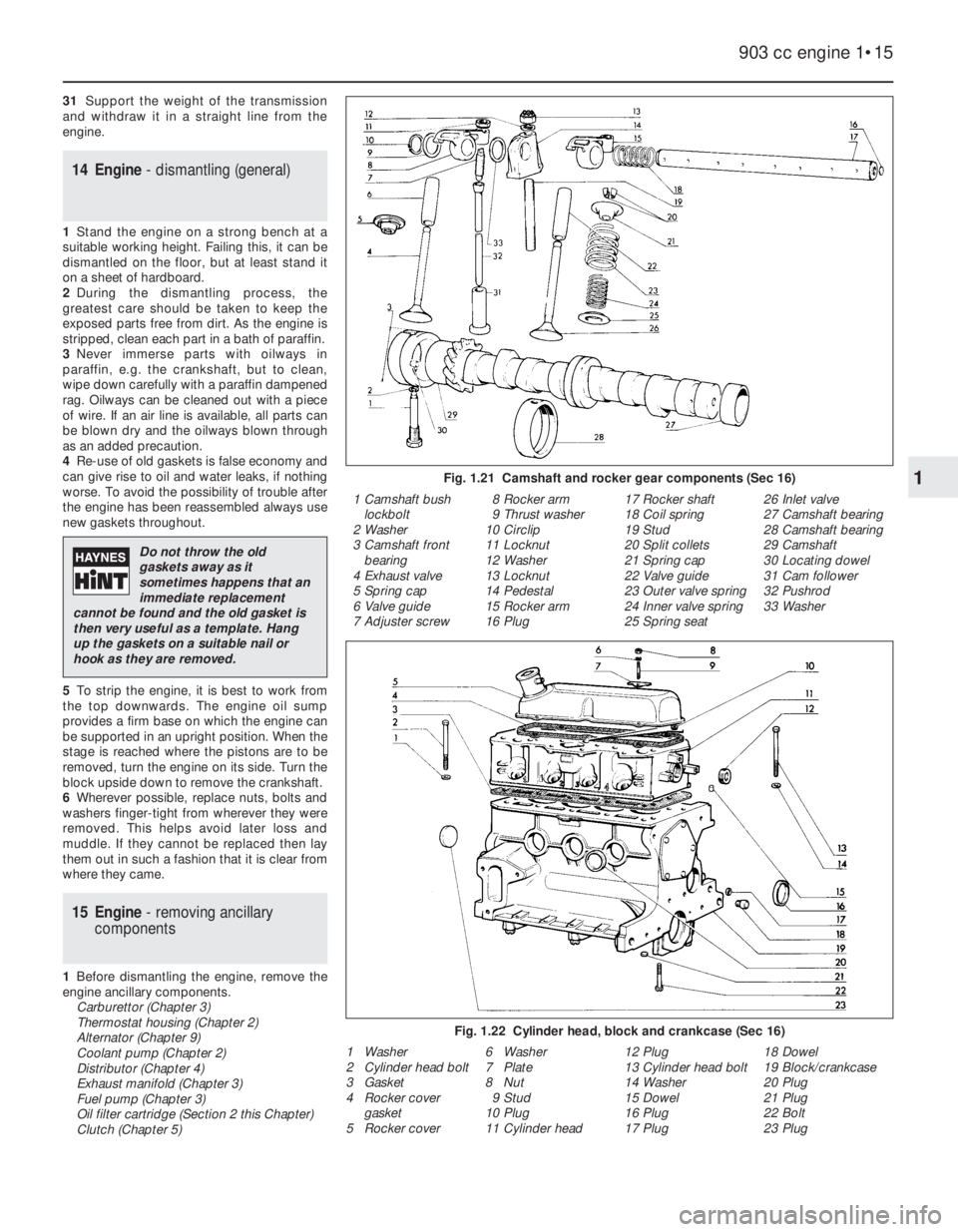
Fig. 1.21 Camshaft and rocker gear components (Sec 16)
Fig. 1.22 Cylinder head, block and crankcase (Sec 16)
1 Camshaft bush
lockbolt
2 Washer
3 Camshaft front
bearing
4 Exhaust valve
5 Spring cap
6 Valve guide
7 Adjuster screw8 Rocker arm
9 Thrust washer
10 Circlip
11 Locknut
12 Washer
13 Locknut
14 Pedestal
15 Rocker arm
16 Plug17 Rocker shaft
18 Coil spring
19 Stud
20 Split collets
21 Spring cap
22 Valve guide
23 Outer valve spring
24 Inner valve spring
25 Spring seat26 Inlet valve
27 Camshaft bearing
28 Camshaft bearing
29 Camshaft
30 Locating dowel
31 Cam follower
32 Pushrod
33 Washer
1 Washer
2 Cylinder head bolt
3 Gasket
4 Rocker cover
gasket
5 Rocker cover6 Washer
7 Plate
8 Nut
9 Stud
10 Plug
11 Cylinder head12 Plug
13 Cylinder head bolt
14 Washer
15 Dowel
16 Plug
17 Plug18 Dowel
19 Block/crankcase
20 Plug
21 Plug
22 Bolt
23 Plug
1
Do not throw the old
gaskets away as it
sometimes happens that an
immediate replacement
cannot be found and the old gasket is
then very useful as a template. Hang
up the gaskets on a suitable nail or
hook as they are removed.
Page 30 of 303

16 Engine-
complete dismantling
3
1Unbolt and remove the rocker cover.
2Unscrew the rocker pedestal securing nuts
and lift away the rocker assembly.
3Remove the pushrods, keeping them in
their original fitted order.
4Remove the cylinder head as described in
Section 7. Remove the dipstick and guide
tube.5Turn the engine on its side and unbolt and
remove the sump pan.
6Remove the piston/connecting rods as
described in Section 9.
7Unscrew and remove the crankshaft pulley
nut. To prevent the crankshaft rotating while
this is done, either jam the flywheel ring gear
or place a block between a crankshaft
counterweight and the inside of the
crankcase.
8Unbolt and remove the timing cover.
9Remove the timing chain and sprockets as
described in Section 6. 10Unbolt and remove the oil pump as
described in Section 10.
11Unscrew and remove the camshaft front
bearing lockscrew noting that the chamfer on
the bearing is on the inboard side.
12Withdraw the camshaft, taking great care
not to damage the bearings with the cam
lobes.
13Lift out the cam followers and keep them
in their originally fitted sequence.
14Unbolt and remove the flywheel. Jam the
ring gear teeth to prevent rotation.
15Remove the engine rear plate.
16Turn the cylinder block so that it is
standing upside down.
17Unbolt and remove the crankshaft rear oil
seal carrier. Note the sump fixing studs.
18The main bearing caps should be marked
1, 2 and 3 but if they are not, centre punch
them and note which way round they are
located.
19Unscrew the main bearing cap bolts
progressively.
20Remove the bearing caps and half shells.
If the shell bearings are to be used again,
keep them with their respective caps.
21Note the semi-circular thrust washers on
either side of the centre main bearing which
control crankshaft endfloat.
22Lift the crankshaft from the crankcase.
23Remove the bearing shells from the
crankcase and mark them as to position if
they are to be used again.
17 Cylinder head- dismantling
and decarbonising
4
1The exhaust manifold and rocker gear will
have been removed from the cylinder head
during removal (see Section 7).
2The valves should now be removed using a
universal valve spring compressor.
3Compress the first valve spring and extract
the split cotters.
4Gently release the compressor, take off the
spring retaining cap, the valve spring and the
spring seat. Remove the valve. Keep the valve
with its associated components together and
in numbered sequence so that they can be
returned to their original positions.
5A small box with divisions is useful for this
purpose. Remove and discard the valve stem
oil seals.
6Remove the other valves in a similar way.
7Bearing in mind that the cylinder head is of
1•16 903 cc engine
Fig. 1.23 Timing cover, sump pan and oil seals (Sec 16)
Fig. 1.24 Crankshaft and flywheel (Sec 16)
1 Sump pan bolt
2 Washer
3 Sealing strip
4 Side gasket
5 Side gasket
6 Block/crankcase
7 Gasket8 Bolt
9 Washer
10 Bolt and washer
11 Crankshaft front oil
seal
12 Timing cover
14 Gasket13 Fuel pump studs
and bush
15 Cover plate
16 Bolt and washer
17 Bolt
18 Bolt
19 Washer20 Crankshaft rear oil
seal
21 Oil seal carrier
22 Gasket
23 Sealing strip
24 Sump pan
25 Drain plug
1 Centre main
bearing shells
2 Front main bearing
shells3 Crankshaft
4 Plug
5 Starter ring gear6 Dowel
7 Flywheel
8 Thrust plate9 Bolt
10 Thrust washers
11 Rear main bearing
shells
If the valve spring refuses to
compress, do not apply
excessive force, but remove
the compressor and place a
piece of tubing on the spring retainer
and strike it a sharp blow to release the
collets from the valve stem. Refit the
compressor and resume operations
when the collets should come out.
Page 36 of 303

17Screw in the camshaft front bearing
lockscrew (photo).
Oil pump
18Refit the oil pump as described in Sec-
tion 10.
Timing chain and sprockets
19Fit the timing chain and sprockets as
described in Section 6. Fit the Woodruff key
to the crankshaft nose.
20Using a new gasket, fit the timing chain
cover, but leave the bolts finger tight (photo).
21Apply grease to the lips of the timing
cover oil seal and then push the crankshaft
pulley into position.
22Move the timing cover if necessary so that
the pulley hub is centralised in the oil seal and
then tighten the cover bolts.
23Screw on the crankshaft pulley nut and
tighten to the specified torque (photo).
Piston/connecting rods
24Fit these as described in Section 9.
Sump pan
25Fit the sump pan as described in Sec-
tion 8.
Cylinder head
26Stand the engine upright and fit the
cylinder head as described in Section 7.
27Insert the pushrods in their original fitted
order.
28With the rocker arm adjuster screws fully
unscrewed, locate the rocker gear and screw
on the fixing nuts.
29Adjust the valve clearances as described
in Section 5.
30Locate a new gasket in position and fit the
rocker cover (photo).
31Screw on a new oil filter (Section 2).
21 Engine- refitting ancillary
components
1Refer to Chapter 5 and refit the clutch,
making sure to centralise the driven plate.
2Fit the coolant pump as described in
Chapter 2. Fit the thermostat housing if it was
removed noting the air cleaner mounting
bracket on the housing studs.
3Fit the alternator and drivebelt as described
in Chapter 9.
4Refer to Chapter 3 and fit the exhaust
manifold and hot air collector, the carburettor
and spacer and the fuel pump.
5Fit the distributor as described in Chapter
4. Fit the oil dipstick guide tube (photos).
22 Engine/transmission-
reconnection
1
1Support the weight of the transmission and
offer it squarely to the engine. The splined
input shaft should pass easily through the hub
of the driven plate, provided the plate has
been centralised as described in Chapter 5. It
may be necessary to align the splines with the
hub grooves, in which case have an assistant
turn the crankshaft pulley nut. The alignment
dowels will make the connection stiff, so
drawing the engine and transmission together
with two connecting bolts will ease it.
2Once the engine and transmission are fully
engaged, insert and tighten all the connecting
bolts. Locate the lifting eyes.
3Bolt on the flywheel housing cover plate
and the mounting brackets.
4Bolt on the starter motor.
23 Engine/transmission-
refitting
3
1The refitting operations are reversals of
those described in Section 13.
2Observe the following special points.
3Tighten the engine mounting and front
suspension (disconnected) bolts to the
specified torque when the hoist has been
1•22 903 cc engine
21.5B Dipstick guide tube support21.5A Dipstick guide tube20.30 Rocker cover nut and thrust plate
20.23 Tightening crankshaft pulley nut20.20 Timing cover20.17 Camshaft front bearing lockscrew
Hold the crankshaft against
rotation either by jamming
the starter ring gear or by
placing a block of wood
between a crankshaft web and the
inside of the crankcase.