1983 FIAT UNO brakes
[x] Cancel search: brakesPage 3 of 303
REPAIRS & OVERHAUL
Engine and Associated Systems
Engine (also see Chapter 13)Page 1•1
Cooling and heating systems (also see Chapter 13)Page2•1
Fuel system (also see Chapter 13)Page 3•1
Ignition system (also see Chapter 13)Page4•1
Transmission
Clutch (also see Chapter 13)Page5•1
Transmission (also see Chapter 13)Page6•1
Driveshafts, hubs, roadwheels and tyres (also see Chapter 13)Page7•1
Brakes
Braking system(also see Chapter 13)Page 8•1
Electrical
Electrical system(also see Chapter 13)Page 9•1
Steering and suspension
SteeringPage 10•1
Suspension (also see Chapter 13)Page 11•1
Bodywork
Bodywork (also see Chapter 13)Page 12•1
Additional information
Supplement: Revisions and information on later models Page 13•1
Wiring DiagramsPage 14•1
REFERENCE
MOT Test Checks PageREF•1
Tools and Working Facilities Page REF•5
General Repair Procedures Page REF•8
Fault FindingPage REF•9
Buying Spare Parts & Vehicle Identification Numbers PageREF•12
Glossary of Technical Terms PageREF•13
IndexPage REF•17
Contents
Page 28 of 303
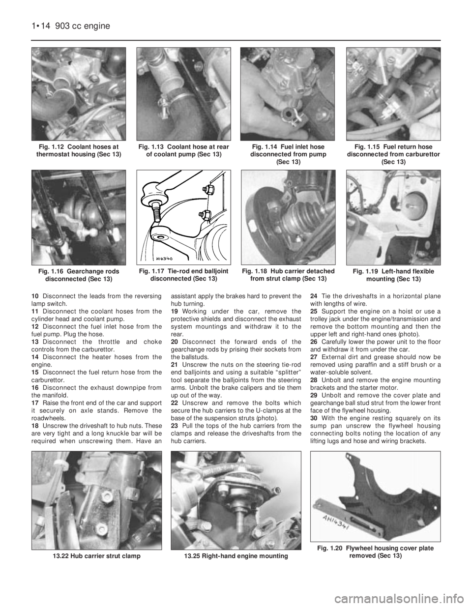
Fig. 1.20 Flywheel housing cover plate
removed (Sec 13)
Fig. 1.19 Left-hand flexible
mounting (Sec 13)
10Disconnect the leads from the reversing
lamp switch.
11Disconnect the coolant hoses from the
cylinder head and coolant pump.
12Disconnect the fuel inlet hose from the
fuel pump. Plug the hose.
13Disconnect the throttle and choke
controls from the carburettor.
14Disconnect the heater hoses from the
engine.
15Disconnect the fuel return hose from the
carburettor.
16Disconnect the exhaust downpipe from
the manifold.
17Raise the front end of the car and support
it securely on axle stands. Remove the
roadwheels.
18Unscrew the driveshaft to hub nuts. These
are very tight and a long knuckle bar will be
required when unscrewing them. Have anassistant apply the brakes hard to prevent the
hub turning.
19Working under the car, remove the
protective shields and disconnect the exhaust
system mountings and withdraw it to the
rear.
20Disconnect the forward ends of the
gearchange rods by prising their sockets from
the ballstuds.
21Unscrew the nuts on the steering tie-rod
end balljoints and using a suitable “splitter”
tool separate the balljoints from the steering
arms. Unbolt the brake calipers and tie them
up out of the way.
22Unscrew and remove the bolts which
secure the hub carriers to the U-clamps at the
base of the suspension struts (photo).
23Pull the tops of the hub carriers from the
clamps and release the driveshafts from the
hub carriers.24Tie the driveshafts in a horizontal plane
with lengths of wire.
25Support the engine on a hoist or use a
trolley jack under the engine/transmission and
remove the bottom mounting and then the
upper left and right-hand ones (photo).
26Carefully lower the power unit to the floor
and withdraw it from under the car.
27External dirt and grease should now be
removed using paraffin and a stiff brush or a
water-soluble solvent.
28Unbolt and remove the engine mounting
brackets and the starter motor.
29Unbolt and remove the cover plate and
gearchange ball stud strut from the lower front
face of the flywheel housing.
30With the engine resting squarely on its
sump pan unscrew the flywheel housing
connecting bolts noting the location of any
lifting lugs and hose and wiring brackets.
1•14 903 cc engine
13.25 Right-hand engine mounting
Fig. 1.18 Hub carrier detached
from strut clamp (Sec 13)
13.22 Hub carrier strut clamp
Fig. 1.17 Tie-rod end balljoint
disconnected (Sec 13)Fig. 1.16 Gearchange rods
disconnected (Sec 13)
Fig. 1.15 Fuel return hose
disconnected from carburettor
(Sec 13)Fig. 1.14 Fuel inlet hose
disconnected from pump
(Sec 13)Fig. 1.13 Coolant hose at rear
of coolant pump (Sec 13)Fig. 1.12 Coolant hoses at
thermostat housing (Sec 13)
Page 49 of 303

Fault finding - all engines
Note: When investigating starting and uneven running faults, do not be tempted into snap diagnosis. Start from the beginning of the check
procedure and follow it through. It will take less time in the long run. Poor performance from an engine in terms of power and economy is not
normally diagnosed quickly. In any event, the ignition and fuel systems must be checked first before assuming any further investigation needs to
be made.
All engines 1•35
1
Engine fails to turn when starter operated
m mBattery discharged
m mBattery terminals loose or corroded
m mBattery earth to body defective
m mEngine/transmission earth strap broken or loose
m mDisconnected or broken wire in starter circuit
m mIgnition/starter switch defective
m mStarter motor or solenoid defective (see Chapter 9)
m mMajor mechanical failure (seizure) or long disuse (piston rings rusted
to bores)
Engine turns and fails to start
m mBattery discharged
m mBattery terminals loose or corroded
m mBattery or engine earth strap loose
m mStarter motor connections loose
m mOil in engine/transmission too thick
m mStarter motor defective
m mVapour lock in fuel line (in hot conditions or at high altitude)
m mBlocked float chamber needle valve
m mFuel pump filter blocked
m mChoked or blocked carburettor jets
m mFaulty fuel pump
m mFuel tank empty
m mOther fuel system fault (see Chapter 3)
m mShorted or disconnected low tension leads
m mDirty, incorrectly set, or pitted contact breaker points
m mContact breaker point spring earthed or broken
m mFaulty condenser
m mDefective ignition switch
m mFaulty coil
m mDamp or dirty HT leads, distributor cap or plug bodies
m mBroken, loose or disconnected LT leads
m mIgnition leads connected wrong way round
m mOther ignition fault (see Chapter 4)
m mValve timing incorrect (after rebuild)
Engine fires but will not run
m
mInsufficient choke (cold engine)
m mFuel starvation or tank empty
m mIgnition fault (see Chapter 4)
m mOther fuel system fault (see Chapter 3)
Engine stalls and will not restart
m
mToo much choke allowing too rich a mixture to wet plugs
m mFloat damaged or leaking or needle not seating
m mFloat lever incorrectly adjusted
m mIgnition failure - sudden
m mIgnition failure - misfiring precedes total stoppage
m mIgnition failure - in severe rain or after traversing water splash
m mNo petrol in petrol tank
m mPetrol tank breather choked
m mSudden obstruction in carburettor
m mWater in fuel system
Engine slow to warm up
m
mChoke linkage maladjusted
m mAir cleaner temperature control unit defective
m mThermostat stuck open (see Chapter 2)
m mOther fuel system fault (see Chapter 3)
Difficult starting when cold
m
mInsufficient choke
m mFouled or incorrectly gapped spark plugs
m mDamp or dirty HT leads, distributor cap or spark plug bodies
m mDirty or maladjusted contact breaker points
m mOther ignition fault or timing maladjustment (see Chapter 4)
m mFuel system or emission control fault (see Chapter 3)
m mPoor compression (may be due to incorrect valve clearances, burnt
or sticking valves, blown head gasket, worn or damaged pistons,
rings or bores)
m mIncorrect valve timing (after rebuild)
Difficult starting when hot
m
mIncorrect use of manual choke
m mFuel line vapour lock (especially in hot weather or at high altitudes)
m mIncorrect ignition timing
m mOther fuel system or emission control fault (see Chapter 3)
m mPoor compression (see above)
Engine lacks power
m
mIgnition timing incorrect
m mContact breaker points incorrectly gapped
m mIncorrectly set spark plugs
m mDirty contact breaker points
m mDistributor automatic advance and retard mechanisms not
functioning correctly
m mOther ignition system fault (see Chapter 4)
m mAir cleaner choked
m mCarburation too rich or too weak
m mFuel filter blocked
m mAir filter blocked
m mFaulty fuel pump giving top and fuel starvation
m mOther fuel system fault (see Chapter 3)
m mPoor compression
m mValve clearances incorrect
m mCarbon build-up in cylinder head
m mSticking or leaking valves
m mWeak or broken valve springs
m mWorn valve guides or stems
m mWorn pistons and piston rings
m mBurnt out valves
m mBlown cylinder head gasket (accompanied by increase in noise)
m mWorn pistons and piston rings
m mWorn or scored cylinder bore
m mBrakes binding
Engine misfires throughout speed range
m
mDefective or fouled spark plug
m mLoose, cracked or defective HT lead
m mMaladjusted, sticking or burnt valves
m mIgnition timing incorrect
m mBlown head gasket
m mFuel contaminated
m mOther ignition fault (see Chapter 4)
m mOther fuel system fault (see Chapter 3)
Poor engine braking
m
mHigh idle speed
m mOther fuel system fault (see Chapter 3)
m mLow compression
Page 58 of 303
Fault finding - cooling and heating systems
2•8 Cooling and heating systems
Overheating
m mInsufficient coolant in system
m mPump ineffective due to slack drivebelt
m mRadiator blocked either internally or externally
m mKinked or collapsed hose causing coolant flow restriction
m mThermostat not working properly
m mEngine out of tune
m mIgnition timing retarded or auto advance malfunction
m mCylinder head gasket blown
m mEngine not yet run-in
m mExhaust system partially blocked
m mEngine oil level too low
m mBrakes binding
Engine running too cool
m
mFaulty, incorrect or missing thermostat
Loss of coolant
m
mLoose hose clips
m mHoses perished or leaking
m mRadiator leaking
m mFiller/pressure cap defective
m mBlown cylinder head gasket
m mCracked cylinder block or head
Heater gives insufficient output
m
mEngine overcooled (see above)
m mHeater matrix blocked
m mHeater controls maladjusted or broken
m mHeater control valve jammed or otherwise
defective
Page 81 of 303
8
System type . . . . . . . . . . . . . . . . . . . . . . . . . . . . . . . . . . . . . . . . . . . Dual-circuit hydraulic with servo unit and pressure regulating valve.
Discs front, drums rear. Handbrake mechanical to rear wheels.
Disc brakes
Type . . . . . . . . . . . . . . . . . . . . . . . . . . . . . . . . . . . . . . . . . . . . . . . . . . . . Single cylinder, sliding caliper
Disc diameter . . . . . . . . . . . . . . . . . . . . . . . . . . . . . . . . . . . . . . . . . . . . . 227.0 mm (8.94 in)
Disc thickness . . . . . . . . . . . . . . . . . . . . . . . . . . . . . . . . . . . . . . . . . . . . . 10.7 to 10.9 mm (0.42 to 0.43 in)
Minimum regrind thickness . . . . . . . . . . . . . . . . . . . . . . . . . . . . . . . . . . 9.0 mm (0.35 in)
Minimum wear thickness of pad friction material . . . . . . . . . . . . . . . . . . 1.5 mm (0.06 in)
Caliper cylinder diameter . . . . . . . . . . . . . . . . . . . . . . . . . . . . . . . . . . . . 48.0 mm (1.89 in)
Drum brakes
Type . . . . . . . . . . . . . . . . . . . . . . . . . . . . . . . . . . . . . . . . . . . . . . . . . . . . Single cylinder, with automatic adjusters
Drum internal diameter . . . . . . . . . . . . . . . . . . . . . . . . . . . . . . . . . . . . . . 185.24 to 185.53 mm (7.30 to 7.31 in)
Maximum regrind diameter . . . . . . . . . . . . . . . . . . . . . . . . . . . . . . . . . . . 187.0 mm (7.37 in)
Minimum shoe lining friction material thickness . . . . . . . . . . . . . . . . . . . 1.5 mm (0.06 in)
Cylinder diameter . . . . . . . . . . . . . . . . . . . . . . . . . . . . . . . . . . . . . . . . . . 19.05 mm (0.75 in)
Master cylinder bore diameter . . . . . . . . . . . . . . . . . . . . . . . . 19.05 mm (0.75 in)
Vacuum servo diameter . . . . . . . . . . . . . . . . . . . . . . . . . . . . . . . 158.5 mm (6.0 in)
Hydraulic fluid type/specification . . . . . . . . . . . . . . . . . . . . . Hydraulic fluid to DOT 3 or 4, or SAE J1703C
System capacity . . . . . . . . . . . . . . . . . . . . . . . . . . . . . . . . . . . . . . . 0.33 litre (0.58 pint)
Torque wrench settingsNm lbf ft
Caliper mounting bracket bolts . . . . . . . . . . . . . . . . . . . . . . . . . . . . . . . 53 39
Rear wheel cylinder mounting bolts . . . . . . . . . . . . . . . . . . . . . . . . . . . . 10 7
Pressure regulating valve mounting bolts . . . . . . . . . . . . . . . . . . . . . . . 20 15
Master cylinder mounting nuts . . . . . . . . . . . . . . . . . . . . . . . . . . . . . . . . 25 18
Rear brake backplate bolts . . . . . . . . . . . . . . . . . . . . . . . . . . . . . . . . . . . 20 15
Chapter 8 Braking system
For modifications, and information applicable to later models, see Supplement at end of manual
Brake disc - inspection, renovation or renewal . . . . . . . . . . . . . . . . . 6
Brake drum - inspection, renovation or renewal . . . . . . . . . . . . . . . . 8
Brake pedal - removal and refitting . . . . . . . . . . . . . . . . . . . . . . . . . . 18
Caliper - removal, overhaul and refitting . . . . . . . . . . . . . . . . . . . . . . 5
Disc pads - inspection and renewal . . . . . . . . . . . . . . . . . . . . . . . . . 3
Fault finding - braking system . . . . . . . . . . . . . . . . See end of Chapter
General description . . . . . . . . . . . . . . . . . . . . . . . . . . . . . . . . . . . . . . 1
Handbrake - adjustment . . . . . . . . . . . . . . . . . . . . . . . . . . . . . . . . . . 16
Handbrake cable - renewal . . . . . . . . . . . . . . . . . . . . . . . . . . . . . . . . 17
Hydraulic hoses and pipes - inspection and renewal . . . . . . . . . . . . 11Hydraulic system - bleeding . . . . . . . . . . . . . . . . . . . . . . . . . . . . . . . 12
Maintenance . . . . . . . . . . . . . . . . . . . . . . . . . . . . . . . . . . . . . . . . . . . 2
Master cylinder - removal, overhaul and refitting . . . . . . . . . . . . . . . 9
Pressure regulating valve . . . . . . . . . . . . . . . . . . . . . . . . . . . . . . . . . 10
Rear brake shoes - inspection and removal . . . . . . . . . . . . . . . . . . . 4
Rear wheel cylinder - removal, overhaul and refitting . . . . . . . . . . . . 7
Stop lamp switch . . . . . . . . . . . . . . . . . . . . . . . . . . . . . . . . . . . . . . . 19
Vacuum servo unit - description . . . . . . . . . . . . . . . . . . . . . . . . . . . . 13
Vacuum servo unit - removal and refitting . . . . . . . . . . . . . . . . . . . . 15
Vacuum servo unit - servicing and testing . . . . . . . . . . . . . . . . . . . . 14
8•1
Specifications Contents
Easy,suitable for
novice with little
experienceFairly easy,suitable
for beginner with
some experienceFairly difficult,
suitable for competent
DIY mechanic
Difficult,suitable for
experienced DIY
mechanicVery difficult,
suitable for expert DIY
or professional
Degrees of difficulty
54321
Page 82 of 303

3.4 Removing the caliper unit
1 General description
The braking system is of four wheel
hydraulic type with discs on the front wheels
and drums on the rear.The hydraulic system is of dual-circuit type
and incorporates a pressure regulator valve to
limit pressure to the rear brakes during heavy
braking to prevent rear wheel lock up.
A vacuum servo unit is fitted to some
models.
The handbrake is mechanically operated on
the rear wheels.
2 Maintenance
1
1At the weekly service check, inspect the
fluid level in the master cylinder reservoir.
Topping up should only be required at very
infrequent intervals and should only be
necessary owing to the need for extra fluid in
the hydraulic system caused by wear of the
friction material of the disc pads and shoe
linings.
2The need for frequent or regular topping up
will be due to a leak in the system, probably
from a hydraulic cylinder seal or a flexible
hose. Correct the problem immediately.
3Use only clean new fluid for topping up. lt
must be of the specified type and have been
stored in a closed container and not have
been shaken for at least 24 hours (photo).
4At regular intervals, check the hoses and
pipelines for condition. Adjust the handbrake
if the lever travel becomes excessive. Check
the condition and security of the brake servo
vacuum hose. All these operations are
described later in this Chapter.
3 Disc pads-
inspection and renewal
2
1Jack up the front of the car and remove the
roadwheels.
2Extract the spring clips and slide out the
locking blocks (photos).
3On SX versions, carefully disconnect the
wear sensor lead connecting plug.
4Lift the caliper body from the disc and
inspect the thickness of the friction material
on each pad (photo). If it is 1.5 mm (0.06 in) or
less, renew the pads.
5Withdraw the pads and the anti-rattle
springs.
6Brush away any dust and dirt from the
caliper, taking care not to inhale the dust - this
contains asbestos and is thus potentially
injurious to health.
7As the new pads are thicker than the old
ones, the caliper piston must be depressed
8•2 Braking system
3.8A Disc pad and anti-rattle spring
Fig. 8.1 Components of the braking system (LHD shown) (Sec 1)
1 Caliper
2 Hose
3 Master cylinder
4 Fluid reservoir5 Cap and fluid level sensor
6 Vacuum servo unit
7 Rear wheel cylinder8 Pipeline
9 Hose
10 Pressure regulating valve
3.2B Removing a locking block
3.2A Removing a disc pad locking block
clip2.3 Fluid reservoir cap and float for
warning switch
Page 83 of 303
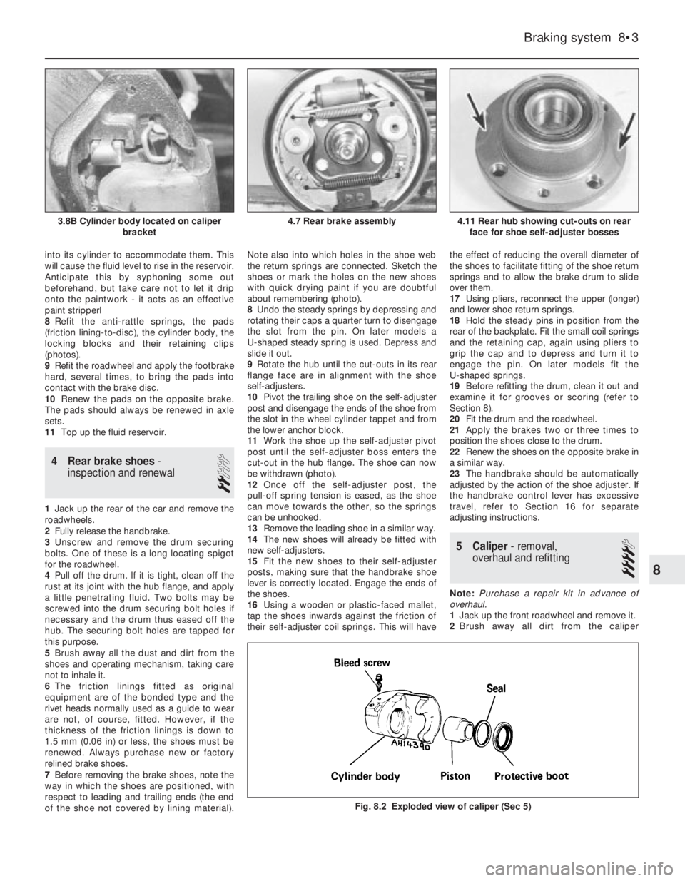
into its cylinder to accommodate them. This
will cause the fluid level to rise in the reservoir.
Anticipate this by syphoning some out
beforehand, but take care not to let it drip
onto the paintwork - it acts as an effective
paint stripperl
8Refit the anti-rattle springs, the pads
(friction lining-to-disc), the cylinder body, the
locking blocks and their retaining clips
(photos).
9Refit the roadwheel and apply the footbrake
hard, several times, to bring the pads into
contact with the brake disc.
10Renew the pads on the opposite brake.
The pads should always be renewed in axle
sets.
11Top up the fluid reservoir.
4 Rear brake shoes-
inspection and renewal
2
1Jack up the rear of the car and remove the
roadwheels.
2Fully release the handbrake.
3Unscrew and remove the drum securing
bolts. One of these is a long locating spigot
for the roadwheel.
4Pull off the drum. lf it is tight, clean off the
rust at its joint with the hub flange, and apply
a little penetrating fluid. Two bolts may be
screwed into the drum securing bolt holes if
necessary and the drum thus eased off the
hub. The securing bolt holes are tapped for
this purpose.
5Brush away all the dust and dirt from the
shoes and operating mechanism, taking care
not to inhale it.
6The friction linings fitted as original
equipment are of the bonded type and the
rivet heads normally used as a guide to wear
are not, of course, fitted. However, if the
thickness of the friction linings is down to
1.5 mm (0.06 in) or less, the shoes must be
renewed. Always purchase new or factory
relined brake shoes.
7Before removing the brake shoes, note the
way in which the shoes are positioned, with
respect to leading and trailing ends (the end
of the shoe not covered by lining material).Note also into which holes in the shoe web
the return springs are connected. Sketch the
shoes or mark the holes on the new shoes
with quick drying paint if you are doubtful
about remembering (photo).
8Undo the steady springs by depressing and
rotating their caps a quarter turn to disengage
the slot from the pin. On later models a
U-shaped steady spring is used. Depress and
slide it out.
9Rotate the hub until the cut-outs in its rear
flange face are in alignment with the shoe
self-adjusters.
10Pivot the trailing shoe on the self-adjuster
post and disengage the ends of the shoe from
the slot in the wheel cylinder tappet and from
the lower anchor block.
11Work the shoe up the self-adjuster pivot
post until the self-adjuster boss enters the
cut-out in the hub flange. The shoe can now
be withdrawn (photo).
12Once off the self-adjuster post, the
pull-off spring tension is eased, as the shoe
can move towards the other, so the springs
can be unhooked.
13Remove the leading shoe in a similar way.
14The new shoes will already be fitted with
new self-adjusters.
15Fit the new shoes to their self-adjuster
posts, making sure that the handbrake shoe
lever is correctly located. Engage the ends of
the shoes.
16Using a wooden or plastic-faced mallet,
tap the shoes inwards against the friction of
their self-adjuster coil springs. This will havethe effect of reducing the overall diameter of
the shoes to facilitate fitting of the shoe return
springs and to allow the brake drum to slide
over them.
17Using pliers, reconnect the upper (longer)
and lower shoe return springs.
18Hold the steady pins in position from the
rear of the backplate. Fit the small coil springs
and the retaining cap, again using pliers to
grip the cap and to depress and turn it to
engage the pin. On later models fit the
U-shaped springs.
19Before refitting the drum, clean it out and
examine it for grooves or scoring (refer to
Section 8).
20Fit the drum and the roadwheel.
21Apply the brakes two or three times to
position the shoes close to the drum.
22Renew the shoes on the opposite brake in
a similar way.
23The handbrake should be automatically
adjusted by the action of the shoe adjuster. If
the handbrake control lever has excessive
travel, refer to Section 16 for separate
adjusting instructions.
5 Caliper- removal,
overhaul and refitting
4
Note: Purchase a repair kit in advance of
overhaul.
1Jack up the front roadwheel and remove it.
2Brush away all dirt from the caliper
Braking system 8•3
4.11 Rear hub showing cut-outs on rear
face for shoe self-adjuster bosses4.7 Rear brake assembly3.8B Cylinder body located on caliper
bracket
Fig. 8.2 Exploded view of caliper (Sec 5)
8
Page 85 of 303
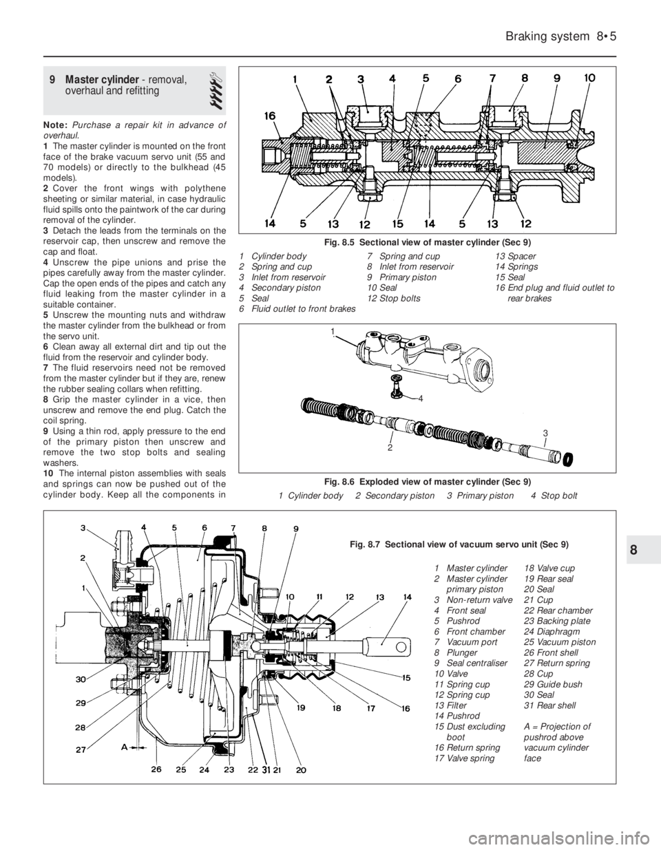
9 Master cylinder- removal,
overhaul and refitting
4
Note: Purchase a repair kit in advance of
overhaul.
1The master cylinder is mounted on the front
face of the brake vacuum servo unit (55 and
70 models) or directly to the bulkhead (45
models).
2Cover the front wings with polythene
sheeting or similar material, in case hydraulic
fluid spills onto the paintwork of the car during
removal of the cylinder.
3Detach the leads from the terminals on the
reservoir cap, then unscrew and remove the
cap and float.
4Unscrew the pipe unions and prise the
pipes carefully away from the master cylinder.
Cap the open ends of the pipes and catch any
fluid leaking from the master cylinder in a
suitable container.
5Unscrew the mounting nuts and withdraw
the master cylinder from the bulkhead or from
the servo unit.
6Clean away all external dirt and tip out the
fluid from the reservoir and cylinder body.
7The fluid reservoirs need not be removed
from the master cylinder but if they are, renew
the rubber sealing collars when refitting.
8Grip the master cylinder in a vice, then
unscrew and remove the end plug. Catch the
coil spring.
9Using a thin rod, apply pressure to the end
of the primary piston then unscrew and
remove the two stop bolts and sealing
washers.
10The internal piston assemblies with seals
and springs can now be pushed out of the
cylinder body. Keep all the components in
Braking system 8•5
Fig. 8.5 Sectional view of master cylinder (Sec 9)
1 Cylinder body
2 Spring and cup
3 Inlet from reservoir
4 Secondary piston
5 Seal
6 Fluid outlet to front brakes7 Spring and cup
8 Inlet from reservoir
9 Primary piston
10 Seal
12 Stop bolts13 Spacer
14 Springs
15 Seal
16 End plug and fluid outlet to
rear brakes
Fig. 8.6 Exploded view of master cylinder (Sec 9)
1 Cylinder body 2 Secondary piston 3 Primary piston 4 Stop bolt
8Fig. 8.7 Sectional view of vacuum servo unit (Sec 9)
1 Master cylinder
2 Master cylinder
primary piston
3 Non-return valve
4 Front seal
5 Pushrod
6 Front chamber
7 Vacuum port
8 Plunger
9 Seal centraliser
10 Valve
11 Spring cup
12 Spring cup
13 Filter
14 Pushrod
15 Dust excluding
boot
16 Return spring
17 Valve spring18 Valve cup
19 Rear seal
20 Seal
21 Cup
22 Rear chamber
23 Backing plate
24 Diaphragm
25 Vacuum piston
26 Front shell
27 Return spring
28 Cup
29 Guide bush
30 Seal
31 Rear shell
A = Projection of
pushrod above
vacuum cylinder
face
2
3
1
4