1983 FIAT UNO brake fluid
[x] Cancel search: brake fluidPage 5 of 303

Safety First!0•5
Working on your car can be dangerous.
This page shows just some of the potential
risks and hazards, with the aim of creating a
safety-conscious attitude.
General hazards
Scalding
• Don’t remove the radiator or expansion
tank cap while the engine is hot.
• Engine oil, automatic transmission fluid or
power steering fluid may also be dangerously
hot if the engine has recently been running.
Burning
• Beware of burns from the exhaust system
and from any part of the engine. Brake discs
and drums can also be extremely hot
immediately after use.
Crushing
• When working under or near
a raised vehicle,
always
supplement the
jack with axle
stands, or use
drive-on
ramps.
Never
venture
under a car which
is only supported by a jack.
• Take care if loosening or tightening high-
torque nuts when the vehicle is on stands.
Initial loosening and final tightening should
be done with the wheels on the ground.
Fire
• Fuel is highly flammable; fuel vapour is
explosive.
• Don’t let fuel spill onto a hot engine.
• Do not smoke or allow naked lights
(including pilot lights) anywhere near a
vehicle being worked on. Also beware of
creating sparks
(electrically or by use of tools).
• Fuel vapour is heavier than air, so don’t
work on the fuel system with the vehicle over
an inspection pit.
• Another cause of fire is an electrical
overload or short-circuit. Take care when
repairing or modifying the vehicle wiring.
• Keep a fire extinguisher handy, of a type
suitable for use on fuel and electrical fires.
Electric shock
• Ignition HT
voltage can be
dangerous,
especially to
people with heart
problems or a
pacemaker. Don’t
work on or near the
ignition system with
the engine running or
the ignition switched on.• Mains voltage is also dangerous. Make
sure that any mains-operated equipment is
correctly earthed. Mains power points should
be protected by a residual current device
(RCD) circuit breaker.
Fume or gas intoxication
• Exhaust fumes are
poisonous; they often
contain carbon
monoxide, which is
rapidly fatal if inhaled.
Never run the
engine in a
confined space
such as a garage
with the doors shut.
• Fuel vapour is also
poisonous, as are the vapours from some
cleaning solvents and paint thinners.
Poisonous or irritant substances
• Avoid skin contact with battery acid and
with any fuel, fluid or lubricant, especially
antifreeze, brake hydraulic fluid and Diesel
fuel. Don’t syphon them by mouth. If such a
substance is swallowed or gets into the eyes,
seek medical advice.
• Prolonged contact with used engine oil can
cause skin cancer. Wear gloves or use a
barrier cream if necessary. Change out of oil-
soaked clothes and do not keep oily rags in
your pocket.
• Air conditioning refrigerant forms a
poisonous gas if exposed to a naked flame
(including a cigarette). It can also cause skin
burns on contact.
Asbestos
• Asbestos dust can cause cancer if inhaled
or swallowed. Asbestos may be found in
gaskets and in brake and clutch linings.
When dealing with such components it is
safest to assume that they contain asbestos.
Special hazards
Hydrofluoric acid
• This extremely corrosive acid is formed
when certain types of synthetic rubber, found
in some O-rings, oil seals, fuel hoses etc, are
exposed to temperatures above 400
0C. The
rubber changes into a charred or sticky
substance containing the acid. Once formed,
the acid remains dangerous for years. If it
gets onto the skin, it may be necessary to
amputate the limb concerned.
• When dealing with a vehicle which has
suffered a fire, or with components salvaged
from such a vehicle, wear protective gloves
and discard them after use.
The battery
• Batteries contain sulphuric acid, which
attacks clothing, eyes and skin. Take care
when topping-up or carrying the battery.
• The hydrogen gas given off by the battery
is highly explosive. Never cause a spark or
allow a naked light nearby. Be careful when
connecting and disconnecting battery
chargers or jump leads.
Air bags
• Air bags can cause injury if they go off
accidentally. Take care when removing the
steering wheel and/or facia. Special storage
instructions may apply.
Diesel injection equipment
• Diesel injection pumps supply fuel at very
high pressure. Take care when working on
the fuel injectors and fuel pipes.
Warning: Never expose the hands,
face or any other part of the body
to injector spray; the fuel can
penetrate the skin with potentially fatal
results.
Remember...
DO
• Do use eye protection when using power
tools, and when working under the vehicle.
• Do wear gloves or use barrier cream to
protect your hands when necessary.
• Do get someone to check periodically
that all is well when working alone on the
vehicle.
• Do keep loose clothing and long hair well
out of the way of moving mechanical parts.
• Do remove rings, wristwatch etc, before
working on the vehicle – especially the
electrical system.
• Do ensure that any lifting or jacking
equipment has a safe working load rating
adequate for the job.
A few tips
DON’T
• Don’t attempt to lift a heavy component
which may be beyond your capability – get
assistance.
• Don’t rush to finish a job, or take
unverified short cuts.
• Don’t use ill-fitting tools which may slip
and cause injury.
• Don’t leave tools or parts lying around
where someone can trip over them. Mop
up oil and fuel spills at once.
• Don’t allow children or pets to play in or
near a vehicle being worked on.
Page 9 of 303
Roadside Repairs0•9
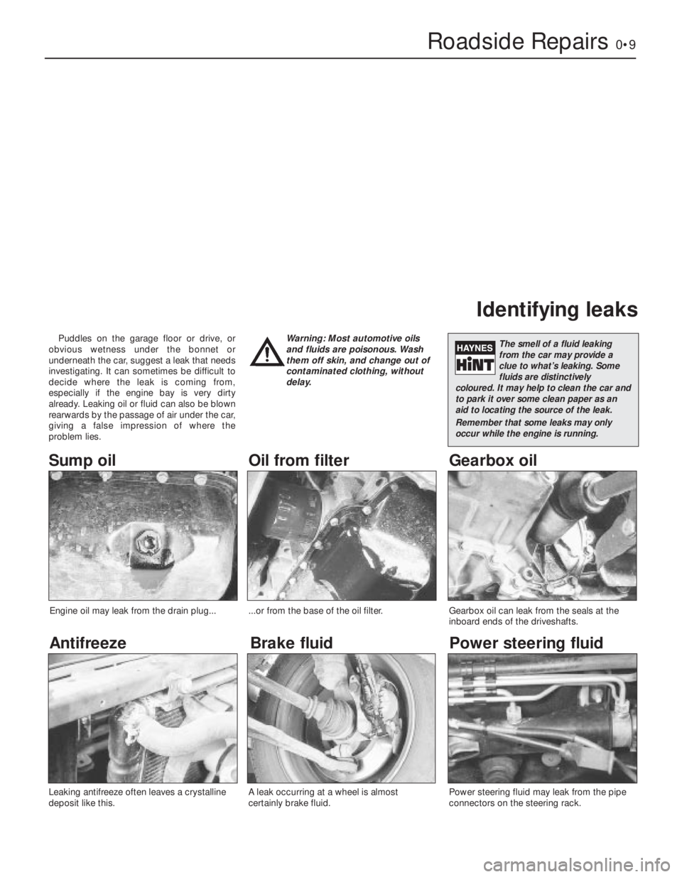
Puddles on the garage floor or drive, or
obvious wetness under the bonnet or
underneath the car, suggest a leak that needs
investigating. It can sometimes be difficult to
decide where the leak is coming from,
especially if the engine bay is very dirty
already. Leaking oil or fluid can also be blown
rearwards by the passage of air under the car,
giving a false impression of where the
problem lies.Warning: Most automotive oils
and fluids are poisonous. Wash
them off skin, and change out of
contaminated clothing, without
delay.
Identifying leaks
The smell of a fluid leaking
from the car may provide a
clue to what’s leaking. Some
fluids are distinctively
coloured. It may help to clean the car and
to park it over some clean paper as an
aid to locating the source of the leak.
Remember that some leaks may only
occur while the engine is running.
Sump oil Gearbox oil
Brake fluid
Power steering fluid
Oil from filter
Antifreeze
Engine oil may leak from the drain plug......or from the base of the oil filter.
Leaking antifreeze often leaves a crystalline
deposit like this.Gearbox oil can leak from the seals at the
inboard ends of the driveshafts.
A leak occurring at a wheel is almost
certainly brake fluid.Power steering fluid may leak from the pipe
connectors on the steering rack.
Page 10 of 303

0•10Routine maintenance
Maintenance is essential for ensuring safety and desirable for the
purpose of getting the best in terms of performance and economy
from the car. Over the years the need for periodic lubrication has been
greatly reduced if not totally eliminated. This has unfortunately tended
to lead some owners to think that because no such action is required
the items either no longer exist or will last forever. This is certainly not
the case; it is essential to carry out regular visual examinations as
comprehensively as possible in order to spot any possible defects at
an early stage before they develop into major and expensive repairs.
For information applicable to later models, see Supplement.
Every 250 miles (400 km), weekly,
or before a long journey
m mCheck engine oil level
m mCheck brake reservoir fluid level
m mCheck tyre pressures
m mCheck operation of all lights and horn
m mTop up washer fluid reservoirs, adding a screen
wash, and check operation of washers and wipers
m mCheck coolant level
m mCheck battery electrolyte level
Every 6000 miles (10 000 km)
or six months, whichever comes first
m mRenew engine oil and filter (Chapter 1, Section 2)
m mCheck drivebelt tension (Chapter 2, Section 8)
m mCheck carburettor idle speed and mixture
adjustments (Chapter 3)
m mCheck contact points and dwell angle (mechanical
breaker distributors) (Chapter 4, Section 3)
m mCheck tyre tread wear (Chapter 7, Section 7)
m mCheck disc pads for wear (Chapter 8, Section 3)
Every 36 000 miles (60 000 km)
or three years, whichever comes first
m mRenew the timing belt - 1116 and 1299/1301 cc
(Chapter 1, Section 28)
m mCheck exhaust system for corrosion (Chapter 3,
Section 19)
m mRenew contact breaker points and adjust dwell
angle (mechanical breaker distributors) (Chapter 4,
Section 3)
m mCheck and adjust ignition timing (Chapter 4,
Section 4)
m mRenew spark plugs (Chapter 4, Section 11)
m mCheck clutch adjustment (Chapter 5, Section 2)
m mCheck transmission oil level (Chapter 6, Section 2)
m mCheck driveshaft and steering rack gaiters for splits
(Chapters 7 and 10)
m mCheck rear brake shoe linings for wear (Chapter 8,
Section 4)
m mCheck handbrake travel (Chapter 8, Section 16)
m mCheck headlamp beam alignment (Chapter 9,
Section 17)
m mCheck balljoints for wear (Chapter 10, Section 2)
m mCheck front wheel alignment (Chapter 10, Section 8)
m mCheck suspension bushes for wear (Chapter 11,
Section 2)
m mCheck seat belts for fraying (Chapter 12, Section 23)
m mLubricate controls, hinges and locks
Every 24 000 miles (40 000 km)
or two years, whichever comes first
m mRenew coolant anti-freeze mixture (Chapter 2,
Section 3)
m mRenew transmission oil (Chapter 6, Section 2)
m mRenew brake hydraulic fluid (Chapter 8, Section 12)
m mCheck for underbody corrosion and clean out door
and sill drain holes (Chapter 12, Section 2)
Every 12 000 miles (20 000 km) or
12 months, whichever comes first
m mCheck and adjust valve clearances (Chapter 1,
Sections 5 and 26)
m mRenew air cleaner element (Chapter 3, Section 2)
Page 11 of 303
Routine maintenance0•11
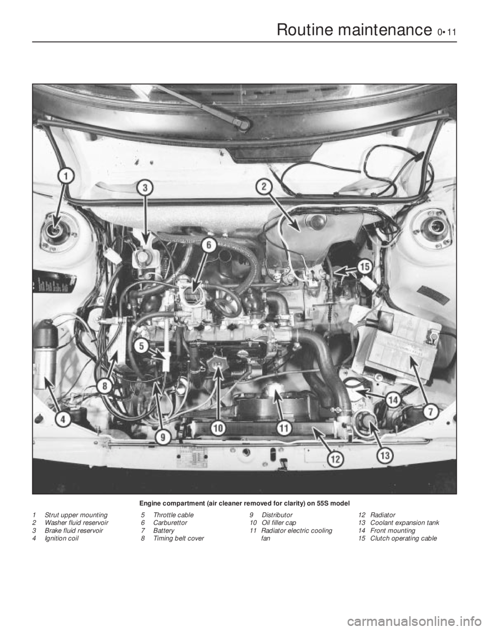
Engine compartment (air cleaner removed for clarity) on 55S model
1 Strut upper mounting
2 Washer fluid reservoir
3 Brake fluid reservoir
4 Ignition coil5 Throttle cable
6 Carburettor
7 Battery
8 Timing belt cover9 Distributor
10 Oil filler cap
11 Radiator electric cooling
fan12 Radiator
13 Coolant expansion tank
14 Front mounting
15 Clutch operating cable
Page 13 of 303
Lubricants and Fluids0•13
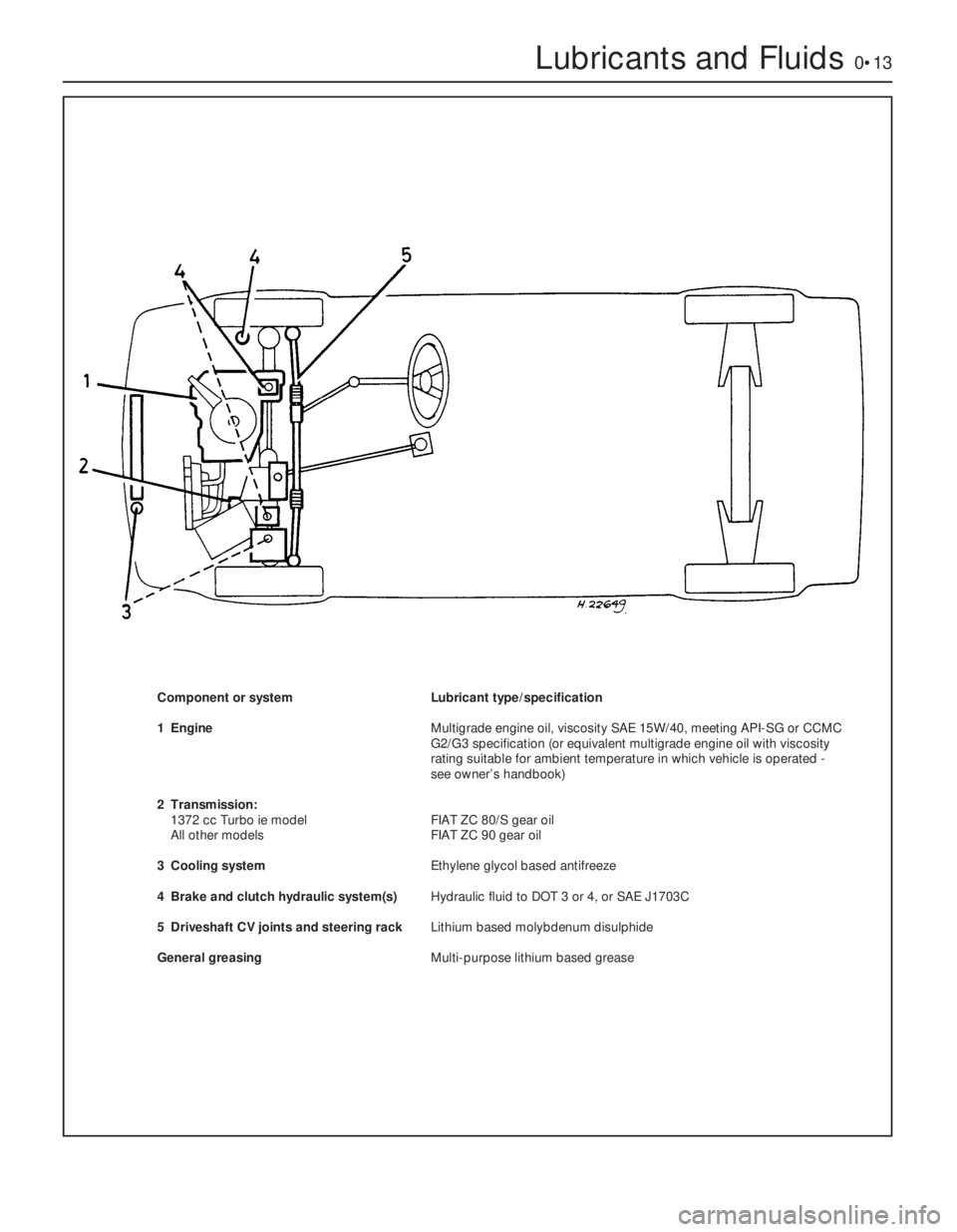
Component or system Lubricant type/specification
1 EngineMultigrade engine oil, viscosity SAE 15W/40, meeting API-SG or CCMC
G2/G3 specification (or equivalent multigrade engine oil with viscosity
rating suitable for ambient temperature in which vehicle is operated -
see owner’s handbook)
2 Transmission:
1372 cc Turbo ie model FIAT ZC 80/S gear oil
All other models FIAT ZC 90 gear oil
3 Cooling systemEthylene glycol based antifreeze
4 Brake and clutch hydraulic system(s)Hydraulic fluid to DOT 3 or 4, or SAE J1703C
5 Driveshaft CV joints and steering rackLithium based molybdenum disulphide
General greasingMulti-purpose lithium based grease
Page 81 of 303
8
System type . . . . . . . . . . . . . . . . . . . . . . . . . . . . . . . . . . . . . . . . . . . Dual-circuit hydraulic with servo unit and pressure regulating valve.
Discs front, drums rear. Handbrake mechanical to rear wheels.
Disc brakes
Type . . . . . . . . . . . . . . . . . . . . . . . . . . . . . . . . . . . . . . . . . . . . . . . . . . . . Single cylinder, sliding caliper
Disc diameter . . . . . . . . . . . . . . . . . . . . . . . . . . . . . . . . . . . . . . . . . . . . . 227.0 mm (8.94 in)
Disc thickness . . . . . . . . . . . . . . . . . . . . . . . . . . . . . . . . . . . . . . . . . . . . . 10.7 to 10.9 mm (0.42 to 0.43 in)
Minimum regrind thickness . . . . . . . . . . . . . . . . . . . . . . . . . . . . . . . . . . 9.0 mm (0.35 in)
Minimum wear thickness of pad friction material . . . . . . . . . . . . . . . . . . 1.5 mm (0.06 in)
Caliper cylinder diameter . . . . . . . . . . . . . . . . . . . . . . . . . . . . . . . . . . . . 48.0 mm (1.89 in)
Drum brakes
Type . . . . . . . . . . . . . . . . . . . . . . . . . . . . . . . . . . . . . . . . . . . . . . . . . . . . Single cylinder, with automatic adjusters
Drum internal diameter . . . . . . . . . . . . . . . . . . . . . . . . . . . . . . . . . . . . . . 185.24 to 185.53 mm (7.30 to 7.31 in)
Maximum regrind diameter . . . . . . . . . . . . . . . . . . . . . . . . . . . . . . . . . . . 187.0 mm (7.37 in)
Minimum shoe lining friction material thickness . . . . . . . . . . . . . . . . . . . 1.5 mm (0.06 in)
Cylinder diameter . . . . . . . . . . . . . . . . . . . . . . . . . . . . . . . . . . . . . . . . . . 19.05 mm (0.75 in)
Master cylinder bore diameter . . . . . . . . . . . . . . . . . . . . . . . . 19.05 mm (0.75 in)
Vacuum servo diameter . . . . . . . . . . . . . . . . . . . . . . . . . . . . . . . 158.5 mm (6.0 in)
Hydraulic fluid type/specification . . . . . . . . . . . . . . . . . . . . . Hydraulic fluid to DOT 3 or 4, or SAE J1703C
System capacity . . . . . . . . . . . . . . . . . . . . . . . . . . . . . . . . . . . . . . . 0.33 litre (0.58 pint)
Torque wrench settingsNm lbf ft
Caliper mounting bracket bolts . . . . . . . . . . . . . . . . . . . . . . . . . . . . . . . 53 39
Rear wheel cylinder mounting bolts . . . . . . . . . . . . . . . . . . . . . . . . . . . . 10 7
Pressure regulating valve mounting bolts . . . . . . . . . . . . . . . . . . . . . . . 20 15
Master cylinder mounting nuts . . . . . . . . . . . . . . . . . . . . . . . . . . . . . . . . 25 18
Rear brake backplate bolts . . . . . . . . . . . . . . . . . . . . . . . . . . . . . . . . . . . 20 15
Chapter 8 Braking system
For modifications, and information applicable to later models, see Supplement at end of manual
Brake disc - inspection, renovation or renewal . . . . . . . . . . . . . . . . . 6
Brake drum - inspection, renovation or renewal . . . . . . . . . . . . . . . . 8
Brake pedal - removal and refitting . . . . . . . . . . . . . . . . . . . . . . . . . . 18
Caliper - removal, overhaul and refitting . . . . . . . . . . . . . . . . . . . . . . 5
Disc pads - inspection and renewal . . . . . . . . . . . . . . . . . . . . . . . . . 3
Fault finding - braking system . . . . . . . . . . . . . . . . See end of Chapter
General description . . . . . . . . . . . . . . . . . . . . . . . . . . . . . . . . . . . . . . 1
Handbrake - adjustment . . . . . . . . . . . . . . . . . . . . . . . . . . . . . . . . . . 16
Handbrake cable - renewal . . . . . . . . . . . . . . . . . . . . . . . . . . . . . . . . 17
Hydraulic hoses and pipes - inspection and renewal . . . . . . . . . . . . 11Hydraulic system - bleeding . . . . . . . . . . . . . . . . . . . . . . . . . . . . . . . 12
Maintenance . . . . . . . . . . . . . . . . . . . . . . . . . . . . . . . . . . . . . . . . . . . 2
Master cylinder - removal, overhaul and refitting . . . . . . . . . . . . . . . 9
Pressure regulating valve . . . . . . . . . . . . . . . . . . . . . . . . . . . . . . . . . 10
Rear brake shoes - inspection and removal . . . . . . . . . . . . . . . . . . . 4
Rear wheel cylinder - removal, overhaul and refitting . . . . . . . . . . . . 7
Stop lamp switch . . . . . . . . . . . . . . . . . . . . . . . . . . . . . . . . . . . . . . . 19
Vacuum servo unit - description . . . . . . . . . . . . . . . . . . . . . . . . . . . . 13
Vacuum servo unit - removal and refitting . . . . . . . . . . . . . . . . . . . . 15
Vacuum servo unit - servicing and testing . . . . . . . . . . . . . . . . . . . . 14
8•1
Specifications Contents
Easy,suitable for
novice with little
experienceFairly easy,suitable
for beginner with
some experienceFairly difficult,
suitable for competent
DIY mechanic
Difficult,suitable for
experienced DIY
mechanicVery difficult,
suitable for expert DIY
or professional
Degrees of difficulty
54321
Page 82 of 303

3.4 Removing the caliper unit
1 General description
The braking system is of four wheel
hydraulic type with discs on the front wheels
and drums on the rear.The hydraulic system is of dual-circuit type
and incorporates a pressure regulator valve to
limit pressure to the rear brakes during heavy
braking to prevent rear wheel lock up.
A vacuum servo unit is fitted to some
models.
The handbrake is mechanically operated on
the rear wheels.
2 Maintenance
1
1At the weekly service check, inspect the
fluid level in the master cylinder reservoir.
Topping up should only be required at very
infrequent intervals and should only be
necessary owing to the need for extra fluid in
the hydraulic system caused by wear of the
friction material of the disc pads and shoe
linings.
2The need for frequent or regular topping up
will be due to a leak in the system, probably
from a hydraulic cylinder seal or a flexible
hose. Correct the problem immediately.
3Use only clean new fluid for topping up. lt
must be of the specified type and have been
stored in a closed container and not have
been shaken for at least 24 hours (photo).
4At regular intervals, check the hoses and
pipelines for condition. Adjust the handbrake
if the lever travel becomes excessive. Check
the condition and security of the brake servo
vacuum hose. All these operations are
described later in this Chapter.
3 Disc pads-
inspection and renewal
2
1Jack up the front of the car and remove the
roadwheels.
2Extract the spring clips and slide out the
locking blocks (photos).
3On SX versions, carefully disconnect the
wear sensor lead connecting plug.
4Lift the caliper body from the disc and
inspect the thickness of the friction material
on each pad (photo). If it is 1.5 mm (0.06 in) or
less, renew the pads.
5Withdraw the pads and the anti-rattle
springs.
6Brush away any dust and dirt from the
caliper, taking care not to inhale the dust - this
contains asbestos and is thus potentially
injurious to health.
7As the new pads are thicker than the old
ones, the caliper piston must be depressed
8•2 Braking system
3.8A Disc pad and anti-rattle spring
Fig. 8.1 Components of the braking system (LHD shown) (Sec 1)
1 Caliper
2 Hose
3 Master cylinder
4 Fluid reservoir5 Cap and fluid level sensor
6 Vacuum servo unit
7 Rear wheel cylinder8 Pipeline
9 Hose
10 Pressure regulating valve
3.2B Removing a locking block
3.2A Removing a disc pad locking block
clip2.3 Fluid reservoir cap and float for
warning switch
Page 83 of 303
into its cylinder to accommodate them. This
will cause the fluid level to rise in the reservoir.
Anticipate this by syphoning some out
beforehand, but take care not to let it drip
onto the paintwork - it acts as an effective
paint stripperl
8Refit the anti-rattle springs, the pads
(friction lining-to-disc), the cylinder body, the
locking blocks and their retaining clips
(photos).
9Refit the roadwheel and apply the footbrake
hard, several times, to bring the pads into
contact with the brake disc.
10Renew the pads on the opposite brake.
The pads should always be renewed in axle
sets.
11Top up the fluid reservoir.
4 Rear brake shoes-
inspection and renewal
2
1Jack up the rear of the car and remove the
roadwheels.
2Fully release the handbrake.
3Unscrew and remove the drum securing
bolts. One of these is a long locating spigot
for the roadwheel.
4Pull off the drum. lf it is tight, clean off the
rust at its joint with the hub flange, and apply
a little penetrating fluid. Two bolts may be
screwed into the drum securing bolt holes if
necessary and the drum thus eased off the
hub. The securing bolt holes are tapped for
this purpose.
5Brush away all the dust and dirt from the
shoes and operating mechanism, taking care
not to inhale it.
6The friction linings fitted as original
equipment are of the bonded type and the
rivet heads normally used as a guide to wear
are not, of course, fitted. However, if the
thickness of the friction linings is down to
1.5 mm (0.06 in) or less, the shoes must be
renewed. Always purchase new or factory
relined brake shoes.
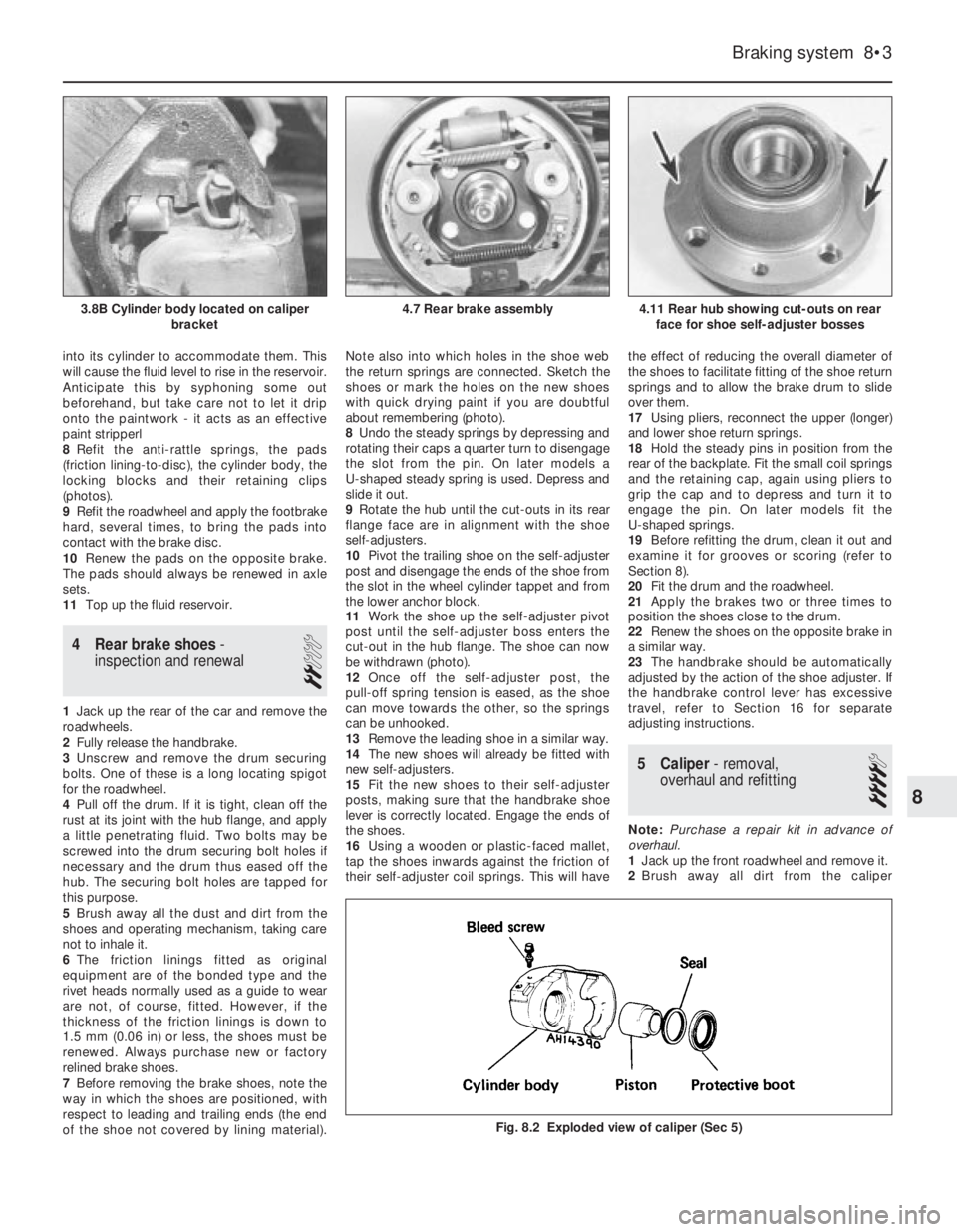
7Before removing the brake shoes, note the
way in which the shoes are positioned, with
respect to leading and trailing ends (the end
of the shoe not covered by lining material).Note also into which holes in the shoe web
the return springs are connected. Sketch the
shoes or mark the holes on the new shoes
with quick drying paint if you are doubtful
about remembering (photo).
8Undo the steady springs by depressing and
rotating their caps a quarter turn to disengage
the slot from the pin. On later models a
U-shaped steady spring is used. Depress and
slide it out.
9Rotate the hub until the cut-outs in its rear
flange face are in alignment with the shoe
self-adjusters.
10Pivot the trailing shoe on the self-adjuster
post and disengage the ends of the shoe from
the slot in the wheel cylinder tappet and from
the lower anchor block.
11Work the shoe up the self-adjuster pivot
post until the self-adjuster boss enters the
cut-out in the hub flange. The shoe can now
be withdrawn (photo).
12Once off the self-adjuster post, the
pull-off spring tension is eased, as the shoe
can move towards the other, so the springs
can be unhooked.
13Remove the leading shoe in a similar way.
14The new shoes will already be fitted with
new self-adjusters.
15Fit the new shoes to their self-adjuster
posts, making sure that the handbrake shoe
lever is correctly located. Engage the ends of
the shoes.
16Using a wooden or plastic-faced mallet,
tap the shoes inwards against the friction of
their self-adjuster coil springs. This will havethe effect of reducing the overall diameter of
the shoes to facilitate fitting of the shoe return
springs and to allow the brake drum to slide
over them.
17Using pliers, reconnect the upper (longer)
and lower shoe return springs.
18Hold the steady pins in position from the
rear of the backplate. Fit the small coil springs
and the retaining cap, again using pliers to
grip the cap and to depress and turn it to
engage the pin. On later models fit the
U-shaped springs.
19Before refitting the drum, clean it out and
examine it for grooves or scoring (refer to
Section 8).
20Fit the drum and the roadwheel.
21Apply the brakes two or three times to
position the shoes close to the drum.
22Renew the shoes on the opposite brake in
a similar way.
23The handbrake should be automatically
adjusted by the action of the shoe adjuster. If
the handbrake control lever has excessive
travel, refer to Section 16 for separate
adjusting instructions.
5 Caliper- removal,
overhaul and refitting
4
Note: Purchase a repair kit in advance of
overhaul.
1Jack up the front roadwheel and remove it.
2Brush away all dirt from the caliper
Braking system 8•3
4.11 Rear hub showing cut-outs on rear
face for shoe self-adjuster bosses4.7 Rear brake assembly3.8B Cylinder body located on caliper
bracket
Fig. 8.2 Exploded view of caliper (Sec 5)
8