1983 FIAT UNO brake fluid
[x] Cancel search: brake fluidPage 84 of 303
assembly and the flexible pipe, particularly the
fixing bracket and union at the car end of the
flexible pipe.
3Have ready a container suitable to catch
the brake fluid, and sheets of clean
newspaper on which to put parts.
4Take out the spring clips and locking
blocks, and take the caliper off the support
bracket.
5Disconnect the hydraulic flexible pipe at the
under wing support bracket and cap both
pipe ends. It may help to prevent loss of fluid
if the vent in the reservoir cap is sealed with
adhesive tape, to create a vacuum.
6Remove the caliper to the bench or other
work surface, and clean it thoroughly with
hydraulic fluid or methylated spirit.
7Depress the piston until the dust excluding
boot can be removed.
8Now apply air pressure to the flexible hose
and eject the piston. Quite a low pressure is
required for this, such as can be generated
with a hand or foot operated pump.
9Pick out the piston seal from its groove in
the cylinder. Use a sharp probe, but take care
to avoid scratching the cylinder bore.
10Examine the surface of the piston and
cylinder bore. If either is corroded, scored or
shows metal-to-metal rubbed areas, the
complete assembly should be renewed.
11If the components are in good condition,
discard the oil seals, clean the piston and
cylinder and fit the new seal for the piston.
This is included in the repair kit. Use the
fingers only to manipulate it into its groove.
12Lubricate the piston with clean hydraulic
fluid and insert it partially into the cylinder.
13Fit the new dust excluding boot to its
projecting end, push the piston fully into the
cylinder and engage the dust excluder with
the rim of the cylinder.
14Refit the caliper, reconnect the flexible
hose, then bleed the front hydraulic circuit
(refer to Section 12).
6 Brake disc- inspection,
renovation or renewal
2
1Whenever the front disc pads are being
checked for wear, take the opportunity to
inspect the discs for deep scoring or
grooving. After a high mileage the disc may
become reduced in thickness away from the
extreme outer edge of the disc. lf this wear is
rapid, it is possible that the friction pads are of
too hard a type.
2If the disc has evidence of many tiny cracks,
these may be caused by overheating due to a
seized caliper piston in the “applied” position.
3The foregoing conditions may be corrected
by regrinding the disc provided that the
thickness of the disc is not reduced below
that specified by such action. Alternatively, fit
a new disc.
4To remove a disc, take off the caliper andpads as described in Sections 3 and 5. Tie the
caliper up, out of the way.
5Knock back the tabs of the lockplates and
unbolt the caliper support bracket from the
hub carrier.
6Unscrew and remove the two bolts which
hold the disc assembly to the hub. One of
these bolts is for wheel locating purposes.
7Pull the disc from the hub.
8Refitting is a reversal of the removal
process. If the disc has excessive run-out,
repositioning it in relation to the hub may
bring it within tolerance by cancelling out the
run-out characteristics in the hub and disc,
once the most suitable fitted position has
been found.
7 Rear wheel cylinder-
removal, overhaul and refitting
4
Note: Purchase a repair kit in advance of
overhaul.
1If fluid seepage is observed from the ends
of the rear wheel cylinder when the brake
drum has been removed, the seals are leaking
and immediate action must be taken.
2Although the cylinder can be dismantled
without taking it from the backplate, this is not
recommended due to the possibility of under
wing dirt and mud dropping onto the
components as work proceeds. 3Remove the brake shoes, as described in
Section 4.
4Disconnect the hydraulic line from the
wheel cylinder and cap the open end of the
pipe. lt may help to reduce the loss of fluid if
the vent hole in the reservoir cap is taped over
to create a vacuum.
5Unscrew and remove the setscrews which
hold the cylinder to the backplate and
withdraw the cylinder. Prise off the rubber
dust excluding boots.
6Apply gentle air pressure from a hand or
foot operated pump to eject the pistons and
spring. Alternatively, tap the end of the
cylinder on a piece of hardwood and the
pistons should move out.
7Inspect the piston and cylinder bore
surfaces for scoring, corrosion or evidence of
metal-to-metal rubbing areas. lf these are
found, discard the assembly and purchase a
new one.
8If the components are in good condition,
note which way round the lips are fitted, then
discard the seals and boots and wash the
pistons and cylinder bore in clean hydraulic
fluid or methylated spirit.
9Manipulate the new seals into position,
using the fingers only for this job.
10Dip the pistons in clean hydraulic fluid and
insert them with the coil spring and washers
into the cylinder.
11Fit the new dust excluding boots.
12Refit the wheel cylinder to the backplate,
reconnect the hydraulic pipe, then refit the
shoes, the drum and the roadwheel.
13Bleed the rear hydraulic circuit as
described in Section 12.
8 Brake drum- inspection,
renovation or renewal
2
1Whenever the rear brake linings are being
checked for wear, take the opportunity to
inspect the internal surfaces of the brake
drums.
2If the drums are grooved or deeply scored,
they may be reground, provided that their new
internal diameter will not then exceed the
specified dimension. If it will, or the drum is
cracked, it must be renewed.
3Removal and refitting of a brake drum is
described in Section 4.
8•4 Braking system
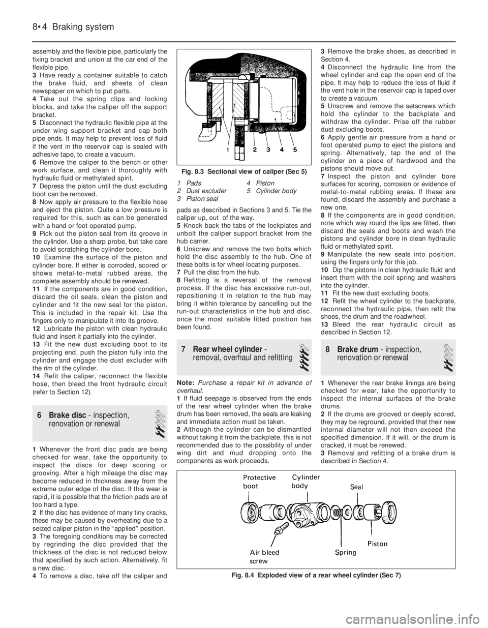
Fig. 8.4 Exploded view of a rear wheel cylinder (Sec 7)
1 Pads
2 Dust excluder
3 Piston seal4 Piston
5 Cylinder body
Fig. 8.3 Sectional view of caliper (Sec 5)
Page 85 of 303
9 Master cylinder- removal,
overhaul and refitting
4
Note: Purchase a repair kit in advance of
overhaul.
1The master cylinder is mounted on the front
face of the brake vacuum servo unit (55 and
70 models) or directly to the bulkhead (45
models).
2Cover the front wings with polythene
sheeting or similar material, in case hydraulic
fluid spills onto the paintwork of the car during
removal of the cylinder.
3Detach the leads from the terminals on the
reservoir cap, then unscrew and remove the
cap and float.
4Unscrew the pipe unions and prise the
pipes carefully away from the master cylinder.
Cap the open ends of the pipes and catch any
fluid leaking from the master cylinder in a
suitable container.
5Unscrew the mounting nuts and withdraw
the master cylinder from the bulkhead or from
the servo unit.
6Clean away all external dirt and tip out the
fluid from the reservoir and cylinder body.
7The fluid reservoirs need not be removed
from the master cylinder but if they are, renew
the rubber sealing collars when refitting.
8Grip the master cylinder in a vice, then
unscrew and remove the end plug. Catch the
coil spring.
9Using a thin rod, apply pressure to the end
of the primary piston then unscrew and
remove the two stop bolts and sealing
washers.
10The internal piston assemblies with seals
and springs can now be pushed out of the
cylinder body. Keep all the components in
Braking system 8•5
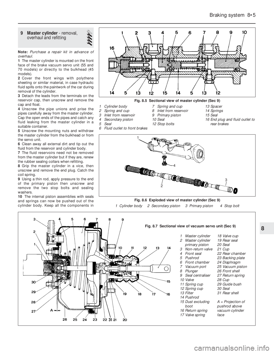
Fig. 8.5 Sectional view of master cylinder (Sec 9)
1 Cylinder body
2 Spring and cup
3 Inlet from reservoir
4 Secondary piston
5 Seal
6 Fluid outlet to front brakes7 Spring and cup
8 Inlet from reservoir
9 Primary piston
10 Seal
12 Stop bolts13 Spacer
14 Springs
15 Seal
16 End plug and fluid outlet to
rear brakes
Fig. 8.6 Exploded view of master cylinder (Sec 9)
1 Cylinder body 2 Secondary piston 3 Primary piston 4 Stop bolt
8Fig. 8.7 Sectional view of vacuum servo unit (Sec 9)
1 Master cylinder
2 Master cylinder
primary piston
3 Non-return valve
4 Front seal
5 Pushrod
6 Front chamber
7 Vacuum port
8 Plunger
9 Seal centraliser
10 Valve
11 Spring cup
12 Spring cup
13 Filter
14 Pushrod
15 Dust excluding
boot
16 Return spring
17 Valve spring18 Valve cup
19 Rear seal
20 Seal
21 Cup
22 Rear chamber
23 Backing plate
24 Diaphragm
25 Vacuum piston
26 Front shell
27 Return spring
28 Cup
29 Guide bush
30 Seal
31 Rear shell
A = Projection of
pushrod above
vacuum cylinder
face
2
3
1
4
Page 86 of 303
their originally fitted sequence and note in
which direction the seal lips are located.
11Inspect the surfaces of the piston and
cylinder bore. If scoring, corrosion or
metal-to-metal rubbing areas are evident,
renew the master cylinder complete.
12If the components are in good condition,
discard the oil seals and manipulate the new
ones into position, using the fingers only.
13Refit by reversing the removal operations;
apply pressure to the piston ends so that the
stop bolts can be fitted, then tighten the end
plug. Make sure that the grooves in the
pistons engage in the stop bolts.
14Before refitting the master cylinder to the
servo, measure the projection of the servo
piston pushrod. When the master cylinder is
fitted, there must be a clearance (see A in
Fig. 8.7) between the end of the pushrod and
the primary piston end face of between 0.825
and 1.025 mm (0.03 and 0.04 in). A depth
gauge will be required for these
measurements, the reference point being the
mating surfaces of the master cylinder and the
vacuum servo.
15Alter the adjusting screw on the servo as
necessary and lock it by applying locking fluid
to the threads on completion.16Bolt the master cylinder to the vacuum
servo or bulkhead, then reconnect the
pipelines and reservoir cap leads.
17Bleed the complete hydraulic system, as
described in Section 12.
10 Pressure regulating valve
3
1The pressure regulating valve is a load
proportioning valve which restricts the
hydraulic pressure to the rear brakes
according to car weight during heavy
applications of the brake pedal. This prevents
the rear wheels locking.
2A faulty or non-operational valve should be
renewed complete, no repair being possible.
3To remove the valve, unscrew the pipe
unions and disconnect the hydraulic pipes
from the valve. Cap the ends of the pipes to
prevent loss of fluid.
4Unbolt the valve mounting bracket,
withdraw it and disconnect the tension spring
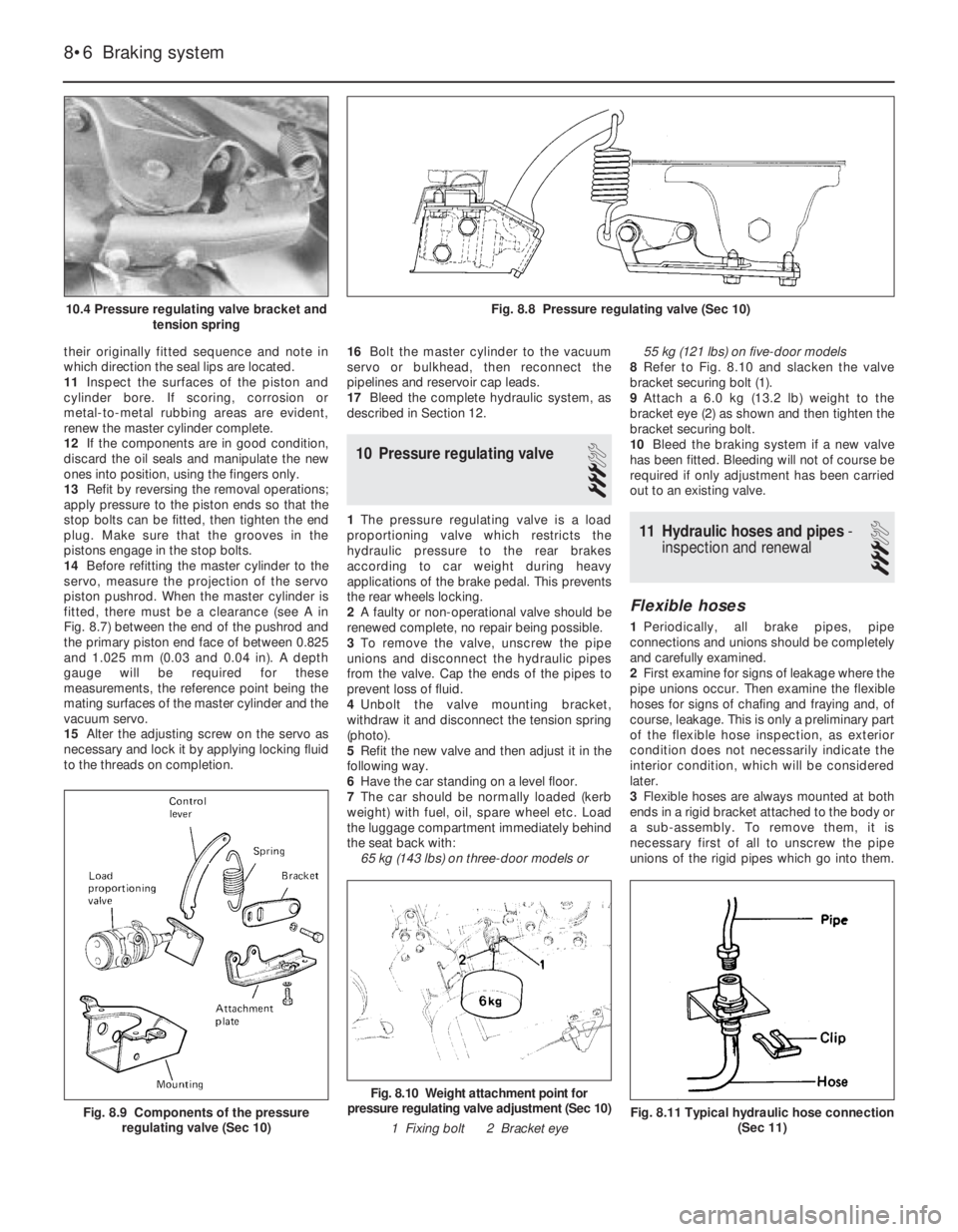
(photo).
5Refit the new valve and then adjust it in the
following way.
6Have the car standing on a level floor.
7The car should be normally loaded (kerb
weight) with fuel, oil, spare wheel etc. Load
the luggage compartment immediately behind
the seat back with:
65 kg (143 lbs) on three-door models or 55 kg (121 lbs) on five-door models
8Refer to Fig. 8.10 and slacken the valve
bracket securing bolt (1).
9Attach a 6.0 kg (13.2 lb) weight to the
bracket eye (2) as shown and then tighten the
bracket securing bolt.
10Bleed the braking system if a new valve
has been fitted. Bleeding will not of course be
required if only adjustment has been carried
out to an existing valve.11 Hydraulic hoses and pipes-
inspection and renewal
3
Flexible hoses
1Periodically, all brake pipes, pipe
connections and unions should be completely
and carefully examined.
2First examine for signs of leakage where the
pipe unions occur. Then examine the flexible
hoses for signs of chafing and fraying and, of
course, leakage. This is only a preliminary part
of the flexible hose inspection, as exterior
condition does not necessarily indicate the
interior condition, which will be considered
later.
3Flexible hoses are always mounted at both
ends in a rigid bracket attached to the body or
a sub-assembly. To remove them, it is
necessary first of all to unscrew the pipe
unions of the rigid pipes which go into them.
8•6 Braking system
Fig. 8.11 Typical hydraulic hose connection
(Sec 11)
Fig. 8.10 Weight attachment point for
pressure regulating valve adjustment (Sec 10)
1 Fixing bolt 2 Bracket eye
Fig. 8.9 Components of the pressure
regulating valve (Sec 10)
Fig. 8.8 Pressure regulating valve (Sec 10)10.4 Pressure regulating valve bracket and
tension spring
Page 87 of 303
The hose ends can then be unclipped from
the brackets. The mounting brackets,
particularly on the body frame, are not very
heavy gauge and care must be taken not to
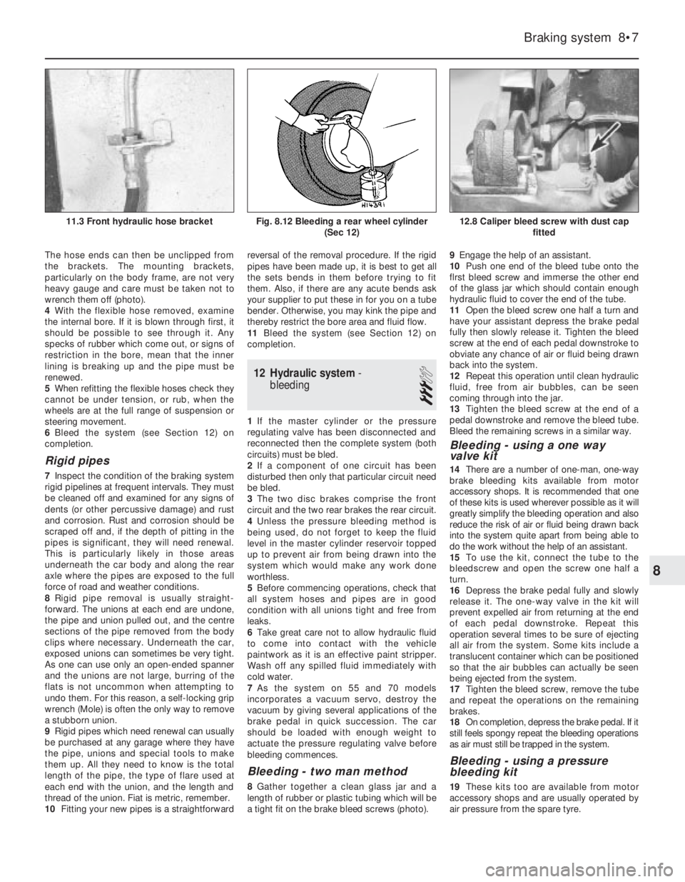
wrench them off (photo).
4With the flexible hose removed, examine
the internal bore. If it is blown through first, it
should be possible to see through it. Any
specks of rubber which come out, or signs of
restriction in the bore, mean that the inner
lining is breaking up and the pipe must be
renewed.
5When refitting the flexible hoses check they
cannot be under tension, or rub, when the
wheels are at the full range of suspension or
steering movement.
6Bleed the system (see Section 12) on
completion.
Rigid pipes
7Inspect the condition of the braking system
rigid pipelines at frequent intervals. They must
be cleaned off and examined for any signs of
dents (or other percussive damage) and rust
and corrosion. Rust and corrosion should be
scraped off and, if the depth of pitting in the
pipes is significant, they will need renewal.
This is particularly likely in those areas
underneath the car body and along the rear
axle where the pipes are exposed to the full
force of road and weather conditions.
8Rigid pipe removal is usually straight-
forward. The unions at each end are undone,
the pipe and union pulled out, and the centre
sections of the pipe removed from the body
clips where necessary. Underneath the car,
exposed unions can sometimes be very tight.
As one can use only an open-ended spanner
and the unions are not large, burring of the
flats is not uncommon when attempting to
undo them. For this reason, a self-locking grip
wrench (Mole) is often the only way to remove
a stubborn union.
9Rigid pipes which need renewal can usually
be purchased at any garage where they have
the pipe, unions and special tools to make
them up. All they need to know is the total
length of the pipe, the type of flare used at
each end with the union, and the length and
thread of the union. Fiat is metric, remember.
10Fitting your new pipes is a straightforwardreversal of the removal procedure. If the rigid
pipes have been made up, it is best to get all
the sets bends in them before trying to fit
them. Also, if there are any acute bends ask
your supplier to put these in for you on a tube
bender. Otherwise, you may kink the pipe and
thereby restrict the bore area and fluid flow.
11Bleed the system (see Section 12) on
completion.
12 Hydraulic system-
bleeding
3
1If the master cylinder or the pressure
regulating valve has been disconnected and
reconnected then the complete system (both
circuits) must be bled.
2If a component of one circuit has been
disturbed then only that particular circuit need
be bled.
3The two disc brakes comprise the front
circuit and the two rear brakes the rear circuit.
4Unless the pressure bleeding method is
being used, do not forget to keep the fluid
level in the master cylinder reservoir topped
up to prevent air from being drawn into the
system which would make any work done
worthless.
5Before commencing operations, check that
all system hoses and pipes are in good
condition with all unions tight and free from
leaks.
6Take great care not to allow hydraulic fluid
to come into contact with the vehicle
paintwork as it is an effective paint stripper.
Wash off any spilled fluid immediately with
cold water.
7As the system on 55 and 70 models
incorporates a vacuum servo, destroy the
vacuum by giving several applications of the
brake pedal in quick succession. The car
should be loaded with enough weight to
actuate the pressure regulating valve before
bleeding commences.
Bleeding - two man method
8Gather together a clean glass jar and a
length of rubber or plastic tubing which will be
a tight fit on the brake bleed screws (photo).9Engage the help of an assistant.
10Push one end of the bleed tube onto the
flrst bleed screw and immerse the other end
of the glass jar which should contain enough
hydraulic fluid to cover the end of the tube.
11Open the bleed screw one half a turn and
have your assistant depress the brake pedal
fully then slowly release it. Tighten the bleed
screw at the end of each pedal downstroke to
obviate any chance of air or fluid being drawn
back into the system.
12Repeat this operation until clean hydraulic
fluid, free from air bubbles, can be seen
coming through into the jar.
13Tighten the bleed screw at the end of a
pedal downstroke and remove the bleed tube.
Bleed the remaining screws in a similar way.
Bleeding - using a one way
valve kit
14There are a number of one-man, one-way
brake bleeding kits available from motor
accessory shops. It is recommended that one
of these kits is used wherever possible as it will
greatly simplify the bleeding operation and also
reduce the risk of air or fluid being drawn back
into the system quite apart from being able to
do the work without the help of an assistant.
15To use the kit, connect the tube to the
bleedscrew and open the screw one half a
turn.
16Depress the brake pedal fully and slowly
release it. The one-way valve in the kit will
prevent expelled air from returning at the end
of each pedal downstroke. Repeat this
operation several times to be sure of ejecting
all air from the system. Some kits include a
translucent container which can be positioned
so that the air bubbles can actually be seen
being ejected from the system.
17Tighten the bleed screw, remove the tube
and repeat the operations on the remaining
brakes.
18On completion, depress the brake pedal. If it
still feels spongy repeat the bleeding operations
as air must still be trapped in the system.
Bleeding - using a pressure
bleeding kit
19These kits too are available from motor
accessory shops and are usually operated by
air pressure from the spare tyre.
Braking system 8•7
12.8 Caliper bleed screw with dust cap
fittedFig. 8.12 Bleeding a rear wheel cylinder
(Sec 12)11.3 Front hydraulic hose bracket
8
Page 88 of 303
20By connecting a pressurised container to
the master cylinder fluid reservoir, bleeding is
then carried out by simply opening each bleed
screw in turn and allowing the fluid to run out,
rather like turning on a tap, until no air is
visible in the expelled fluid.
21By using this method, the large reserve of
hydraulic fluid provides a safeguard against
air being drawn into the master cylinder
during bleeding which often occurs if the fluid
level in the reservoir is not maintained.
22Pressure bleeding is particularly effective
when bleeding “difficult” systems or when
bleeding the complete system at time of
routine fluid renewal.
All methods
23When bleeding is completed, check and
top up the fluid level in the master cylinder
reservoir.
24Check the feel of the brake pedal. If it
feels at all spongy, air must still be present in
the system and further bleeding is indicated.
Failure to bleed satisfactorily after a
reasonable period of the bleeding operation,
may be due to worn master cylinder seals.
25Discard brake fluid which has been
expelled. lt is almost certain to be
contaminated with moisture, air and dirt
making it unsuitable for further use. Clean
fluid should always be stored in an airtight
container as it absorbs moisture readily
(hygroscopic) which lowers its boiling point
and could affect braking performance under
severe conditions.
13 Vacuum servo unit-
description
A vacuum servo unit is fitted into the brake
hydraulic circuit on 55 and 70 models in series
with the master cylinder, to provide assistance
to the driver when the brake pedal is
depressed. This reduces the effort required by
the driver to operate the brakes under all
braking conditions.
The unit operates by vacuum obtained from
the induction manifold and comprises basically
a booster diaphragm and non-return valve. The
servo unit and hydraulic master cylinder are
connected together so that the servo unit
piston rod acts as the master cylinder pushrod.
The driver’s braking effort is transmitted
through another pushrod to the servo unit
piston and its built-in control system. The servo
unit piston does not fit tightly into the cylinder,
but has a strong diaphragm to keep its edges
in constant contact with the cylinder wall, so
assuring an air tight seal between the two
parts. The forward chamber is held under
vacuum conditions created in the inlet manifold
of the engine and, during periods when the
brake pedal is not in use, the controls open a
passage to the rear chamber so placing it
under vacuum conditions as well. When the
brake pedal is depressed, the vacuum passageto the rear chamber is cut off and the chamber
opened to atmospheric pressure. The
consequent rush of air pushes the servo piston
forward in the vacuum chamber and operates
the main pushrod to the master cylinder.
The controls are designed so that
assistance is given under all conditions and,
when the brakes are not required, vacuum in
the rear chamber is established when the
brake pedal is released. All air from the
atmosphere entering the rear chamber is
passed through a small air filter.
Under normal operating conditions, the
vacuum servo unit is very reliable and does
not require overhaul except at very high
mileages. In this case, it is far better to obtain
a service exchange unit, rather than repair the
original unit.
It is emphasised that the servo unit assists
in reducing the braking effort required at the
foot pedal and in the event of its failure, the
hydraulic braking system is in no way affected
except that the need for higher pressures will
be noticed.
14 Vacuum servo unit-
servicing and testing
1Regularly, check that the vacuum hose
which runs between the servo unit and the
inlet manifold is in good condition and is a
tight fit at both ends.
2If broken or badly clogged, renew the air
filter which is located around the brake pedal
push rod. Access to this is obtained by
disconnecting the pushrod from the
cross-shaft or pedal arm, withdrawing the
pushrod, dust excluding boot and end cap.
3If the new filter is cut diagonally from its
centre hole, future renewal can be carried out
without the need for disconnection of the
pushrod.
4If the efficiency of the servo unit is suspect,
it can be checked out in the following way.
5Run the engine, then switch off the ignition.
Depress the footbrake pedal; the distinctive
in-rush of air into the servo should be clearly
heard. It should be possible to repeat this
operation several times before the vacuum in
the system is exhausted.
6Start the engine and have an assistant
apply the footbrake pedal and hold it down.
Disconnect the vacuuum hose from the servo.
There should not be any in-rush of air into the
servo through the connecting stub. lf there is,
the servo diaphragm is probably faulty. During
this test, expect the engine to idle roughly,
unless the open end of the hose to the inlet
manifold is plugged. Reconnect the hose.
7With the engine off, depress the brake
pedal fully. Start the engine with the brake
pedal still depressed; the pedal should be felt
to go down fractionally.
8If the results of these tests are not
satisfactory, remove the unit and fit a new one
as described in the next Section.
15 Vacuum servo unit-
removal and refitting
3
1Syphon as much fluid as possible out of the
master cylinder reservolr.
2Disconnect electrical leads from the
terminals in the reservoir cap then uncouple
the rigid pipelines from the master cylinder
body. Be prepared to catch leaking fluid and
plug the open ends of the pipelines.
3The master cylinder can be unbolted now
from the servo unit, or detached later when
the complete assembly is withdrawn.
4Working inside the car, disconnect the
servo pushrod from the pedal then remove the
servo mounting nuts.
5Withdraw the servo assembly into the
engine compartment, then remove it to the
bench. lf the master cylinder is still attached,
cover the wings with protective sheeting, in
case brake fluid is spilled during removal.
6Refitting is a reversal of the removal
process, but adjust the pushrod clearance as
described in Section 9. On completion of
refitting, bleed the complete hydraulic system
as described in Section 12. Note: Where the
help of an assistant is available, the servo
pushrod need not be disconnected from the
pedal. The rod is a sliding fit in the servo and
the servo can be simply pulled off the rod.
Refitting without having disconnected the rod
from the pedal can be difficult unless the help
of an assistant is available.
16 Handbrake- adjustment
1
Adjustment is normally automatic, by the
movement of the rear brake shoes on their
automatic adjusters.
However, owing to cable stretch,
supplementary adjustment is occasionally
required at the control lever adjuster nut. The
need for this adjustment is usually indicated
by excessive movement of the control lever
when fully applied.
1The rear brakes should be fully applied
when the handbrake control lever has been
pulled over four or five notches.
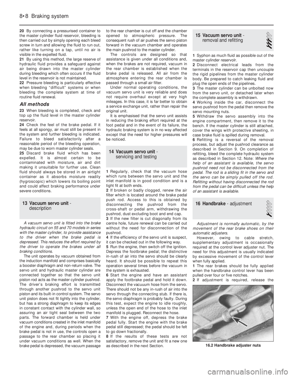
2If adjustment is required, release the
8•8 Braking system
16.2 Handbrake adjuster nuts
Page 89 of 303
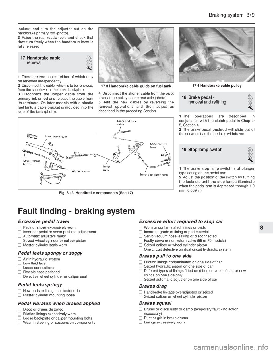
locknut and turn the adjuster nut on the
handbrake primary rod (photo).
3Raise the rear roadwheels and check that
they turn freely when the handbrake lever is
fully released.
17 Handbrake cable-
renewal
1
1There are two cables, either of which may
be renewed independently
2Disconnect the cable, which is to be renewed,
from the shoe lever at the brake backplate.
3Disconnect the longer cable from the
primary link or rod and release the cable from
its retainers. On later models with a plastic
fuel tank, a cable bracket is moulded into the
side of the tank (photo).4Disconnect the shorter cable from the pivot
lever at the pulley on the rear axle (photo).
5Refit the new cables by reversing the
removal operations and then adjust as
described in the preceding Section.
18 Brake pedal-
removal and refitting
1
1The operations are described in
conjunction with the clutch pedal in Chapter
5, Section 4.
2The brake pedal pushrod will slide out of
the servo unit as the pedal is withdrawn.
19 Stop lamp switch
1
1The brake stop lamp switch is of plunger
type acting on the pedal arm.
2Adjust the position of the switch by turning
the locknuts until the stop lamps illuminate
when the pedal arm is depressed through 1.0
mm (0.039 in).
Braking system 8•9
Fig. 8.13 Handbrake components (Sec 17)
17.4 Handbrake cable pulley17.3 Handbrake cable guide on fuel tank
8
Fault finding - braking system
Excessive pedal travel
m mPads or shoes excessively worn
m mIncorrect pedal or servo pushrod adjustment
m mAutomatic adjusters faulty
m mSeized wheel cylinder or caliper piston
m mMaster cylinder seals worn
Pedal feels spongy or soggy
m
mAir in hydraulic system
m mLow fluid level
m mLoose connections
m mFlexible hose perished
m mDefective wheel cylinder or caliper seal
Pedal feels springy
m
mNew pads or linings not bedded-in
m mMaster cylinder mounting loose
Pedal vibrates when brakes applied
m
mDiscs or drums distorted
m mFriction linings excessively worn
m mLoose backplate or caliper mounting bolts
m mWear in steering or suspension components
Excessive effort required to stop car
m
mWorn or contaminated linings or pads
m mIncorrect grade of lining or pad material
m mServo vacuum hose leaking or disconnected
m mFaulty servo or non-return valve (55 or 70 models)
m mSeized caliper or wheel cylinder piston
m mOne circuit defective on dual circuit hydraulic system
Brakes pull to one side
m
mFriction linings contaminated on one side of car
m mSeized hydraulic piston on one side of car
m mDifferent types of linings fitted on different sides of car, or new
linings on one side only
m mSeized automatic adjuster on one side of car
Brakes drag
m
mHandbrake linkage overadjusted or seized
m mSeized caliper or wheel cylinder piston
Brakes squeal
m
mDrums or discs rusty or damp (temporary fault - no action
necessary)
m mDust or grit in brake drums
m mLinings excessively worn
Page 101 of 303

3The centralised door locking system can
operate independently of the key.
4To gain access to the lock solenoid and
linkage, remove the front door trim panel as
described in Chapter 12.
5Disconnect the battery negative lead.
6Disconnect the electrical wiring plugs from
the solenoid within the door cavity.
7Disconnect the solenoid from the lock lever
by removing the clip.
8Unscrew the two bolts which secure the
solenoid to the door and remove it.
9Renew the solenoid or switch as necessary.
10Refitting is a reversal of removal.
11Refer to Section 10 for details of system
fuses and relays.
33 Economy gauge
(Econometer)
2
1This device is fitted to ES (energy saving)
models and indicates to the driver the fuel
consumption (in litres per 100 km) coupled
with a needle which moves over coloured
sections of a dial to make the driver aware
that his method of driving is either conducive
to high or low fuel consumption. Refer to
Chapter 3, Section 16.
2The device is essentially a vacuum gauge
which also incorporates a warning lamp to
indicate to the driver when a change of gear is
required.
3A fuel cut-out valve (see Chapter 3, Sec-
tion 11) is used in conjunction with the
economy gauge so that when the accelerator
pedal is released during a pre-determined
engine speed range, fuel supply to the engine
is stopped, but resumes when the engine
speed falls below the specified range.
LED (light emitter diode)
4The gearchange indicator will only light up
at engine speeds in excess of 2000 rev/min
for vacuum pressures up to 600 mm Hg in 1st,
2nd and 3rd speed gears and for vacuum
pressures up to 676 mm Hg in 4th speedgear. The light will not come on if 5th speed
gear is engaged or if the coolant temperature
is below 55ºC.
5There is a two second delay in the light
coming on to prevent it operating during rapid
acceleration in a low gear.
6If the LED light comes on during
deceleration it should be ignored.
Fault finding
7A faulty economy gauge should be checked
in the following way.
8Refer to Section 21 and remove the
instrument panel.
9Disconnect the economy gauge L
connector and then connect a test lamp
between the BN cable contact and earth. If
the lamp comes on then the gauge supply
circuit is not open. If the lamp does not come
on, check all connections in the supply cable
which comes from the interconnecting unit of
the electrical system, also Fuse No 12.
10Now connect a voltmeter between the
white cable and earth. Check the voltage with
the engine not running, but the ignition
switched on. It should be between 0.7 and
0.9 volt. If the reading varies considerably
from that specified, check the connections
between the economy gauge and the fuel
cut-out device control unit. If the fault cannot
be rectified, renew the ignition control unit
(Digiplex system, see Chapter 4).
11Now check the closed throttle valve plate
switch by connecting a voltmeter between the
brown and BN cables of the L connector. With
the valve plate open, there should be no
reading, but with it open, voltage should be
indicated.
12Failure to conform as described will be
due to a faulty earth in the switch or a faulty
fuel cut-out device control unit.
13A further test of the throttle valve plate
switch may be carried out by disconnecting
the multi-plug from the fuel cut-out device
control unit.
14Connect a test lamp to contact 4 (positive
battery terminal). The lamp should come on,
when the engine is idling or the accelerator
released. If it does not, renew the throttle
valve plate switch.15Connect a tachometer to the brown/white
cable contact in the L connector and record
the engine speed with the engine running. If
no reading is obtained, renew the Digiplex
ignition control unit which must be faulty.
34 Check control (warning
module) system
2
1This is fitted into the instrument panel of
certain models to provide a means of
checking the operation of many electrical
circuits and other systems in the interest of
safety. Sensors are used where appropriate.
2The following components are not
monitored by the system, but have separate
warning lamps:
Handbrake “on”
Choke in use
Low engine oil pressure
Battery charge indicator
3The multi-functional electronic device
automatically checks the following functions
whether the engine is running or not:
Coolant level
Disc pad wear
Door closure
Engine oil level
Front parking lamps
Rear foglamps
Stop lamps
4The check information is stored by the
system monitor until the engine is started
when the display panel then indicates the
situation by means of the LEDs (light emitter
diodes) and the general lamp.
5If all functions are in order, the green panel
lamp will come on when the ignition key is
turned and will go out after two to three
seconds.
6If some functions are not in order, then the
red panel lamp will come on also the
appropriate LED.
Sensors - checking
7If a fault signal occurs which is
subsequently found to be incorrect, first
check the wiring connections between the
9•12 Electrical system
Fig. 9.15 Check system control panel (Sec 34)
A Parking lamps
B Coolant levelC Engine oil level
D Door closureE Brake fluid level
F Disc pad wearFig. 9.14 Location of control units (Sec 33)
A Digiplex ignition system control unit
B Fuel cut-out valve control unit
Page 109 of 303
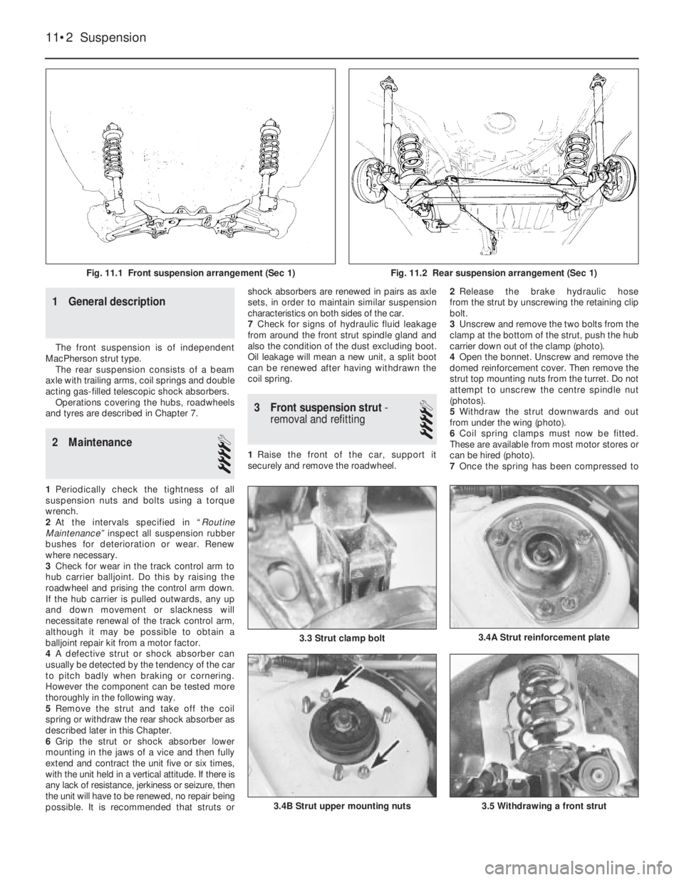
1 General description
The front suspension is of independent
MacPherson strut type.
The rear suspension consists of a beam
axle with trailing arms, coil springs and double
acting gas-filled telescopic shock absorbers.
Operations covering the hubs, roadwheels
and tyres are described in Chapter 7.
2 Maintenance
4
1Periodically check the tightness of all
suspension nuts and bolts using a torque
wrench.
2At the intervals specified in “Routine
Maintenance” inspect all suspension rubber
bushes for deterioration or wear. Renew
where necessary.
3Check for wear in the track control arm to
hub carrier balljoint. Do this by raising the
roadwheel and prising the control arm down.
If the hub carrier is pulled outwards, any up
and down movement or slackness will
necessitate renewal of the track control arm,
although it may be possible to obtain a
balljoint repair kit from a motor factor.
4A defective strut or shock absorber can
usually be detected by the tendency of the car
to pitch badly when braking or cornering.
However the component can be tested more
thoroughly in the following way.
5Remove the strut and take off the coil
spring or withdraw the rear shock absorber as
described later in this Chapter.
6Grip the strut or shock absorber lower
mounting in the jaws of a vice and then fully
extend and contract the unit five or six times,
with the unit held in a vertical attitude. If there is
any lack of resistance, jerkiness or seizure, then
the unit will have to be renewed, no repair being
possible. It is recommended that struts orshock absorbers are renewed in pairs as axle
sets, in order to maintain similar suspension
characteristics on both sides of the car.
7Check for signs of hydraulic fluid leakage
from around the front strut spindle gland and
also the condition of the dust excluding boot.
Oil leakage will mean a new unit, a split boot
can be renewed after having withdrawn the
coil spring.
3 Front suspension strut-
removal and refitting
4
1Raise the front of the car, support it
securely and remove the roadwheel.2Release the brake hydraulic hose
from the strut by unscrewing the retaining clip
bolt.
3Unscrew and remove the two bolts from the
clamp at the bottom of the strut, push the hub
carrier down out of the clamp (photo).
4Open the bonnet. Unscrew and remove the
domed reinforcement cover. Then remove the
strut top mounting nuts from the turret. Do not
attempt to unscrew the centre spindle nut
(photos).
5Withdraw the strut downwards and out
from under the wing (photo).
6Coil spring clamps must now be fitted.
These are available from most motor stores or
can be hired (photo).
7Once the spring has been compressed to
11•2 Suspension
3.5 Withdrawing a front strut3.4B Strut upper mounting nuts
3.4A Strut reinforcement plate3.3 Strut clamp bolt
Fig. 11.1 Front suspension arrangement (Sec 1)Fig. 11.2 Rear suspension arrangement (Sec 1)