1983 FIAT UNO door lock
[x] Cancel search: door lockPage 10 of 303

0•10Routine maintenance
Maintenance is essential for ensuring safety and desirable for the
purpose of getting the best in terms of performance and economy
from the car. Over the years the need for periodic lubrication has been
greatly reduced if not totally eliminated. This has unfortunately tended
to lead some owners to think that because no such action is required
the items either no longer exist or will last forever. This is certainly not
the case; it is essential to carry out regular visual examinations as
comprehensively as possible in order to spot any possible defects at
an early stage before they develop into major and expensive repairs.
For information applicable to later models, see Supplement.
Every 250 miles (400 km), weekly,
or before a long journey
m mCheck engine oil level
m mCheck brake reservoir fluid level
m mCheck tyre pressures
m mCheck operation of all lights and horn
m mTop up washer fluid reservoirs, adding a screen
wash, and check operation of washers and wipers
m mCheck coolant level
m mCheck battery electrolyte level
Every 6000 miles (10 000 km)
or six months, whichever comes first
m mRenew engine oil and filter (Chapter 1, Section 2)
m mCheck drivebelt tension (Chapter 2, Section 8)
m mCheck carburettor idle speed and mixture
adjustments (Chapter 3)
m mCheck contact points and dwell angle (mechanical
breaker distributors) (Chapter 4, Section 3)
m mCheck tyre tread wear (Chapter 7, Section 7)
m mCheck disc pads for wear (Chapter 8, Section 3)
Every 36 000 miles (60 000 km)
or three years, whichever comes first
m mRenew the timing belt - 1116 and 1299/1301 cc
(Chapter 1, Section 28)
m mCheck exhaust system for corrosion (Chapter 3,
Section 19)
m mRenew contact breaker points and adjust dwell
angle (mechanical breaker distributors) (Chapter 4,
Section 3)
m mCheck and adjust ignition timing (Chapter 4,
Section 4)
m mRenew spark plugs (Chapter 4, Section 11)
m mCheck clutch adjustment (Chapter 5, Section 2)
m mCheck transmission oil level (Chapter 6, Section 2)
m mCheck driveshaft and steering rack gaiters for splits
(Chapters 7 and 10)
m mCheck rear brake shoe linings for wear (Chapter 8,
Section 4)
m mCheck handbrake travel (Chapter 8, Section 16)
m mCheck headlamp beam alignment (Chapter 9,
Section 17)
m mCheck balljoints for wear (Chapter 10, Section 2)
m mCheck front wheel alignment (Chapter 10, Section 8)
m mCheck suspension bushes for wear (Chapter 11,
Section 2)
m mCheck seat belts for fraying (Chapter 12, Section 23)
m mLubricate controls, hinges and locks
Every 24 000 miles (40 000 km)
or two years, whichever comes first
m mRenew coolant anti-freeze mixture (Chapter 2,
Section 3)
m mRenew transmission oil (Chapter 6, Section 2)
m mRenew brake hydraulic fluid (Chapter 8, Section 12)
m mCheck for underbody corrosion and clean out door
and sill drain holes (Chapter 12, Section 2)
Every 12 000 miles (20 000 km) or
12 months, whichever comes first
m mCheck and adjust valve clearances (Chapter 1,
Sections 5 and 26)
m mRenew air cleaner element (Chapter 3, Section 2)
Page 86 of 303
their originally fitted sequence and note in
which direction the seal lips are located.
11Inspect the surfaces of the piston and
cylinder bore. If scoring, corrosion or
metal-to-metal rubbing areas are evident,
renew the master cylinder complete.
12If the components are in good condition,
discard the oil seals and manipulate the new
ones into position, using the fingers only.
13Refit by reversing the removal operations;
apply pressure to the piston ends so that the
stop bolts can be fitted, then tighten the end
plug. Make sure that the grooves in the
pistons engage in the stop bolts.
14Before refitting the master cylinder to the
servo, measure the projection of the servo
piston pushrod. When the master cylinder is
fitted, there must be a clearance (see A in
Fig. 8.7) between the end of the pushrod and
the primary piston end face of between 0.825
and 1.025 mm (0.03 and 0.04 in). A depth
gauge will be required for these
measurements, the reference point being the
mating surfaces of the master cylinder and the
vacuum servo.
15Alter the adjusting screw on the servo as
necessary and lock it by applying locking fluid
to the threads on completion.16Bolt the master cylinder to the vacuum
servo or bulkhead, then reconnect the
pipelines and reservoir cap leads.
17Bleed the complete hydraulic system, as
described in Section 12.
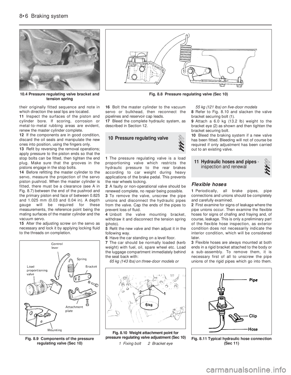
10 Pressure regulating valve
3
1The pressure regulating valve is a load
proportioning valve which restricts the
hydraulic pressure to the rear brakes
according to car weight during heavy
applications of the brake pedal. This prevents
the rear wheels locking.
2A faulty or non-operational valve should be
renewed complete, no repair being possible.
3To remove the valve, unscrew the pipe
unions and disconnect the hydraulic pipes
from the valve. Cap the ends of the pipes to
prevent loss of fluid.
4Unbolt the valve mounting bracket,
withdraw it and disconnect the tension spring
(photo).
5Refit the new valve and then adjust it in the
following way.
6Have the car standing on a level floor.
7The car should be normally loaded (kerb
weight) with fuel, oil, spare wheel etc. Load
the luggage compartment immediately behind
the seat back with:
65 kg (143 lbs) on three-door models or 55 kg (121 lbs) on five-door models
8Refer to Fig. 8.10 and slacken the valve
bracket securing bolt (1).
9Attach a 6.0 kg (13.2 lb) weight to the
bracket eye (2) as shown and then tighten the
bracket securing bolt.
10Bleed the braking system if a new valve
has been fitted. Bleeding will not of course be
required if only adjustment has been carried
out to an existing valve.11 Hydraulic hoses and pipes-
inspection and renewal
3
Flexible hoses
1Periodically, all brake pipes, pipe
connections and unions should be completely
and carefully examined.
2First examine for signs of leakage where the
pipe unions occur. Then examine the flexible
hoses for signs of chafing and fraying and, of
course, leakage. This is only a preliminary part
of the flexible hose inspection, as exterior
condition does not necessarily indicate the
interior condition, which will be considered
later.
3Flexible hoses are always mounted at both
ends in a rigid bracket attached to the body or
a sub-assembly. To remove them, it is
necessary first of all to unscrew the pipe
unions of the rigid pipes which go into them.
8•6 Braking system
Fig. 8.11 Typical hydraulic hose connection
(Sec 11)
Fig. 8.10 Weight attachment point for
pressure regulating valve adjustment (Sec 10)
1 Fixing bolt 2 Bracket eye
Fig. 8.9 Components of the pressure
regulating valve (Sec 10)
Fig. 8.8 Pressure regulating valve (Sec 10)10.4 Pressure regulating valve bracket and
tension spring
Page 90 of 303

9System type . . . . . . . . . . . . . . . . . . . . . . . . . . . . . . . . . . . . . . . . . . . 12 negative earth, battery alternator and pre-engaged starter
Battery
Except 70S . . . . . . . . . . . . . . . . . . . . . . . . . . . . . . . . . . . . . . . . . . . . . . . 30 Ah
70S . . . . . . . . . . . . . . . . . . . . . . . . . . . . . . . . . . . . . . . . . . . . . . . . . . . . 40 Ah
Alternator
Type . . . . . . . . . . . . . . . . . . . . . . . . . . . . . . . . . . . . . . . . . . . . . . . . . . . . Marelli, Valeo or Bosch 45A, 55A or 65A, with integral voltage
regulator
Nominal voltage . . . . . . . . . . . . . . . . . . . . . . . . . . . . . . . . . . . . . . . . . . . 14 V
Minimum brush (wear) length . . . . . . . . . . . . . . . . . . . . . . . . . . . . . . . . . 6.0 mm (0.236 in)
Starter motor
Type . . . . . . . . . . . . . . . . . . . . . . . . . . . . . . . . . . . . . . . . . . . . . . . . . . . . Marelli, Bosch or Femsa pre-engaged
Nominal power . . . . . . . . . . . . . . . . . . . . . . . . . . . . . . . . . . . . . . . . . . . . 0.8 kW or 1.0 kW
Armature shaft endfloat . . . . . . . . . . . . . . . . . . . . . . . . . . . . . . . . . . . . . 0.1 to 0.5 mm (0.0039 to 0.0197 in)
Minimum brush (wear) length . . . . . . . . . . . . . . . . . . . . . . . . . . . . . . . . . 10.0 mm (0.39 in)
Wiper blades
Front . . . . . . . . . . . . . . . . . . . . . . . . . . . . . . . . . . . . . . . . . . . . . . . . . . . . Champion X-4801 (19 in) or X-4503 (18 in)
Rear . . . . . . . . . . . . . . . . . . . . . . . . . . . . . . . . . . . . . . . . . . . . . . . . . . . . Champion X-3303
Chapter 9 Electrical system
For modifications, and information applicable to later models, see Supplement at end of manual
Alternator - maintenance and precautions . . . . . . . . . . . . . . . . . . . . 3
Alternator - overhaul . . . . . . . . . . . . . . . . . . . . . . . . . . . . . . . . . . . . . 5
Alternator - removal and refitting . . . . . . . . . . . . . . . . . . . . . . . . . . . 4
Battery - inspection, charging, removal and refitting . . . . . . . . . . . . 2
Central door locking system . . . . . . . . . . . . . . . . . . . . . . . . . . . . . . . 32
Check control (warning module) system . . . . . . . . . . . . . . . . . . . . . . 34
Cigar lighter . . . . . . . . . . . . . . . . . . . . . . . . . . . . . . . . . . . . . . . . . . . . 36
Clocks - setting . . . . . . . . . . . . . . . . . . . . . . . . . . . . . . . . . . . . . . . . . 35
Courtesy lamp switch . . . . . . . . . . . . . . . . . . . . . . . . . . . . . . . . . . . . 12
Economy gauge (Econometer) . . . . . . . . . . . . . . . . . . . . . . . . . . . . . 33
Electrically-operated front door windows . . . . . . . . . . . . . . . . . . . . . 31
Exterior lamps - bulb renewal . . . . . . . . . . . . . . . . . . . . . . . . . . . . . . 19
Fault finding - electrical system . . . . . . . . . . . . . . See end of Chapter
Fuses and relays . . . . . . . . . . . . . . . . . . . . . . . . . . . . . . . . . . . . . . . . 10
General description . . . . . . . . . . . . . . . . . . . . . . . . . . . . . . . . . . . . . . 1
Headlamp - removal and refitting . . . . . . . . . . . . . . . . . . . . . . . . . . . 18
Headlamp beam - alignment . . . . . . . . . . . . . . . . . . . . . . . . . . . . . . . 17
Headlamp bulb - renewal . . . . . . . . . . . . . . . . . . . . . . . . . . . . . . . . . 16
Heated tailgate window - precautions and repair . . . . . . . . . . . . . . . 29Horns . . . . . . . . . . . . . . . . . . . . . . . . . . . . . . . . . . . . . . . . . . . . . . . . . 15
Instrument panel - dismantling . . . . . . . . . . . . . . . . . . . . . . . . . . . . . 22
Instrument panel - removal and refitting . . . . . . . . . . . . . . . . . . . . . . 21
Interior lamps - bulb renewal . . . . . . . . . . . . . . . . . . . . . . . . . . . . . . 20
Radio/cassette - fitting . . . . . . . . . . . . . . . . . . . . . . . . . . . . . . . . . . . 30
Rocker and push-button switches . . . . . . . . . . . . . . . . . . . . . . . . . . 13
Speedometer drive cable - renewal . . . . . . . . . . . . . . . . . . . . . . . . . 23
Starter motor - description and testing . . . . . . . . . . . . . . . . . . . . . . . 7
Starter motor - overhaul . . . . . . . . . . . . . . . . . . . . . . . . . . . . . . . . . . 9
Starter motor - removal and refitting . . . . . . . . . . . . . . . . . . . . . . . . . 8
Steering column combination switch . . . . . . . . . . . . . . . . . . . . . . . . 11
Tailgate contacts . . . . . . . . . . . . . . . . . . . . . . . . . . . . . . . . . . . . . . . . 14
Tailgate wiper blade and arm - removal and refitting . . . . . . . . . . . . 26
Tailgate wiper motor - removal and refitting . . . . . . . . . . . . . . . . . . . 27
Voltage regulator . . . . . . . . . . . . . . . . . . . . . . . . . . . . . . . . . . . . . . . . 6
Washer system . . . . . . . . . . . . . . . . . . . . . . . . . . . . . . . . . . . . . . . . . 28
Windscreen wiper blade and arm - removal and refitting . . . . . . . . . 24
Windscreen wiper motor - removal and refitting . . . . . . . . . . . . . . . . 25
9•1
Specifications Contents
Easy,suitable for
novice with little
experienceFairly easy,suitable
for beginner with
some experienceFairly difficult,
suitable for competent
DIY mechanic
Difficult,suitable for
experienced DIY
mechanicVery difficult,
suitable for expert DIY
or professional
Degrees of difficulty
54321
Page 91 of 303

1 General description
The electrical system is of 12 volt negative
earth type and employs a belt-driven
alternator and a pre-engaged type starter
motor.
The models in the range are all adequately
equipped with electrical accessories, while SX
versions also have power windows and
centralised door locking plus a check control
system (Section 34).
2 Battery- inspection, charging,
removal and refitting
2
1The battery is of maintenance-free type and
under normal circumstances, no topping up
will be required, but regularly check that the
electrolyte level is between the minimum and
maximum lines on the translucent battery
casing.
2If the electrolyte level does drop below theminimum line, suspect a leak in the battery
casing or that the alternator is overcharging. If
the latter is the case, rectify the alternator fault
and then prise out the two rectangular plugs
from the top of the battery and top up with
distilled or purified water.
3Always keep the battery terminals clean
and smear them with petroleum jelly to
prevent corrosion.
4The battery will normally be kept fully
charged by the alternator, but it is possible for
the battery to become discharged if the daily
mileage is very low with much use being
made of the starter and electrical accessories.
5When the battery begins to deteriorate with
age it may also require a boost from a mains
charger.
6Disconnect both battery leads before
connecting the mains charger. 7To remove the battery from the car, first
disconnect the leads from the battery
terminals (earth first) and then unscrew the
securing clamp from the casing projection at
the base of the casing (photo).
8Lift the battery from its mounting platform.
Refitting is a reversal of removal. Reconnect
the earth cable last.
Fuses
Circuit protected Fuse rating (A)
1 Stop lamps, direction indicator lamps, instrument panel warning
lamps, tachometer economy gauge, check control system . . . . . . 10
2 Windscreen wiper and washer, rear screen wiper/washer, check
system panel illumination . . . . . . . . . . . . . . . . . . . . . . . . . . . . . . . . 20
3 Left front parking, right rear tail lamp, cigar lighter illumination,
heater control and clock, digital clock illumination . . . . . . . . . . . . . 7.5
4 Right front parking lamp and left rear tail lamp, instrument panel
illumination and rear number plate lamp . . . . . . . . . . . . . . . . . . . . . 7.5
5 Left-hand dipped headlamp, rear foglamps . . . . . . . . . . . . . . . . . . 10
6 Right-hand dipped headlamp . . . . . . . . . . . . . . . . . . . . . . . . . . . . . 10
7 Left-hand headlamp (main beam) . . . . . . . . . . . . . . . . . . . . . . . . . . 10
8 Right-hand headlamp (main beam) . . . . . . . . . . . . . . . . . . . . . . . . . 10
9 Engine cooling fan and horn (Comfort) . . . . . . . . . . . . . . . . . . . . . . 25
10 Heater booster fan, digital clock map reading lamp . . . . . . . . . . . . 20
11 Heated tailgate glass . . . . . . . . . . . . . . . . . . . . . . . . . . . . . . . . . . . 20
12 Courtesy lamps, cigar lighter, radio power feed, disc pad
sensors, economy gauge (ES models) . . . . . . . . . . . . . . . . . . . . . . 10
13 Hazard warning lamps . . . . . . . . . . . . . . . . . . . . . . . . . . . . . . . . . . 10
14 Spare (Comfort), Horn (Super) . . . . . . . . . . . . . . . . . . . . . . . . . . . . 20
BulbsWattage
Headlamp . . . . . . . . . . . . . . . . . . . . . . . . . . . . . . . . . . . . . . . . . . . . . . . . 40/45 or Halogen H4 60/55
Front parking . . . . . . . . . . . . . . . . . . . . . . . . . . . . . . . . . . . . . . . . . . . . . 5
Side repeater . . . . . . . . . . . . . . . . . . . . . . . . . . . . . . . . . . . . . . . . . . . . . 5
Tail . . . . . . . . . . . . . . . . . . . . . . . . . . . . . . . . . . . . . . . . . . . . . . . . . . . . 5
Stop . . . . . . . . . . . . . . . . . . . . . . . . . . . . . . . . . . . . . . . . . . . . . . . . . . . . 21
Reversing . . . . . . . . . . . . . . . . . . . . . . . . . . . . . . . . . . . . . . . . . . . . . . . . 21
Rear foglamp . . . . . . . . . . . . . . . . . . . . . . . . . . . . . . . . . . . . . . . . . . . . . 21
Direction indicator . . . . . . . . . . . . . . . . . . . . . . . . . . . . . . . . . . . . . . . . . 21
Rear number plate . . . . . . . . . . . . . . . . . . . . . . . . . . . . . . . . . . . . . . . . . 5
Courtesy lamp (roof) . . . . . . . . . . . . . . . . . . . . . . . . . . . . . . . . . . . . . . . . 10
Courtesy lamp (pillar) . . . . . . . . . . . . . . . . . . . . . . . . . . . . . . . . . . . . . . . 5
Warning and indicator . . . . . . . . . . . . . . . . . . . . . . . . . . . . . . . . . . . . . . Wedge base
Torque wrench settingsNm lbf ft
Alternator mounting and adjustment nuts . . . . . . . . . . . . . . . . . . . . . . . 50 87
Starter motor bolts . . . . . . . . . . . . . . . . . . . . . . . . . . . . . . . . . . . . . . . . . 48 35
9•2 Electrical system
2.7 Battery clamp
If battery terminal corrosion
has occurred, it may be
neutralised by applying
sodium bicarbonate or
household ammonia.
Page 94 of 303

8Withdraw the solenoid and yoke off the
armature and from the drive end bracket.
Note the steel and fibre washers and the
shims on the armature shaft (photo).
9Extract the split pin and tap out the
engagement lever pivot pin.
10Pull the rubber packing piece from the
drive end bracket.
11Withdraw the armature with solenoid
plunger, coil spring and engagement lever.
12Clean the commutator with a fuel soaked
rag or very fine glass paper. Do not undercut
the mica insulators on the commutator.
Drive
13To remove the drive assembly from the
armature shaft, use a piece of tubing to tap
the stop collar down the shaft to expose the
snap ring. Remove the snap ring and stop
collar and slide the drive assembly from the
shaft.
14Refitting is a reversal of removal, but use a
new snap ring to secure the drive to the
armature shaft.
10 Fuses and relays
1
1The fuse box is located under the left-hand
side of the facia panel and is held in place by
two hand screws (photo).2The fuses and the circuits protected are
identified by symbols. Refer also to Specifi-
cations.
3If a fuse blows, always renew it with one of
identical rating. If the new fuse blows
immediately, find the cause before renewing
the fuse for the second time. This is usually
due to defective wiring insulation causing a
short circuit.
4Never substitute a piece of wire or other
makeshift device for a proper fuse.
5Various relays are plugged into the fuse
block and include those for the heated rear
screen, heater and horns.
6On cars fitted with power-operated front
windows and centralised door locking, the
fuses and relays for these circuits are
mounted separately under the right-hand side
of the facia panel.
7The relay (flasher unit) for the direction
indicators and hazard warning lamps is
located on the lower part of the
steering column combination switch and
is accessible after removing the column
shroud.
11 Steering column
combination switch
1
1Disconnect the battery negative lead.
2Remove the steering column shrouds. 3The switch can be removed without
having to take off the steering wheel, but for
clarity, the photographs show the wheel
removed.
4Unscrew the switch clamp nuts, disconnect
the wiring plug and remove the switch from
the steering column (photo).
5Refitting is a reversal of removal, but make
sure that the activating projections on the
steering wheel hub engage correctly with the
switches.
12 Courtesy lamp switch
1
1These are located in and secured to the
body pillars with a single screw (photo).
2Disconnect the battery negative lead.
3Extract the switch screw and withdraw the
switch.
4If the leads are to be disconnected, tape
them to the pillar to prevent them from
slipping inside.
5Refitting is a reversal of removal. Apply
petroleum jelly to the switch contacts to
prevent corrosion.
13 Rocker and push-button
switches
1
1These are mounted in panels on each side
of the instrument panel.
2Disconnect the battery negative lead.
3Prise off the instrument panel hood cover.
This is held in place by clips. The careful use
of a screwdriver will assist in releasing them
(see Section 21).
4Extract the switch panel fixing screws.
These compress spring clips which in turn
secure the switch panel (photo).
5Withdraw the switch panel until the wiring
plugs can be disconnected. Record the
location of the plugs before disconnecting
Electrical system 9•5
11.4 Unscrewing steering column switch
clamp nut
1 Direction indicator flasher unit (relay)10.1 Fuse block (later models)
1 Horn relay
2 Heated tailgate window relay9.8 Starter motor dismantled
13.4 Switch panel screw12.1 Courtesy lamp switch
9
Page 100 of 303

paintwork should the drill slip. Three methods
of making the hole are in use:
a) Use a hole saw in the electric drill. This is,
in effect, a circular hacksaw blade
wrapped round a former with a centre
pilot drill.
b) Use a tank cutter which also has cutting
teeth, but is made to shear the metal by
tightening with an Allen key.
c) The hard way of drilling out the circle is
using a small drill, say 1/8 in (3 mm), so
that the holes overlap. The centre metal
drops out and the hole is finished with
round and half-round files.
14Whichever method is used, the burr is
removed from the body metal and paint
removed from the underside. The aerial is fitted
tightly ensuring that the earth fixing, usually a
serrated washer, ring or clamp, is making a
solid connection. This earth connection is
important in reducing interference. Cover any
bare metal with primer paint and topcoat, and
follow by underseal if desired.
15Aerial feeder cable routing should avoid
the engine compartment and areas where
stress might occur, eg under the carpet where
feet will be located.Loudspeakers
16A mono speaker may be located under
the facia panel beneath the glovebox.
17Provision is made for twin speakers within
the door tidy bins or under the rear shelf
mountings.
18Speakers should be matched to the
output stage of the equipment, particularly as
regards the recommended impedance. Power
transistors used for driving speakers are
sensitive to the loading placed on them.
31 Electrically-operated front
door windows
3
1The electrically-operated front door
windows are controlled by switches on the
centre console or in the door armrest
(depending on model). The regulator motor
and cable are located within the door cavity.
2To gain access to the assembly, remove
the door trim panel as described in Chap-
ter 12.
3Disconnect the wiring plug (1) (Fig. 9.11).4Release the bolts which connect the power
lift to the glass mounting.
5Remove the bolts which hold the lift
assembly to the door.
6The motor and glass mounting may be
disconnected from the cable guide and sleeve
and any faulty components renewed.
7When refitting the assembly to the door,
make sure that the window glass slides
smoothly before fully tightening the cable
guide bolts. Refer to Section 10 for details of
system fuses and relays.
32 Central door locking system
1
1The doors are locked simultaneously from
the outside by turning the key in either
direction.
2The doors can be locked from inside the car
in the following ways:
All doors locked or unlocked - depress or lift
a front door lock plunger knob.
One rear door locked or unlocked - depress
or lift a rear door lock plunger knob.
Electrical system 9•11
Fig. 9.9 Door speaker mounting (Sec 30)Fig. 9.10 Rear speaker mounting (Sec 30)
Fig. 9.13 Central door locking system
components (Sec 32)Fig. 9.12 Power operated window
components (Sec 31)Fig. 9.11 Power-operated window motor
(Sec 31)
1 Connector plug
1 Electric motor
2 Glass mounting
3 Cable guide4 Cable
5 Cable sleeve1 Solenoid
2 Lock relay lever
3 Link rod4 Exterior handle
lever
9
Page 101 of 303

3The centralised door locking system can
operate independently of the key.
4To gain access to the lock solenoid and
linkage, remove the front door trim panel as
described in Chapter 12.
5Disconnect the battery negative lead.
6Disconnect the electrical wiring plugs from
the solenoid within the door cavity.
7Disconnect the solenoid from the lock lever
by removing the clip.
8Unscrew the two bolts which secure the
solenoid to the door and remove it.
9Renew the solenoid or switch as necessary.
10Refitting is a reversal of removal.
11Refer to Section 10 for details of system
fuses and relays.
33 Economy gauge
(Econometer)
2
1This device is fitted to ES (energy saving)
models and indicates to the driver the fuel
consumption (in litres per 100 km) coupled
with a needle which moves over coloured
sections of a dial to make the driver aware
that his method of driving is either conducive
to high or low fuel consumption. Refer to
Chapter 3, Section 16.
2The device is essentially a vacuum gauge
which also incorporates a warning lamp to
indicate to the driver when a change of gear is
required.
3A fuel cut-out valve (see Chapter 3, Sec-
tion 11) is used in conjunction with the
economy gauge so that when the accelerator
pedal is released during a pre-determined
engine speed range, fuel supply to the engine
is stopped, but resumes when the engine
speed falls below the specified range.
LED (light emitter diode)
4The gearchange indicator will only light up
at engine speeds in excess of 2000 rev/min
for vacuum pressures up to 600 mm Hg in 1st,
2nd and 3rd speed gears and for vacuum
pressures up to 676 mm Hg in 4th speedgear. The light will not come on if 5th speed
gear is engaged or if the coolant temperature
is below 55ºC.
5There is a two second delay in the light
coming on to prevent it operating during rapid
acceleration in a low gear.
6If the LED light comes on during
deceleration it should be ignored.
Fault finding
7A faulty economy gauge should be checked
in the following way.
8Refer to Section 21 and remove the
instrument panel.
9Disconnect the economy gauge L
connector and then connect a test lamp
between the BN cable contact and earth. If
the lamp comes on then the gauge supply
circuit is not open. If the lamp does not come
on, check all connections in the supply cable
which comes from the interconnecting unit of
the electrical system, also Fuse No 12.
10Now connect a voltmeter between the
white cable and earth. Check the voltage with
the engine not running, but the ignition
switched on. It should be between 0.7 and
0.9 volt. If the reading varies considerably
from that specified, check the connections
between the economy gauge and the fuel
cut-out device control unit. If the fault cannot
be rectified, renew the ignition control unit
(Digiplex system, see Chapter 4).
11Now check the closed throttle valve plate
switch by connecting a voltmeter between the
brown and BN cables of the L connector. With
the valve plate open, there should be no
reading, but with it open, voltage should be
indicated.
12Failure to conform as described will be
due to a faulty earth in the switch or a faulty
fuel cut-out device control unit.
13A further test of the throttle valve plate
switch may be carried out by disconnecting
the multi-plug from the fuel cut-out device
control unit.
14Connect a test lamp to contact 4 (positive
battery terminal). The lamp should come on,
when the engine is idling or the accelerator
released. If it does not, renew the throttle
valve plate switch.15Connect a tachometer to the brown/white
cable contact in the L connector and record
the engine speed with the engine running. If
no reading is obtained, renew the Digiplex
ignition control unit which must be faulty.
34 Check control (warning
module) system
2
1This is fitted into the instrument panel of
certain models to provide a means of
checking the operation of many electrical
circuits and other systems in the interest of
safety. Sensors are used where appropriate.
2The following components are not
monitored by the system, but have separate
warning lamps:
Handbrake “on”
Choke in use
Low engine oil pressure
Battery charge indicator
3The multi-functional electronic device
automatically checks the following functions
whether the engine is running or not:
Coolant level
Disc pad wear
Door closure
Engine oil level
Front parking lamps
Rear foglamps
Stop lamps
4The check information is stored by the
system monitor until the engine is started
when the display panel then indicates the
situation by means of the LEDs (light emitter
diodes) and the general lamp.
5If all functions are in order, the green panel
lamp will come on when the ignition key is
turned and will go out after two to three
seconds.
6If some functions are not in order, then the
red panel lamp will come on also the
appropriate LED.
Sensors - checking
7If a fault signal occurs which is
subsequently found to be incorrect, first
check the wiring connections between the
9•12 Electrical system
Fig. 9.15 Check system control panel (Sec 34)
A Parking lamps
B Coolant levelC Engine oil level
D Door closureE Brake fluid level
F Disc pad wearFig. 9.14 Location of control units (Sec 33)
A Digiplex ignition system control unit
B Fuel cut-out valve control unit
Page 114 of 303
12
For dimensions, weights etc. refer to the Introductory Section of this Manual.
Chapter 12 Bodywork
For modifications, and information applicable to later models, see Supplement at end of manual
Bonnet - removal and refitting . . . . . . . . . . . . . . . . . . . . . . . . . . . . . 7
Bonnet - lock and release . . . . . . . . . . . . . . . . . . . . . . . . . . . . . . . . . 8
Centre console - removal and refitting . . . . . . . . . . . . . . . . . . . . . . . 21
Door - dismantling . . . . . . . . . . . . . . . . . . . . . . . . . . . . . . . . . . . . . . . 12
Door - removal and refitting . . . . . . . . . . . . . . . . . . . . . . . . . . . . . . . 13
Door trim panel - removal and refitting . . . . . . . . . . . . . . . . . . . . . . . 11
Facia panel - removal and refitting . . . . . . . . . . . . . . . . . . . . . . . . . . 22
Fixed side window (five-door) - removal and refitting . . . . . . . . . . . . 17
Front bumpers - removal and refitting . . . . . . . . . . . . . . . . . . . . . . . 9
Front seat - removal and refitting . . . . . . . . . . . . . . . . . . . . . . . . . . . 19
Front wing - removal and refitting . . . . . . . . . . . . . . . . . . . . . . . . . . . 10
General description . . . . . . . . . . . . . . . . . . . . . . . . . . . . . . . . . . . . . . 1
Grab handles . . . . . . . . . . . . . . . . . . . . . . . . . . . . . . . . . . . . . . . . . . . 25
Maintenance - bodywork and underframe . . . . . . . . . . . . . . . . . . . . 2Maintenance - upholstery and carpets . . . . . . . . . . . . . . . . . . . . . . . 3
Major body damage - repair . . . . . . . . . . . . . . . . . . . . . . . . . . . . . . . 5
Minor body damage - repair . . . . . . . . . . . . . . . . . . . . . . . . . . . . . . . 4
Opening side window (three-door) - removal and refitting . . . . . . . . 18
Radiator grille - removal and refitting . . . . . . . . . . . . . . . . . . . . . . . . 6
Rear bumpers - removal and refitting . . . . . . . . . . . . . . . . . . . . . . . . 26
Rear seat - removal and refitting . . . . . . . . . . . . . . . . . . . . . . . . . . . . 20
Rear view mirrors . . . . . . . . . . . . . . . . . . . . . . . . . . . . . . . . . . . . . . . 24
Roof rack . . . . . . . . . . . . . . . . . . . . . . . . . . . . . . . . . . . . . . . . . . . . . . 27
Seat belts . . . . . . . . . . . . . . . . . . . . . . . . . . . . . . . . . . . . . . . . . . . . . 23
Sunroof - operation and maintenance . . . . . . . . . . . . . . . . . . . . . . . 28
Tailgate - removal and refitting . . . . . . . . . . . . . . . . . . . . . . . . . . . . . 14
Tailgate glass - removal and refitting . . . . . . . . . . . . . . . . . . . . . . . . 16
Windscreen glass - removal and refitting . . . . . . . . . . . . . . . . . . . . . 15
12•1
Specifications Contents
Easy,suitable for
novice with little
experienceFairly easy,suitable
for beginner with
some experienceFairly difficult,
suitable for competent
DIY mechanic
Difficult,suitable for
experienced DIY
mechanicVery difficult,
suitable for expert DIY
or professional
Degrees of difficulty
54321
1 General description
The Uno is an all steel, welded Hatchback
of unitary construction available in three- or
five-door versions.
Various levels of trim and equipment are
available depending upon model.
Factory fitted options include a sunroof,
central door locking and electrically-operated
front windows.
2 Maintenance-
bodywork and underframe
1
The general condition of a vehicle’s
bodywork is the one thing that significantly
affects its value. Maintenance is easy, but
needs to be regular. Neglect, particularly after
minor damage, can lead quickly to further
deterioration and costly repair bills. It is
important also to keep watch on those parts
of the vehicle not immediately visible, for
instance the underside, inside all the wheel
arches, and the lower part of the engine
compartment.The basic maintenance routine for the
bodywork is washing - preferably with a lot of
water, from a hose. This will remove all the
loose solids which may have stuck to the
vehicle. It is important to flush these off in
such a way as to prevent grit from scratching
the finish. The wheel arches and underframe
need washing in the same way, to remove any
accumulated mud, which will retain moisture
and tend to encourage rust. Paradoxically
enough, the best time to clean the underframe
and wheel arches is in wet weather, when the
mud is thoroughly wet and soft. In very wet
weather, the underframe is usually cleaned of
large accumulations automatically, and this is
a good time for inspection.
Periodically, except on vehicles with a wax-
based underbody protective coating, it is a
good idea to have the whole of the
underframe of the vehicle steam-cleaned,
engine compartment included, so that a
thorough inspection can be carried out to see
what minor repairs and renovations are
necessary. Steam-cleaning is available at
many garages, and is necessary for the
removal of the accumulation of oily grime,
which sometimes is allowed to become thick
in certain areas. If steam-cleaning facilities are
not available, there are some excellent grease
solvents available which can be brush-applied; the dirt can then be simply hosed off.
Note that these methods should not be used
on vehicles with wax-based underbody
protective coating, or the coating will be
removed. Such vehicles should be inspected
annually, preferably just prior to Winter, when
the underbody should be washed down, and
any damage to the wax coating repaired.
Ideally, a completely fresh coat should be
applied. It would also be worth considering
the use of such wax-based protection for
injection into door panels, sills, box sections,
etc, as an additional safeguard against rust
damage, where such protection is not
provided by the vehicle manufacturer.
After washing paintwork, wipe off with a
chamois leather to give an unspotted clear
finish. A coat of clear protective wax polish
will give added protection against chemical
pollutants in the air. If the paintwork sheen
has dulled or oxidised, use a cleaner/polisher
combination to restore the brilliance of the
shine. This requires a little effort, but such
dulling is usually caused because regular
washing has been neglected. Care needs to
be taken with metallic paintwork, as special
non-abrasive cleaner/polisher is required to
avoid damage to the finish. Always check that
the door and ventilator opening drain holes
and pipes are completely clear, so that water