1983 FIAT UNO bonnet
[x] Cancel search: bonnetPage 9 of 303
Roadside Repairs0•9
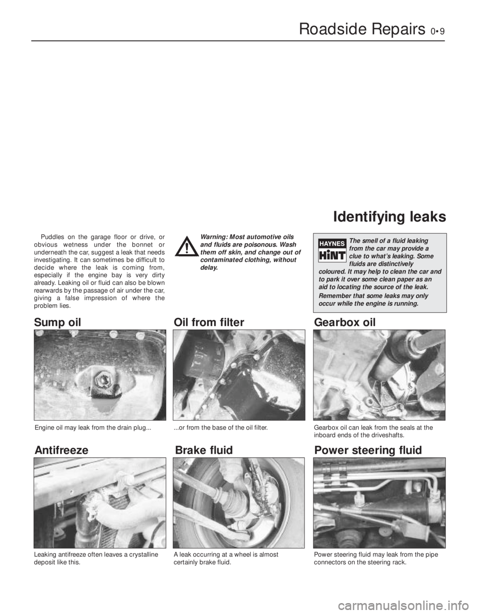
Puddles on the garage floor or drive, or
obvious wetness under the bonnet or
underneath the car, suggest a leak that needs
investigating. It can sometimes be difficult to
decide where the leak is coming from,
especially if the engine bay is very dirty
already. Leaking oil or fluid can also be blown
rearwards by the passage of air under the car,
giving a false impression of where the
problem lies.Warning: Most automotive oils
and fluids are poisonous. Wash
them off skin, and change out of
contaminated clothing, without
delay.
Identifying leaks
The smell of a fluid leaking
from the car may provide a
clue to what’s leaking. Some
fluids are distinctively
coloured. It may help to clean the car and
to park it over some clean paper as an
aid to locating the source of the leak.
Remember that some leaks may only
occur while the engine is running.
Sump oil Gearbox oil
Brake fluid
Power steering fluid
Oil from filter
Antifreeze
Engine oil may leak from the drain plug......or from the base of the oil filter.
Leaking antifreeze often leaves a crystalline
deposit like this.Gearbox oil can leak from the seals at the
inboard ends of the driveshafts.
A leak occurring at a wheel is almost
certainly brake fluid.Power steering fluid may leak from the pipe
connectors on the steering rack.
Page 27 of 303
24Screw in the big-end bolts and tighten to
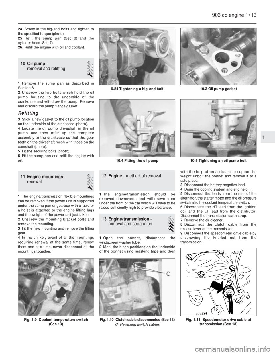
the specified torque (photo).
25Refit the sump pan (Sec 8) and the
cylinder head (Sec 7).
26Refill the engine with oil and coolant.
10 Oil pump-
removal and refitting
1
1Remove the sump pan as described in
Section 8.
2Unscrew the two bolts which hold the oil
pump housing to the underside of the
crankcase and withdraw the pump. Remove
and discard the pump flange gasket.
Refitting
3Stick a new gasket to the oil pump location
on the underside of the crankcase (photo).
4Locate the oil pump driveshaft in the oil
pump and then offer up the complete
assembly to the crankcase so that the gear
teeth on the driveshaft mesh with those on the
camshaft (photo).
5Fit the securing bolts (photo).
6Fit the sump pan and refill the engine with
oil.
11 Engine mountings-
renewal
1
1The engine/transmission flexible mountings
can be removed if the power unit is supported
under the sump pan or gearbox with a jack, or
a hoist is attached to the engine lifting lugs
and the weight of the power unit just taken.
2Unscrew the mounting bracket bolts and
remove the mounting.
3Fit the new mounting and remove the lifting
gear.
4In the unlikely event of all the mountings
requiring renewal at the same time, renew
them one at a time, never disconnect all the
mountings together.
12 Engine- method of removal
1The engine/transmission should be
removed downwards and withdrawn from
under the front of the car which will have to be
raised sufficiently high to provide clearance.
13 Engine/transmission-
removal and separation
3
1Open the bonnet, disconnect the
windscreen washer tube.
2Mark the hinge positions on the underside
of the bonnet using masking tape and thenwith the help of an assistant to support its
weight unbolt the bonnet and remove it to a
safe place.
3Disconnect the battery negative lead.
4Drain the cooling system and engine oil.
5Disconnect the leads from the rear of the
alternator, the starter motor and the oil pressure
switch also the coolant temperature switch.
6Disconnect the HT lead from the ignition
coil and the LT lead from the distributor.
Disconnect the transmission earth strap.
7Remove the air cleaner.
8Disconnect the clutch cable from the
release lever at the transmission.
9Disconnect the speedometer drive cable by
unscrewing the knurled nut from the
transmission.
903 cc engine 1•13
10.3 Oil pump gasket
10.4 Fitting the oil pump10.5 Tightening an oil pump bolt
9.24 Tightening a big-end bolt
Fig. 1.11 Speedometer drive cable at
transmission (Sec 13)Fig. 1.10 Clutch cable disconnected (Sec 13)
C Reversing switch cablesFig. 1.9 Coolant temperature switch
(Sec 13)
1
Page 41 of 303

2The big-end bearing shells can be renewed
without having to remove the cylinder head if
the caps are unbolted and the
piston/connecting rod pushed gently about
one inch up the bore (the crankpin being at its
lowest point). If these shells are worn,
however, the main bearing shells will almost
certainly be worn as well. In this case, the
engine should be removed for complete
overhaul including crankshaft removal.
3To remove the piston/connecting rods,
remove the cylinder head as described in
Section 29.
4Grip the oil pick-up pipe and twist or rock it
from its hole in the crankcase. It is an
interference fit in the hole.
5Unscrew the nuts from the big-end caps,
then remove the caps with their bearing
shells. The caps and their connecting rods are
numbered 1, 2, 3 and 4 from the timing cover
end of the engine. The numbers are adjacent
at the big-end cap joint and on the side of the
crankcase furthest from the auxiliary shaft.
6If the bearing shells are to be used again,
tape them to their respective big-end caps.
7Push each connecting rod/piston assembly
up the bore and out of the cylinder block.
There is one reservation; if a wear ridge has
developed at the top of the bores, remove this
by careful scraping before trying to remove
the piston/rod assemblies. The ridge will
otherwise prevent removal or break the piston
rings during the attempt.
8If the connecting rod bearing shells are to
be used again, tape the shells to their
respective rods.
9Dismantling the piston/connecting rod is
described in Section 18.
Refitting
10Fit the new shells into the connecting rod
and caps, ensuring the surfaces on which the
shells seat, are clean and dry.
11Check that the piston ring gaps are evenly
spaced at 120º intervals. Liberally oil the rings
and the cylinder bores.
12Fit a piston ring clamp to compress the
rings.
13Insert the piston/connecting rod into the
cylinder bore, checking that the rod assembly
is correct for that particular bore. The cap and
rod matching numbers must be furthest away
from the auxiliary shaft (Fig. 1.31).14Push the piston into the bore until the
piston ring clamp is against the cylinder block
and then tap the crown of the piston lightly to
push it out of the ring clamp and into the bore
(photo).
15Oil the crankshaft journal and fit the
big-end of the connecting rod to the journal.
Fit the big-end cap and nuts, checking that
the cap is the right way round (photo).
16Tighten the big-end nuts to the specified
torque. The correct torque is important as the
nuts have no locking arrangement. After
tightening each big-end, check the crankshaft
rotates smoothly (photo).
17Refit the oil pick-up pipe, the cylinder
head, oil pump and sump pan, all as
described earlier.
18Refill the engine with oil and coolant.
33 Engine mountings-
renewal
1
1Three engine/transmission flexible
mountings are used.
2To renew a mounting, support the weight of
the engine/transmission on a hoist or jack and
unbolt and remove the mounting.
3In the unlikely event of all three mountings
requiring renewal at the same time, only
disconnect them and renew them one at a
time.
34 Engine- method of removal
1The engine complete with transmission
should be removed by lowering it to the floor
and withdrawing it from under the front of the
car which will have been raised to provide
adequate clearance.
35 Engine/transmission-
removal and separation
3
1Open the bonnet, disconnect the
windscreen washer tube.
2Mark the hinge positions on the undersideof the bonnet and then with the help of an
assistant to support its weight unbolt and
remove the bonnet to a safe place.
3Disconnect the battery negative lead.
4Drain the cooling system and the engine
and transmission oils.
5Remove the air cleaner.
6From the rear of the alternator disconnect
the electrical leads.
7Disconnect the leads from the starter
motor, oil pressure and coolant temperature
switches, also the oil temperature switch.
8Disconnect the LT lead from the distributor
and the HT lead from the ignition coil.
9Disconnect the clutch cable from the
release lever at the transmission. Also
disconnect the speedometer drive cable
(knurled ring).
10Pull the leads from the reversing lamp
switch.
11Disconnect all coolant hoses from the
engine. Also disconnect the brake servo hose
from the intake manifold.
12Disconnect the choke and throttle
controls from the carburettor.
13Disconnect the inlet hose from the fuel
pump and plug the hose.
14Disconnect the fuel return hose from the
carburettor.
15Disconnect the coolant hoses from the
carburettor throttle block.
16Raise the front of the car and remove the
front roadwheels.
17Unscrew and remove the driveshaft to
hub nuts. These are very tight and a long
knuckle bar will be required when unscrewing
them. Have an assistant apply the brake pedal
hard to prevent the hub from turning.
18Working under the car, remove the inner
wing protective shields and then disconnect
the exhaust downpipe from the manifold.
19Disconnect the exhaust pipe sections by
removing the socket clamp just forward of the
rear axle beam. Remove the front section.
20Disconnect the forward ends of the
gearchange rods by prising their sockets from
the ballstuds.
21Unscrew the nuts on the steering tie-rod
end balljoints and then using a suitable
“splitter” tool, separate the balljoints from the
steering arms.
22Unbolt the front brake hose support clips
1116 cc and 1301 cc engine 1•27
32.16 Tightening a big-end cap nut32.15 Fitting a big-end cap32.14 Fitting piston into cylinder bore
1
Page 48 of 303

to the engine. Also reconnect the brake servo
hose to the intake manifold (photos).
22Reconnect the leads to the reversing lamp
switch. Reconnect the transmission earth lead
(photos).
23Reconnect the clutch cable and adjust as
described in Chapter 5.
24Reconnect the speedometer drive cable
to the transmission and tighten the knurled
retaining ring.
25Reconnect the low tension lead to the
distributor and the high tension lead to the
ignition coil.
26Reconnnect the electrical leads to thestarter motor, the oil pressure and
temperature switches and the coolant
temperature switch.
27Connect the leads to the alternator.
28Refit the air cleaner.
29Refill the cooling system. Refill the engine
with oil.
30Reconnect the battery.
31Refit the bonnet and connect the
windscreen washer tube.
32Fit the inner wing protective shields
(photo).
45 Engine- initial start-up after
major overhaul
4
1If new bearings and rings have been fitted,
it is likely that the engine will be stiff to turn so
make sure the battery is well charged.
2Switch on the ignition and check that
appropriate warning lights come on.
3Start up the engine. If it refuses to start,
refer to the “Fault Finding” Section in the
Reference section of this Manual.
4Watch the oil pressure warning light and
alternator charging indicator light. If there is
no charge or if the oil pressure warning light
does not go out after a second or two, havinghad time to fill the new oil filter, switch off and
recheck.
5If the warning lights go out, set the engine
to run on fast idle and check the engine for
leaks.
6Check the coolant level; it will probably go
down as air locks are filled.
7Keep the engine running at a fast idle and
bring it up to normal working temperature. As
the engine warms up, there will be some odd
smells and smoke from parts getting hot and
burning off oil deposits.
8When the engine running temperature has
been reached, adjust the idling speed, as
described in Chapter 3. Check and, if
necessary, adjust the ignition timing using a
stroboscope (see Chapter 4).
9Stop the engine and wait a few minutes;
check to see if there are any coolant or oil
leaks.
10Road test the car to check that the engine
is running with the correct smoothness and
power. If it does not, refer to “Fault finding” in
the Reference section of this Manual. Do not
race the engine. If new bearings and/or
pistons and rings have been fitted, it should
be treated as a new engine and run it at
reduced speed for at east 800 km (500 miles).
11After 800 km (500 miles) change the
engine oil and filter.
1•34 1116 cc and 1301 cc engine
44.32 Inner wing protective shield44.26B Coolant temperature switch44.26A Oil pressure warning switch
44.22B Transmission earth lead
44.22A Reversing lamp switch on
transmission44.21B Brake servo hose at manifold44.21A Heater hose at manifold
Page 54 of 303
towards the engine. Slip the belt off the
pulleys. If this is difficult, turn the crankshaft
pulley using a spanner on its retaining nut
while pressing the belt over the edge of the
pulley rim. Use this method to fit the new belt
after first having engaged it with the coolant
pump and alternator pulley grooves.
5Tension the belt as previously described.
6The tension of a new belt should be
checked and adjusted after the first few
hundred miles of running.
9 Coolant pump- removal,
overhaul and refitting
4
Note: The design of the pump differs between
the 903 cc and the other two engines, but the
removal, overhaul and refitting operations are
essentially similar.
1To gain access to the coolant pump, open
the bonnet and remove the air cleaner.
2Slacken the alternator pivot and adjustment
nuts, push the alternator in towards the
engine and slip the drivebelt from the coolant
pump pulley. Unplug and remove the
alternator.3Drain the cooling system as previously
described.
4Disconnect the hoses from the coolant
pump, also the metal coolant transfer pipe
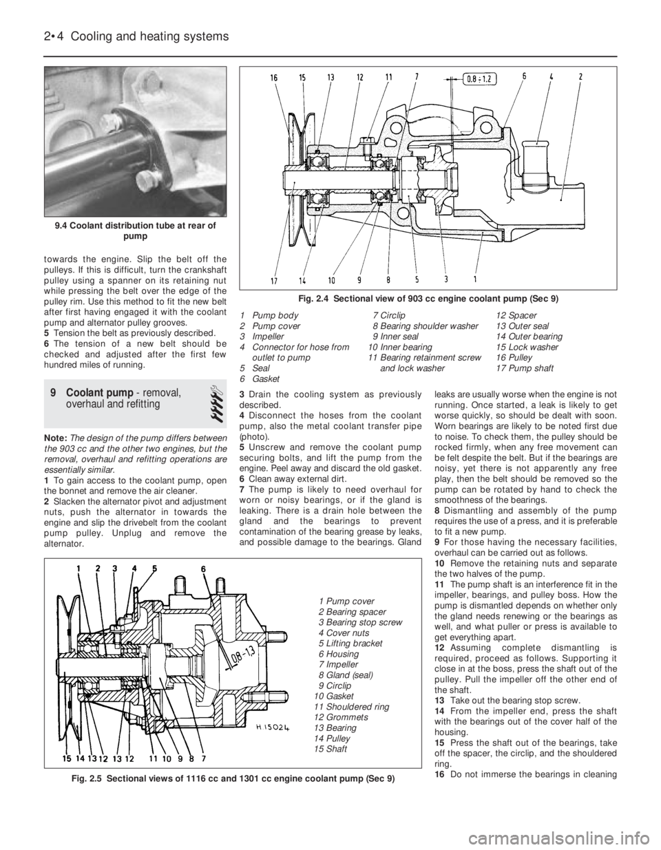
(photo).
5Unscrew and remove the coolant pump
securing bolts, and lift the pump from the
engine. Peel away and discard the old gasket.
6Clean away external dirt.
7The pump is likely to need overhaul for
worn or noisy bearings, or if the gland is
leaking. There is a drain hole between the
gland and the bearings to prevent
contamination of the bearing grease by leaks,
and possible damage to the bearings. Glandleaks are usually worse when the engine is not
running. Once started, a leak is likely to get
worse quickly, so should be dealt with soon.
Worn bearings are likely to be noted first due
to noise. To check them, the pulley should be
rocked firmly, when any free movement can
be felt despite the belt. But if the bearings are
noisy, yet there is not apparently any free
play, then the belt should be removed so the
pump can be rotated by hand to check the
smoothness of the bearings.
8Dismantling and assembly of the pump
requires the use of a press, and it is preferable
to fit a new pump.
9For those having the necessary facilities,
overhaul can be carried out as follows.
10Remove the retaining nuts and separate
the two halves of the pump.
11The pump shaft is an interference fit in the
impeller, bearings, and pulley boss. How the
pump is dismantled depends on whether only
the gland needs renewing or the bearings as
well, and what puller or press is available to
get everything apart.
12Assuming complete dismantling is
required, proceed as follows. Supporting it
close in at the boss, press the shaft out of the
pulley. Pull the impeller off the other end of
the shaft.
13Take out the bearing stop screw.
14From the impeller end, press the shaft
with the bearings out of the cover half of the
housing.
15Press the shaft out of the bearings, take
off the spacer, the circlip, and the shouldered
ring.
16Do not immerse the bearings in cleaning
2•4 Cooling and heating systems
1 Pump body
2 Pump cover
3 Impeller
4 Connector for hose from
outlet to pump
5 Seal
6 Gasket7 Circlip
8 Bearing shoulder washer
9 Inner seal
10 Inner bearing
11 Bearing retainment screw
and lock washer12 Spacer
13 Outer seal
14 Outer bearing
15 Lock washer
16 Pulley
17 Pump shaft
Fig. 2.5 Sectional views of 1116 cc and 1301 cc engine coolant pump (Sec 9)
Fig. 2.4 Sectional view of 903 cc engine coolant pump (Sec 9)
9.4 Coolant distribution tube at rear of
pump
1 Pump cover
2 Bearing spacer
3 Bearing stop screw
4 Cover nuts
5 Lifting bracket
6 Housing
7 Impeller
8 Gland (seal)
9 Circlip
10 Gasket
11 Shouldered ring
12 Grommets
13 Bearing
14 Pulley
15 Shaft
Page 95 of 303
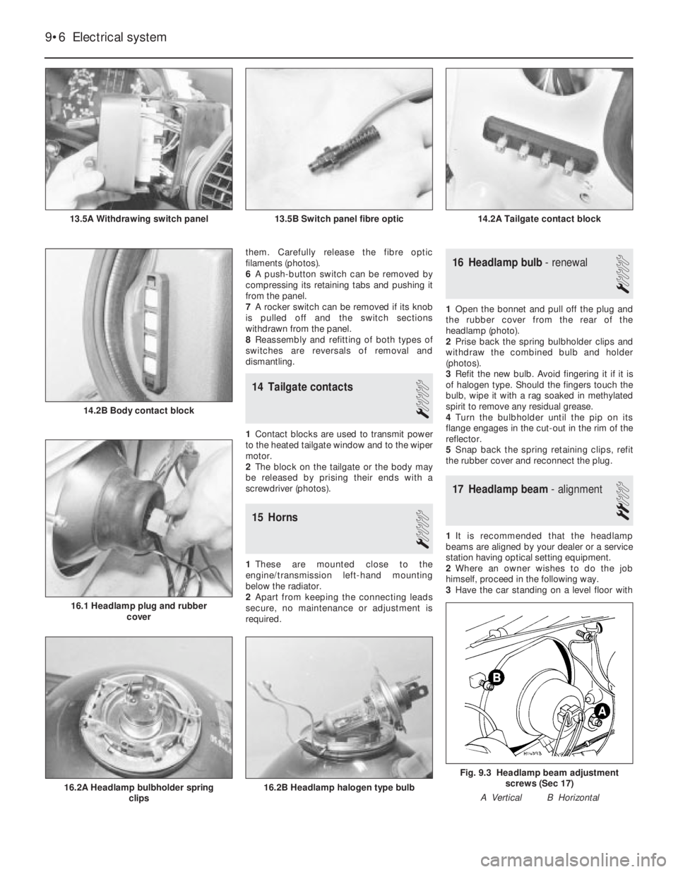
them. Carefully release the fibre optic
filaments (photos).
6A push-button switch can be removed by
compressing its retaining tabs and pushing it
from the panel.
7A rocker switch can be removed if its knob
is pulled off and the switch sections
withdrawn from the panel.
8Reassembly and refitting of both types of
switches are reversals of removal and
dismantling.
14 Tailgate contacts
1
1Contact blocks are used to transmit power
to the heated tailgate window and to the wiper
motor.
2The block on the tailgate or the body may
be released by prising their ends with a
screwdriver (photos).
15 Horns
1
1These are mounted close to the
engine/transmission left-hand mounting
below the radiator.
2Apart from keeping the connecting leads
secure, no maintenance or adjustment is
required.
16 Headlamp bulb- renewal
1
1Open the bonnet and pull off the plug and
the rubber cover from the rear of the
headlamp (photo).
2Prise back the spring bulbholder clips and
withdraw the combined bulb and holder
(photos).
3Refit the new bulb. Avoid fingering it if it is
of halogen type. Should the fingers touch the
bulb, wipe it with a rag soaked in methylated
spirit to remove any residual grease.
4Turn the bulbholder until the pip on its
flange engages in the cut-out in the rim of the
reflector.
5Snap back the spring retaining clips, refit
the rubber cover and reconnect the plug.
17 Headlamp beam- alignment
2
1It is recommended that the headlamp
beams are aligned by your dealer or a service
station having optical setting equipment.
2Where an owner wishes to do the job
himself, proceed in the following way.
3Have the car standing on a level floor with
9•6 Electrical system
Fig. 9.3 Headlamp beam adjustment
screws (Sec 17)
A Vertical B Horizontal
16.2B Headlamp halogen type bulb16.2A Headlamp bulbholder spring
clips
14.2B Body contact block
16.1 Headlamp plug and rubber
cover
14.2A Tailgate contact block13.5B Switch panel fibre optic13.5A Withdrawing switch panel
Page 96 of 303

the tyres correctly inflated and square to a
wall, at a distance of 10.0 m (32.8 ft) from it.
4Mark the wall to correspond with the
centres of the headlamps.
5Switch to dipped beams when the brightest
parts of the light pattern should be below the
marks on the wall by an amount equal to one
tenth of the distance between the floor and
the mark on the wall.
6Adjust the beams as necessary by turning
the adjuster screws (A) vertical or (B) hori-
zontal, which are located at the rear of the
headlamp.
18 Headlamp-
removal and refitting
1
1Open the bonnet and extract the two
headlamp mounting screws from the top rail
(photo).
2Pull the headlamp unit forward off its
ballstud and then disconnect the wiring plug
(photo).
3Refitting is a reversal of removal.
19 Exterior lamps-
bulb renewal
1
Front parking lamp
1The bulbholder is located in the headlamp
reflector. 2Open the bonnet, push and twist the
bulbholder from its location (photo).
3The wedge base type bulb is simply pulled
from its holder.
Front direction indicator lamp
4Extract the screws and remove the lens
(photo).
5Depress and twist the bayonet fitting type
bulb from its holder.
Side repeater lamp
6This bulb may be renewed in one of two
ways. Either partially remove the underwing
protective shield and reach up under the front
wing and pull the holder out of the lamp body
or depress the lamp retaining tab and
withdraw the lamp from outside the wing. The
tab is very brittle (photo). 7Remove the bulb from the holder.
Rear lamp cluster
8Open the tailgate.
9Gently prise up the clips on the top surface of
the lens. Pull the upper part of the lens outwards
and release it from the lower fixings (photo).
10The individual lamp bulbs may be
renewed, all of them being of bayonet fitting
type (photo).
Rear number plate lamp
11Insert a screwdriver blade in the lens slot
and prise it from the bulb holder. Withdraw
the bulb.
12If preferred, the complete lamp may be
removed from the bumper by reaching up
under the bumper and squeezing the lamp
retaining tabs (photo).
Electrical system 9•7
19.2 Front parking lamp bulb18.2 Withdrawing headlamp18.1 Headlamp upper fixing screw
19.12 Rear number plate lamp withdrawn
19.10 Rear lamp bulbs
19.6 Side repeater lamp19.4 Front direction indicator lamp lens
and bulb
19.9 Rear lamp lens upper clip
9
A Direction indicator
B ReversingC Stop E Fog
D Tail
Page 98 of 303
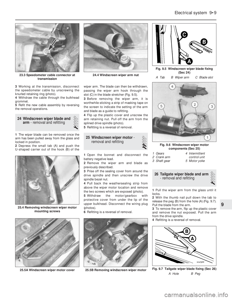
3Working at the transmission, disconnect
the speedometer cable by unscrewing the
knurled retaining ring (photo).
4Withdraw the cable through the bulkhead
grommet.
5Refit the new cable assembly by reversing
the removal operations.
24 Windscreen wiper blade and
arm- removal and refitting
1
1The wiper blade can be removed once the
arm has been pulled away from the glass and
locked in position.
2Depress the small tab (A) and push the
U-shaped carrier out of the hook (B) of thewiper arm. The blade can then be withdrawn,
passing the wiper arm hook through the
slot (C) in the blade stretcher (Fig. 9.5).
3Before removing the wiper arm, it is
worthwhile sticking a strip of masking tape on
the screen to indicate the setting of the arm
and blade as a guide to refitting.
4Flip up the plastic cover and unscrew the
arm retaining nut. Pull off the arm from the
splined drive spindle (photo).
5Refitting is a reversal of removal.25 Windscreen wiper motor-
removal and refitting
2
1Open the bonnet and disconnect the
battery negative lead.
2Remove the wiper arm and blade as
previously described.
3Prise off the sealing cover from around the
drive spindle and then unscrew the drive
spindle bezel nut.
4Pull back the weathersealing strip from
above the wiper motor location and remove
the two screws which are exposed (photo).
5Withdraw the motor/gearbox with
protective cover from under the lip of the
upper bulkhead. Disconnect the wiring plug
(photos).
6Refitting is a reversal of removal.
26 Tailgate wiper blade and arm
- removal and refitting
1
1Pull the wiper arm from the glass until it
locks.
2With the thumb nail pull down the tab to
release the peg (B) from the hole (A) (Fig. 9.7).
Pull the blade from the arm.
3To remove the arm, flip up the plastic cover
and remove the nut exposed. Pull the arm
from the drive spindle.
4Refitting is a reversal of removal.
Electrical system 9•9
Fig. 9.5 Windscreen wiper blade fixing
(Sec 24)
A Tab B Wiper arm C Blade slot
24.4 Windscreen wiper arm nut23.3 Speedometer cable connector at
transmission
Fig. 9.7 Tailgate wiper blade fixing (Sec 26)
A Hole B Peg25.5B Removing windscreen wiper motor25.5A Windscreen wiper motor cover
25.4 Removing windscreen wiper motor
mounting screws
Fig. 9.6 Windscreen wiper motor
components (Sec 25)
1 Gears 4 Intermittent
2 Crank arm control unit
3 Shaft gear 5 Motor yoke
9