Page 145 of 252
140
CHAPTER
ELEVEN
@
sleeve
into
gear
at
the
same
tune
This
will
lock
the
mam
shaft
Release
the
main
shaft
nut
12
Withdraw
the
counter
shaft
and
remove
the
counter
gear
with
the
two
needle
roller
bearings
and
spacers
13
Refer
to
Figure
27
Release
reverse
idler
gear
snap
ring
Remove
reverse
idler
gears
and
shaft
@
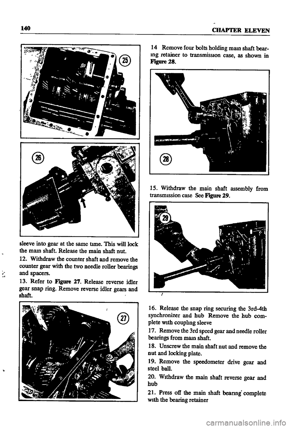
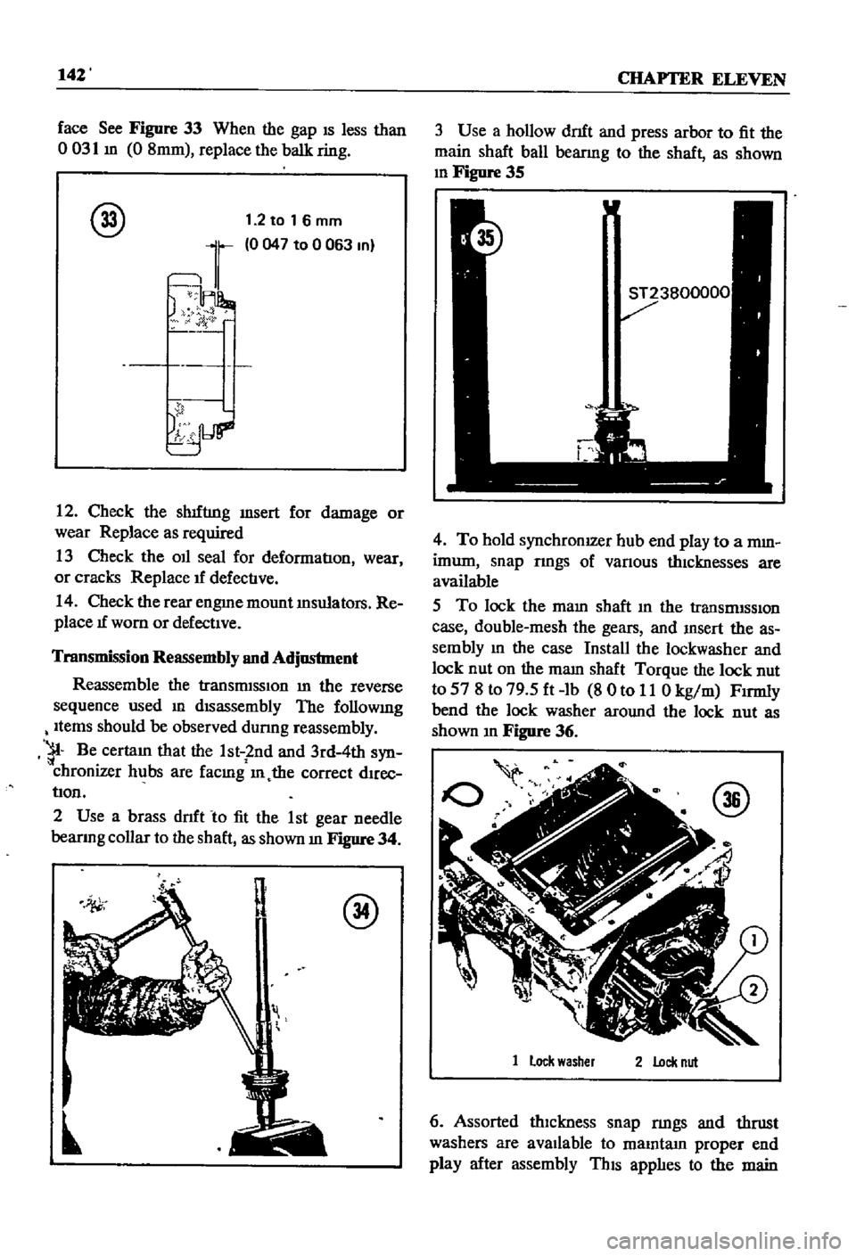
14
Remove
four
bolts
holding
maIn
shaft
bear
Ing
retainer
to
transmissIOn
case
as
shown
in
Figure
28
@
15
Withdraw
the
main
shaft
assembly
from
transmIssion
case
See
Figure
29
16
Release
the
snap
ring
securing
the
3rd
4th
synchronizer
and
hub
Remove
the
hub
com
plete
With
couplIng
sleeve
17
Remove
the
300
speed
gear
and
needle
roller
bearings
from
maIn
shaft
18
Unscrew
the
main
shaft
nut
and
remove
the
nut
and
locking
plate
19
Remove
the
speedometer
drive
gear
and
steel
ball
20
WIthdraw
the
main
shaft
reverse
gear
and
hub
21
Press
off
the
main
shaft
bearmg
complete
With
the
bearing
retainer
Page 146 of 252

CLUTCH
TRANSMISSION
AND
DRlVESHAFI
141
22
Remove
the
thrust
washer
and
mam
shaft
1st
speed
gear
complete
With
needle
roller
bear
mg
Be
careful
not
to
lose
the
small
steel
ball
which
locates
the
thrust
washer
Remove
main
shaft
1st
gear
bushmg
23
Remove
the
mam
shaft
2nd
speed
gear
and
needle
roller
bearmg
24
To
dISassemble
synchronizer
assembly
re
move
sprmgs
from
both
ends
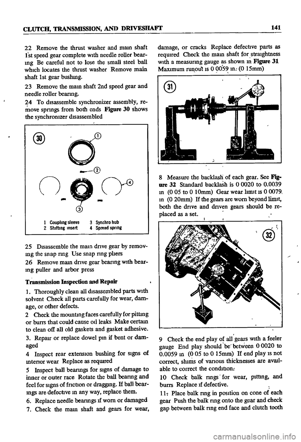
Figure
30
shows
the
synchronIZer
dIsassembled
@
d
@
n
9
cr
1
Coupling
slee
e
3
Synchro
hub
2
Shlftmg
msert
4
Spread
spnng
25
DIsassemble
the
mam
dnve
gear
by
remov
mg
the
snap
nng
Use
snap
nng
phers
26
Remove
mam
dnve
gear
bearmg
With
bear
Ing
puller
and
arbor
press
Transmission
Inspection
and
Repair
1
Thoroughly
clean
all
dtsassembled
parts
With
solvent
Check
all
parts
carefully
for
wear
dam
age
or
other
defects
2
Check
the
mountIng
faces
carefully
for
pittIng
or
burrs
that
could
cause
011
leaks
Make
certatn
to
clean
off
all
old
gaskets
and
gasket
adhesive
3
RepaIr
or
replace
dowel
pm
if
bent
or
dam
aged
4
Inspect
rear
extensIon
bushing
for
SIgnS
of
mtenor
wear
Replace
as
reqUIred
5
Inspect
ball
bearmgs
for
SIgnS
of
damage
to
inner
or
outer
race
Rotate
the
ball
bearmg
and
feel
for
SIgnS
of
fnctIon
or
draggmg
If
ball
bear
mgs
are
defectIve
In
any
way
replace
them
6
Replace
needle
bearIngs
1f
wom
or
damaged
7
Check
the
mam
shaft
and
gears
for
wear
damage
or
cracks
Replace
defectIve
parts
as
required
Check
the
maIn
shaft
for
straIghtness
WIth
a
measurmg
gauge
as
shown
m
Figure
31
MaxImum
runpulls
0
0059
m
0
15mm
@
8
Measure
the
backlasH
of
each
gear
See
Fig
nre
32
Standard
backlash
is
0
0020
to
0
0039
In
0
05
to
0
10mm
Gear
wear
hrmt
IS
0
0079
In
0
20mm
If
the
gears
are
worn
beyond
limtt
both
the
dnve
and
dnven
gears
should
be
re
placed
as
a
set
@
9
Check
the
end
play
of
all
gears
WIth
a
feeler
gauge
End
play
should
be
between
0
0020
to
0
0059
m
005
to
0
15mm
If
end
play
IS
not
correct
Sh1nIS
of
vanous
thicknesses
are
avail
able
to
correct
the
condItIon
10
Check
balk
nngs
for
wear
plttmg
and
burrs
Replace
1f
defective
11
Place
balk
rmg
in
pOSItion
on
cone
of
each
gear
Push
the
balk
rmg
onto
the
gear
and
check
gap
between
balk
nng
end
face
and
clutch
tooth
Page 147 of 252

142
CHAPTER
ELEVEN
face
See
Figure
33
When
the
gap
IS
less
than
o
031
m
0
8mm
replace
the
balk
ring
@
1
2
to
1
6
mm
0047
to
0
063
In
12
Check
the
sh1fnng
msert
for
damage
or
wear
Replace
as
required
13
Check
the
OIl
seal
for
deformatIon
wear
or
cracks
Replace
1f
defectIve
14
Check
the
rear
engme
mount
Insulators
Re
place
1f
worn
or
defectIve
Transmission
Reassembly
and
Adjustment
Reassemble
the
transmISSIon
In
the
reverse
sequence
used
ill
dIsassembly
The
followmg
Items
should
be
observed
dunng
reassembly
1
Be
certaIn
that
the
1st
2nd
and
3rd
4th
syn
chronizer
hubs
are
facmg
ill
the
correct
dIrec
tIon
2
Use
a
brass
dnft
to
fit
the
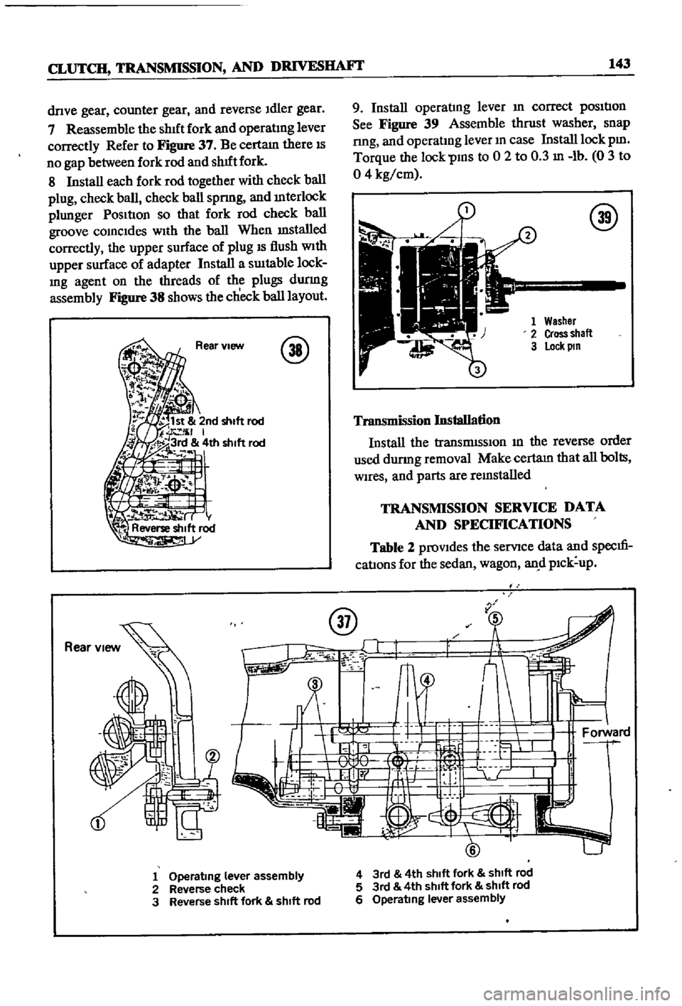
1
st
gear
needle
bearlOg
collar
to
the
shaft
as
shown
In
Figure
34
il
@
3
Use
a
hollow
dnft
and
press
arbor
to
fit
the
main
shaft
ball
bearmg
to
the
shaft
as
shown
10
Figure
35
4
To
hold
synchronIZer
hub
end
play
to
a
mm
imum
snap
rmgs
of
vanous
thIcknesses
are
available
5
To
lock
the
malO
shaft
m
the
transrmSSlOn
case
double
mesh
the
gears
and
msert
the
as
sembly
10
the
case
Install
the
lockwasher
and
lock
nut
on
the
mam
shaft
Torque
the
lock
nut
to
57
8
to
79
5
ft
lb
8
0
to
11
0
kg
m
Fumly
bend
the
lock
washer
around
the
lock
nut
as
shown
In
Figure
36
1
lock
washer
2
Lock
nut
6
Assorted
thIckness
snap
nngs
and
thrust
washers
are
avallable
to
malOtam
proper
end
play
after
assembly
ThIS
applIes
to
the
main
Page 148 of 252

CLUTCH
TRANSMISSION
AND
DRlVESHAFI
143
dnve
gear
counter
gear
and
reverse
Idler
gear
7
Reassemble
the
shIft
fork
and
operatIng
lever
correctly
Refer
to
Figure
37
Be
certam
there
IS
no
gap
between
fork
rod
and
shUt
fork
8
Install
each
fork
rod
together
with
check
ball
plug
check
ball
check
ball
spnng
and
mterlock
plunger
PosItIon
so
that
fork
rod
check
ball
groove
comcldes
wIth
the
ball
When
mstalled
correctly
the
upper
surface
of
plug
IS
flush
With
upper
surface
of
adapter
Install
a
sUItable
lock
Ing
agent
on
the
threads
of
the
plugs
durmg
assembly
Figure
38
shows
the
check
ball
layout
@
9
Install
operatIng
lever
In
correct
pOSItIon
See
Figure
39
Assemble
thrust
washer
snap
nng
and
operatlDg
lever
m
case
Install
lock
pm
Torque
the
lock
PIDS
to
0
2
to
0
3
In
lb
0
3
to
04
kg
cm
@
Washer
Cross
shall
lock
pm
Transmission
Installation
Install
the
tranSmISSIon
m
the
reverse
order
used
durmg
removal
Make
certam
that
all
bolts
Wires
and
parts
are
remstalled
TRANSMISSION
SERVICE
DATA
AND
SPECIFICATIONS
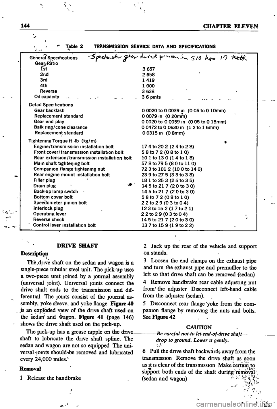
Table
2
proVIdes
the
servlce
data
and
specm
catIons
for
the
sedan
wagon
an
d
pIck
up
u
1
Operating
lever
assembly
2
Reverse
check
3
Reverse
shift
fork
shift
rod
4
3rd
4th
shift
fork
shift
rod
5
3rd
4th
shIft
fork
shift
rod
6
Operating
lever
assembly
Page 149 of 252

144
CHAPTER
ELEVEN
TAANSMISSlON
SERVICE
DATA
AND
SPECIRCATIONS
Table
2
r
General
SpecificatIOns
Gear
Ratlo
1st
2nd
3rd
4th
Reverse
011
capacity
Detail
SpeCIfications
Gear
backlash
Replacement
standard
Gear
end
play
Balk
ring
cone
clearance
Replacement
standard
5
tl
viV
t
O
5
0
If
3657
2558
1419
1000
3638
3
6
pints
Tightening
Torque
ft
Ib
kg
m
Engine
transmission
installation
bolt
Front
cover
transmission
installation
bolt
Rear
extensIon
transmIssion
installation
bolt
Main
shaft
tlghtel
lng
bolt
Companion
flange
tightening
nut
Rear
engine
mount
installation
bolt
Filler
plug
Drain
plug
Back
up
lamp
sWItch
Bottom
cover
bolt
Speedometer
pinion
bolt
Interlock
plug
Operating
lever
Reverse
check
Control
lever
installatIOn
bolt
00020
to
0
0039
In
005
to
0
10mm
o
0079
In
0
20mm
o
0020
to
0
0059
In
0
05
to
0
15mm
00472
to
0
0630
In
1
2
to
1
6mm
00315
In
08mm
174
to
20
2
24
to
2
8
5
8
to
7
2
0
8
to
1
0
10
1
to
130
1
4
to
1
8
57
8t079
5
80to
11
0
72
3
to
101
2
100
to
140
239
to
27
5
3
3
to
38
18
1
to
25
3
25
to
3
5
14
5
to
21
7
20
to
3
0
14
5
to
21
7
2
0
to
3
0
5
8
to
7
2
0
8
to
1
0
2
2
to
2
9
03
to
0
4
123
to
15
2
1
7
to
2
1
22
to
2
9
0
3
to
0
4
14
5
to
21
7
20
to
3
0
13
7
to
15
9
1
9
to
2
2
DRIVE
SHAFf
Descripti
ll
TIie
dnve
shaft
on
the
sedan
and
wagon
is
a
smgle
plece
tubular
steel
unit
The
pick
up
uses
a
two
pIece
umt
Joined
by
a
Journal
assembly
unIversal
Joint
UnIversal
Jomts
connect
the
drive
shaft
ends
to
the
transmissIOn
and
d1f
ferentIal
The
Jomts
consist
of
the
Journal
as
sembly
yoke
sleeve
and
yoke
flange
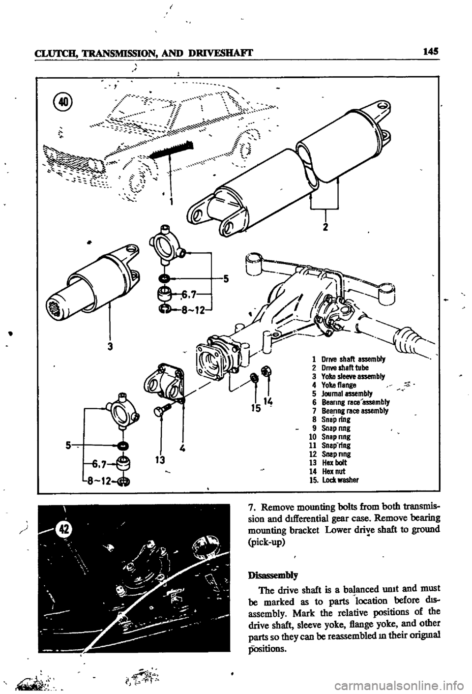
Figure
40
is
an
explOded
VIew
of
the
dnve
shaft
used
on
the
sedan
and
agon
Figure
41
page
146
shows
the
dnve
shaft
used
on
the
pIck
up
The
pIck
up
has
a
grease
mpple
on
the
dnve
shaft
to
lubncate
the
dnve
shaft
spline
The
sedan
and
wagon
are
not
so
equipped
The
uni
versal
Jomts
shouldebe
removed
and
lubncated
every
24
000
rmles
Removal
1
Release
the
handbrake
j
2
Jack
up
the
rear
of
the
vehIcle
and
support
on
stands
3
Loosen
the
end
clamps
on
the
exhaust
pipe
and
turn
the
exhaust
pIpe
and
premuffier
to
the
left
so
that
dnve
shaft
can
be
removed
sedan
4
Remove
handbrake
rear
cable
adjustIng
nut
from
the
adjuster
DIsconnect
left
hand
cable
from
the
adjuster
sedan
5
DIsconnect
rear
flange
yoke
from
the
com
panIon
flange
by
removmg
the
nuts
and
bolts
See
Figure
42
CAUTION
Be
careful
not
to
let
end
of
dnve
shaft
drop
to
ground
Lower
It
gently
6
Pull
the
dnve
shaft
backwards
away
from
the
transmISSIon
Remove
the
dnve
shaft
as
soon
as
It
IS
clear
of
the
transmISSIon
Make
cert
n
to
support
both
ends
of
the
shaft
duriftgi
mb
sedan
and
wagon
v
4
1tr
l
t
t
Page 150 of 252
CLUTCH
TRANSMISSION
AND
DRIVESIIAFT
145
r
@
l
S
St
P
t
ii
t
1
1
1
0
8
12
3
5
8
12
13
i
f
p
1
2
5
7
Remove
mounting
bolts
from
both
transmis
sion
and
dllIerential
gear
case
Remove
bearing
mounting
bracket
Lower
drive
shaft
to
ground
pick
up
J
iw
sembly
The
drive
shaft
is
a
balanced
unIt
and
must
be
marked
as
to
parts
location
before
dIS
assembly
Mark
the
relative
positions
of
the
drive
shaft
sleeve
yoke
flange
yoke
and
other
parts
so
they
can
be
reassembled
m
their
origmal
positions
Page 151 of 252

146
CHAPTER
ELEVEN
o
i
fij@
0
@
7
B@
I
l
I
L
J
1
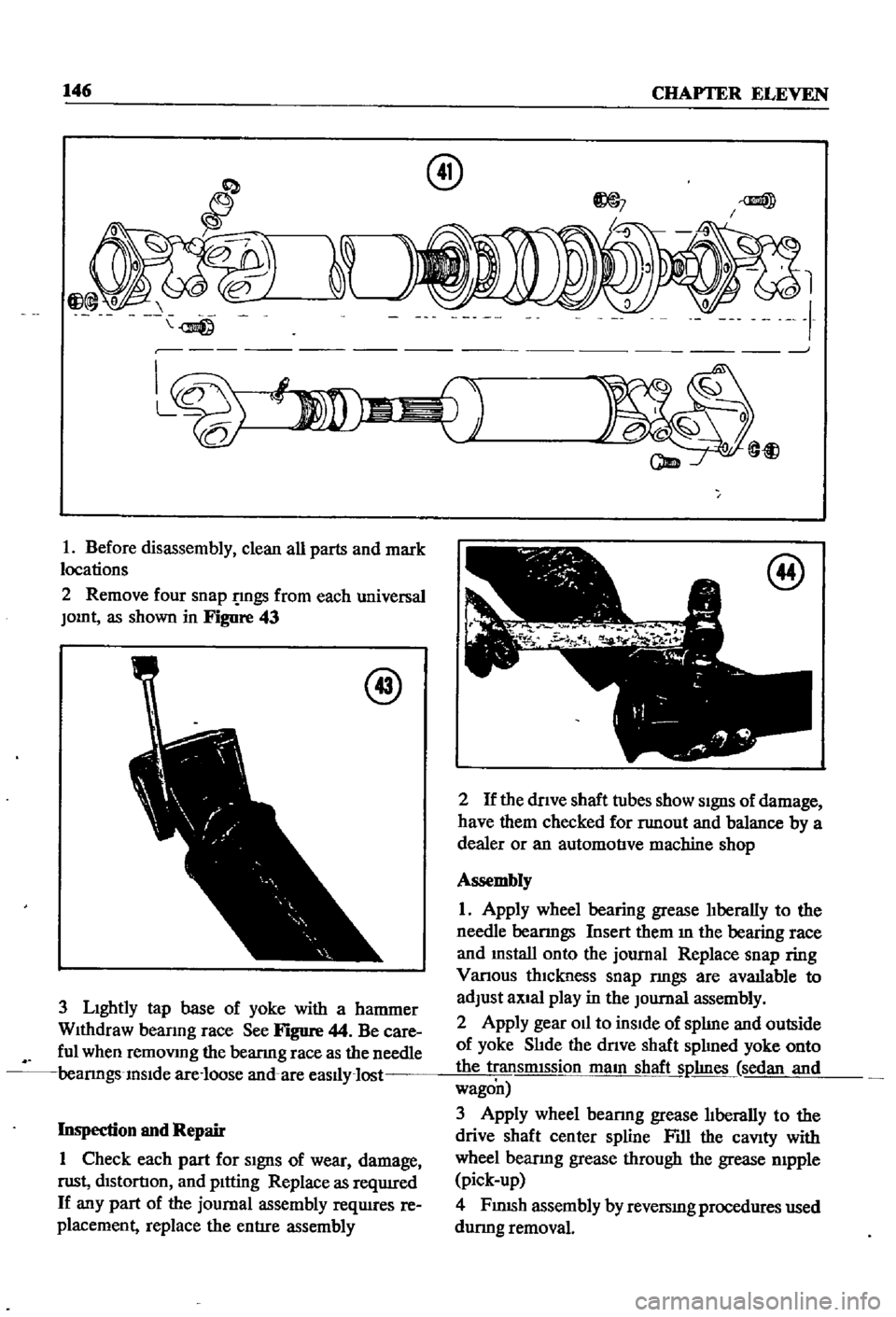
Before
disassembly
clean
all
parts
and
mark
locations
2
Remove
four
snap
gs
from
each
universal
JOInt
as
shown
in
Figure
43
@
3
LIghtly
tap
base
of
yoke
with
a
hammer
WIthdraw
beanng
race
See
Figure
44
Be
care
ful
when
remoVIng
the
bearmg
race
as
the
needle
bearmgs
InSIde
are
loose
and
are
easlly
lost
Inspection
and
Repair
1
Check
each
part
for
SIgnS
of
wear
damage
nlSt
dIStortIOn
and
pItting
Replace
as
reqUIred
If
any
part
of
the
journal
assembly
reqUIres
re
placement
replace
the
entIre
assembly
am
@
t
@
2
If
the
dnve
shaft
tubes
show
SIgnS
of
damage
have
them
checked
for
nmout
and
balance
by
a
dealer
or
an
automotIve
machine
shop
Assembly
1
Apply
wheel
bearing
grease
lIberally
to
the
needle
bearmgs
Insert
them
m
the
bearing
face
and
mstall
onto
the
journal
Replace
snap
ring
Vanous
thIckness
snap
nngs
are
avatlable
to
adjust
aXIal
play
in
the
Journal
assembly
2
Apply
gear
Oil
to
inSIde
of
splIne
and
outside
of
yoke
SlIde
the
dnve
shaft
splIned
yoke
onto
the
transmIssion
maIn
shaft
Sl1hnes
sedan
and
wagon
3
Apply
wheel
bearmg
grease
lIberally
to
the
drive
shaft
center
spline
Fill
the
caVIty
with
wheel
bearmg
grease
through
the
grease
mpple
pick
up
4
FJ
nlSh
assembly
by
reversIng
procedures
used
durmg
removal
Page 152 of 252

CLUTCH
TRANSMISSION
AND
DRIVESHAFI
147
SERVICE
DATA
AND
SPECIFICATIONS
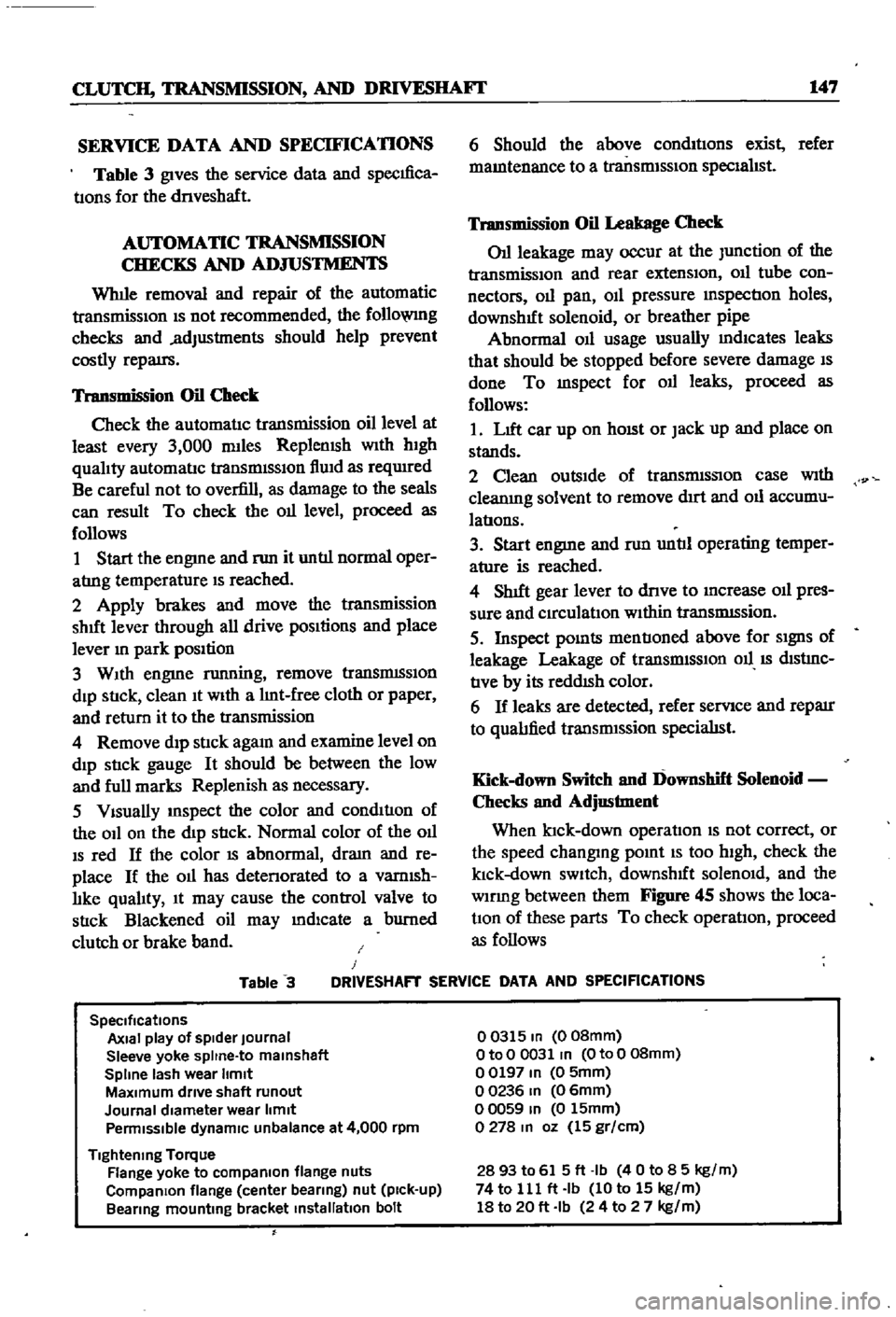
Table
3
gives
the
service
data
and
specIfica
tIons
for
the
dnveshaft
AUTOMATIC
TRANSMISSION
CHECKS
AND
ADJUSTMENTS
Whlle
removal
and
repair
of
the
automatic
transmisSIOn
IS
not
recommended
the
follo
VlIlg
checks
and
adjustments
should
help
prevent
costly
repatrs
Transmission
Oil
Check
Check
the
automatIc
transmission
oil
level
at
least
every
3
000
mlles
Replemsh
With
hIgh
qualIty
automatIc
transmISSIon
flUId
as
reqUIred
Be
careful
not
to
overfill
as
damage
to
the
seals
can
result
To
check
the
011
level
proceed
as
follows
1
Start
the
engme
and
nm
it
untIl
normal
oper
atrng
temperature
IS
reached
2
Apply
brakes
and
move
the
transmission
shut
lever
through
all
drive
pOSItions
and
place
lever
In
park
position
3
WIth
engme
running
remove
tranSmISSIon
dIp
StIck
clean
It
WIth
a
lInt
free
cloth
or
paper
and
return
it
to
the
transmission
4
Remove
dIp
stIck
agam
and
examine
level
on
dIp
stIck
gauge
It
should
be
between
the
low
and
full
marks
Replenish
as
necessary
5
VIsually
InSpect
the
color
and
condItIon
of
the
OIl
on
the
dIp
stIck
Normal
color
of
the
OIl
IS
red
If
the
color
IS
abnormal
dram
and
re
place
If
the
011
has
detenorated
to
a
vamlsh
lIke
qualIty
It
may
cause
the
control
valve
to
stIck
Blackened
oil
may
mdlcate
a
burned
clutch
or
brake
band
6
Should
the
above
condItIons
exist
refer
mamtenance
to
a
transmISSIon
specIalIst
Transmission
Oil
Leakage
Check
011
leakage
may
occur
at
the
Junction
of
the
transmissIon
and
rear
extensIon
011
tube
con
nectors
011
pan
OIl
pressure
mspectIon
holes
downshIft
solenoid
or
breather
pipe
Abnormal
OIl
usage
usually
mdlcates
leaks
that
should
be
stopped
before
severe
damage
IS
done
To
mspect
for
011
leaks
proceed
as
follows
1
LIft
car
up
on
hOISt
or
Jack
up
and
place
on
stands
2
Clean
outsIde
of
transmISSIon
case
With
cleanIng
solvent
to
remove
dIrt
and
011
accumu
latIons
3
Start
engme
and
nm
untIl
operating
temper
ature
is
reached
4
ShIft
gear
lever
to
dnve
to
Increase
011
pres
sure
and
CIrculatIon
WIthin
tranSmISsion
5
Inspect
pOInts
mentIoned
above
for
SIgnS
of
leakage
Leakage
of
transrmSSIOn
011
IS
dIStrnC
tIve
by
its
reddISh
color
6
If
leaks
are
detected
refer
servIce
and
reparr
to
qualIfied
transrmssion
specialISt
Kick
down
Switch
and
Downshift
Solenoid
Checks
and
Adjustment
When
ktck
down
operatIon
IS
not
correct
or
the
speed
changmg
pomt
IS
too
high
check
the
klck
down
SWItch
downshIft
solenOId
and
the
wlDng
between
them
Figure
45
shows
the
loca
tIOn
of
these
parts
To
check
operatIon
proceed
as
follows
Table
3
J
DRIVESHAFT
SERVICE
DATA
AND
SPECIFICATIONS
SpeCifications
Axial
play
of
spider
Journal
Sleeve
yoke
spltne
to
malnshaft
Spline
lash
wear
Itmlt
MaXimum
drive
shaft
runout
Journal
diameter
wear
limit
Penmlsslble
dynamiC
unbalance
at
4
000
rpm
Tightening
Torque
Flange
yoke
to
compaRlon
flange
nuts
CompaRlon
flange
center
bearing
nut
pick
up
Bearing
mounting
bracket
installation
bolt
00315
In
008mm
OtoO
0031
In
OtoO
08mm
00197
In
0
5mm
00236
In
06mm
00059
In
0
15mm
0278
In
oz
15
gr
cm
2893
to
615ft
Ib
40
to
8
5
kg
m
74
to
111
ft
Ib
10
to
15
kg
m
18
to
20
ft
Ib
24
to
2
7
kg
m