1968 DATSUN 510 seat adjustment
[x] Cancel search: seat adjustmentPage 5 of 252
CHAPTER
TWELVE
DIFFERENTIAL
REAR
AXLE
AND
REAR
SUSPENSION
149
DIfferentIal
Rear
axle
and
suspension
Codspnng
Shock
absorber
Rear
suspensIOn
arm
Rear
axle
shaft
Wheel
beanngs
Seals
Rear
spnng
Axle
case
SpecificatIons
CHAPTER
THIRTEEN
FRONT
AXLE
FRONT
SUSPENSION
AND
STEERING
168
Wheel
hub
and
bearmg
StabilIzer
TenSion
rod
Spnng
and
strut
assembly
Transverse
lInk
Lower
ball
Jomt
Front
suspension
adjustment
Wheel
alignment
Posture
adJustment
Steenng
system
SpeCificatIons
CHAPTER
FOURTEEN
BRAKES
187
Brake
pedal
Master
cylInder
Front
diSC
brakes
Rear
brakes
Front
drum
brakes
Wheel
cylInders
Brake
system
bleedIng
Handbrake
Service
data
and
speCificatIons
CHAPTER
FIFTEEN
BODY
ELECTRICAL
SYSTEM
Wmng
SWitches
and
fuses
Instrument
meters
and
panels
Heater
205
Wmdshleld
wipers
Wmdslueld
washers
Headlamps
WIrIng
diagrams
CHAPTER
SIXTEEN
BODY
223
Front
body
trIm
Bumpers
Hood
lock
control
Doors
Door
locks
and
regulators
Trunk
lId
and
rear
bumper
Seats
Tad
gate
INDEX
235
I
Page 30 of 252

ENGINE
AND
IGNITION
TUNE
UP
4
25
block
the
throttle
and
choke
m
the
WIde
open
position
3
Remove
all
four
spark
plugs
4
Sequentially
press
a
compressIOn
test
gauge
mto
each
of
the
spark
plug
holes
and
crank
the
engme
for
at
least
four
strokes
Record
the
com
pressIOn
readmg
for
each
cylmder
Standard
compressIOn
readmg
IS
171
Ibs
m
12
0
kg
cm
Mmlmum
acceptable
readmg
IS
159
lbs
m
2
11
5
kg
cm
5
No
readmg
should
be
less
than
80
of
the
highest
cylmder
reading
ExceSSive
vanatiC
ns
between
cylmders
accompanied
by
low
speed
mlssmg
of
the
cyhnder
or
cylmders
that
read
low
usually
mdlcates
a
valve
not
properly
seat
mg
or
a
broken
piston
ring
Low
pressures
even
though
uniform
may
mdicate
worn
nngs
ThIS
IS
especlall
true
1f
ex
cessive
011
cQIlsumptlon
has
been
noticed
If
one
or
more
cylmders
read
low
or
uneven
inject
about
a
tablespoon
of
engine
ail
on
top
of
the
piston
of
that
cylinder
and
crank
the
engine
several
tlmes
noting
the
compressIOn
reading
If
compressIOn
has
nsen
the
piston
nngs
or
cylmders
are
worn
and
should
befserviced
If
compressIOn
has
not
unproved
after
addmg
oil
the
valves
are
Stlcking
or
are
not
seating
prop
erly
If
two
adjacent
cylmders
have
low
compres
sion
and
mjectmg
01
9es
not
increas
the
read
mg
the
head
gasket
between
the
cylmders
IS
probably
leaking
VALVE
CLEARANCE
ADJUSTMENT
Valve
adjustment
should
be
done
in
two
steps
first
With
the
engme
cold
and
then
at
operatmg
temperature
Refer
to
Figure
6
and
proceed
as
follows
1
Remove
arr
liter
2
Remove
rocker
arm
cover
Take
care
not
to
damage
the
gasket
3
Remove
the
spark
plugs
and
rotate
the
en
gine
unt1l
number
1
cylinder
IS
at
top
dead
center
o
l
the
compressIOn
stroke
This
can
be
de
tepnmed
w
hen
the
top
dead
center
mark
on
the
crankshaft
pulley
is
m
alignment
With
the
statIOnary
pomter
and
both
valves
for
number
1
cylmder
are
closed
I
4
Counting
from
the
front
of
the
engme
ad
Just
valves
1
2
3
and
5
as
follows
Loosen
the
pivot
lockmg
nut
and
turn
the
pivot
screw
unt1l
clearance
between
the
pivot
screw
and
the
rock
er
ann
IS
0
0079
m
0
200mm
for
the
mtake
valves
and
0
0098
in
0
25mm
for
the
exhaust
valves
Check
clearances
With
a
feeler
gauge
as
shawn
When
correct
tlghten
the
pivot
locking
nut
l
1
5
Rotate
the
crankshaft
unt1l
the
number
4
pISton
IS
at
top
dead
center
an
the
compressIOn
stroke
This
IS
one
complete
revolution
of
the
crankshaft
Agam
the
0
degree
mark
should
align
With
the
pomter
and
both
valves
on
num
ber
4
cylinder
should
be
closed
6
Adjust
valves
4
6
7
and
8
as
above
i
I
7
Replace
spark
plugs
Ignition
WIres
r
ick
r
1
arm
cover
gasket
and
air
filter
8
Start
engine
and
run
it
unt1l
operating
tem
perature
IS
reached
9
Remove
rocker
ann
cover
and
repeava
iius
ment
Clearances
should
be
0
0098
m
0
25fumj
for
the
mtake
valves
and
00Il8
m
0
30mi
for
the
exhaust
valves
Check
clearances
before
loosening
the
pivot
lockmg
nuts
as
they
may
already
be
properly
set
If
not
adjust
as
re
quir
l
ADDmONAL
CHECKS
l
Qunng
tune
ups
check
the
followmg
Ite
far
SignS
of
defects
or
excessive
wear
I
i
1
Inspect
the
carburetor
for
buildup
of
foreign
matenal
Pay
Special
attention
to
the
throat
and
linkages
Clean
or
overhaul
as
required
Det8
1ls
for
carburetor
mamtenance
are
given
in
Chapter
seven
Page 74 of 252
FUEL
SYSTEM
69
CARBURETOR
The
carburetor
IS
an
Hltach1
Type
DAF328
Several
varIations
are
used
dependmg
on
the
model
year
type
of
transmissIOn
and
the
emIS
SIon
control
system
The
dIfferent
models
are
the
same
as
far
as
basiC
operation
IS
concerned
Therefore
the
followmg
dISCUSSIon
covers
a
typIcal
carburetor
The
automatIc
choke
IS
used
on
automatIc
transmISSIon
and
1972
models
only
All
other
chokes
are
manual
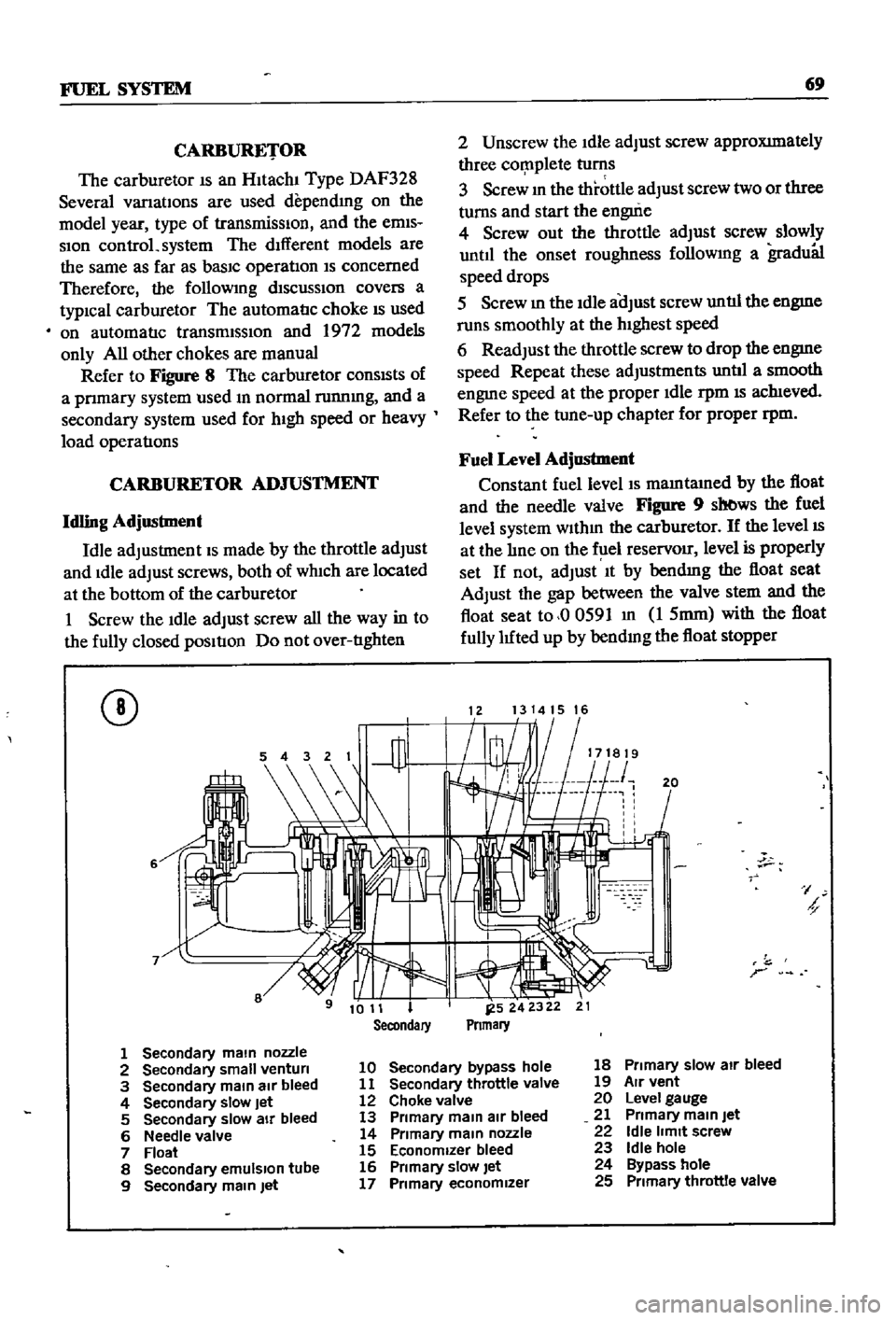
Refer
to
Figure
8
The
carburetor
conSIsts
of
a
pnmary
system
used
m
normal
runnmg
and
a
secondary
system
used
for
hIgh
speed
or
heavy
load
operatIons
CARBURETOR
ADJUSTMENT
Idling
Adjustment
Idle
adjustment
IS
made
by
the
throttle
adjust
and
Idle
adjust
screws
both
of
wh1ch
are
located
at
the
bottom
of
the
carburetor
1
Screw
the
Idle
adjust
screw
all
the
way
in
to
the
fully
closed
pOSItIon
Do
not
over
tIghten
CD
6
2
Unscrew
the
Idle
adjust
screw
approXImately
three
cor
nplete
turns
3
Screw
m
the
throttle
adjust
screw
two
or
three
turns
and
start
the
engui
e
4
Screw
out
the
throttle
adjust
screw
slowly
until
the
onset
roughness
followmg
a
gradu81
speed
drops
5
Screw
m
the
Idle
aOJust
screw
untIl
the
engme
runs
smoothly
at
the
hIghest
speed
6
Readjust
the
throttle
screw
to
drop
the
engme
speed
Repeat
these
adjustments
untIl
a
smooth
engme
speed
at
the
proper
Idle
rpm
IS
ach1eved
Refer
to
the
tune
up
chapter
for
proper
rpm
Fuel
Level
Adjustment
Constant
fuel
level
IS
mamtamed
by
the
float
and
the
needle
valve
Figure
9
sb
ws
the
fuel
level
system
wlthm
the
carburetor
If
the
level
IS
at
the
lIne
on
the
f
lel
reservOir
level
is
properly
set
If
not
adjust
It
by
bendmg
the
float
seat
Adjust
the
gap
between
the
valve
stem
and
the
float
seat
to
00591
m
1
5mm
with
the
float
fully
luted
up
by
bendmg
the
float
stopper
1213141516
20
I
h
r
1
Secondary
main
nozzle
2
Secondary
small
venturi
10
Secondary
bypass
hole
18
Primary
slow
air
bleed
3
Secondary
main
air
bleed
11
Secondary
throttle
valve
19
Air
vent
4
Secondary
slow
Jet
12
Choke
valve
20
Level
gauge
5
Secondary
slow
air
bleed
13
Primary
main
air
bleed
21
Primary
main
Jet
6
Needle
valve
14
Primary
main
nozzle
22
Idle
limit
screw
7
Float
15
Economizer
bleed
23
Idle
hole
8
Secondary
emulSion
tube
16
Primary
slow
let
24
Bypass
hole
9
Secondary
main
Jet
17
Primary
economizer
25
Primary
throttle
valve
Page 75 of 252
70
CHAPTER
SEVEN
CD
1
Float
seat
2
Roat
3
Roat
stopper
4
Needle
valve
Starting
Interlock
Valve
Opening
Adjustment
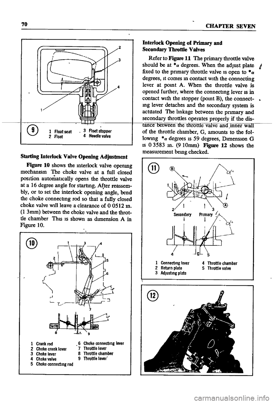
Figure
10
shows
the
Interlock
valve
openmg
mechanISm
The
choke
valve
at
a
full
closed
pOSItion
automatIcally
opens
the
throttle
valve
at
a
16
degree
angle
for
startlng
ter
reassem
bly
or
to
set
the
interlock
opening
angle
bend
the
choke
connectlng
rod
so
that
a
fully
closed
choke
valve
will
leave
a
clearance
of
0
0512
m
1
3mm
between
the
choke
valve
and
the
throt
tle
chamber
ThIS
IS
shown
as
dImension
A
in
Figure
10
@
7
1
Crank
rod
6
Choke
connecting
lever
2
Choke
crank
le
er
7
Throttle
lever
3
Choke
lever
8
Throttle
chamber
4
Choke
VBI
e
9
Throttle
lever
5
Choke
connecting
rod
Interlock
Opening
of
Primary
and
Secondary
Throttle
Valves
Refer
to
Figure
11
The
primary
throttle
valve
should
be
at
a
degrees
When
the
adjust
plate
I
fixed
to
the
pnmary
throttle
valve
IS
open
to
a
degrees
It
comes
In
contact
WIth
the
connecting
lever
at
pOInt
A
When
the
throttle
valve
is
opened
further
where
the
connectIng
lever
IS
in
contact
With
the
stopper
POInt
B
the
connect
mg
lever
detaches
and
the
secondary
system
is
actllated
The
lInkage
between
the
pnmary
and
secondary
throttles
operates
properly
if
the
dis
tance
6etween
theilirotlle
valve
anainner
will
of
the
throttle
chamber
G
amounts
to
the
fol
lowmg
a
degrees
IS
59
degrees
DImenSIon
G
IS
03583
In
910mm
Figure
12
shows
the
measurement
bemg
checked
@
2
Secondary
I
1
Connecting
le
er
2
Return
plate
3
Adjusting
plate
4
Throttle
chamber
5
Throttle
valve
I
1
I
r
t
i
t
r
1
I
j
I
00
I
r
@
Page 167 of 252

162
CHAPTER
TWELVE
14
Coat
the
front
bracket
pm
and
bushmg
and
shackle
pm
and
bushing
With
a
soap
solution
pnor
to
assembly
15
The
front
pm
secunng
nut
and
shock
ab
sorber
lower
end
securmg
nut
should
be
re
tightened
after
the
vehicle
is
sittmg
on
the
ground
16
Make
certaJn
the
shackle
bushmg
flange
is
clamped
evenly
on
both
Sides
SHOCK
ABSORBER
REMOVAL
INSPECTION
AND
INSTALLATION
WAGON
1
Jack
up
the
center
of
the
rear
axle
and
sup
port
th
e
axle
housmg
With
stands
2
Reinove
the
lower
end
of
the
rear
shock
absorber
from
spring
seat
3
Loosen
the
four
bolts
secunng
the
upper
bracket
to
body
Remove
shock
absorber
and
upper
bracket
4
Check
shock
absorber
for
leaks
and
cracks
Check
the
shaft
for
straighmess
Replace
1f
defective
5
Inspect
rubber
bushmgs
for
damage
cracks
and
general
condition
Replace
1f
defective
6
Install
the
shock
absorber
by
reversing
the
procedure
used
durmg
removal
DIFFERENTIAL
pICK
UP
The
dlfferenl1al
carner
IS
made
up
of
alum
mum
alloy
and
uses
a
hyp01d
bevel
gear
Proper
lubncatIon
IS
essenl1al
Check
and
replemsh
the
lubncant
every
3
000
mlles
Drain
and
refill
every
30
000
inlles
Figure
30
IS
a
cross
sectional
View
of
the
pick
up
dIfferential
Difterential
Removal
Pick
up
1
Jack
up
the
rear
wheels
and
support
vehicle
With
stands
2
DIsconnect
dnve
pmlOn
companlOn
flange
to
yoke
connectIon
3
Remove
rear
axles
as
descnbed
later
m
thIS
chapter
4
Remove
dlfferenl1al
gear
assembly
Difterential
Inspection
Pick
up
The
followmg
mspection
can
be
done
Without
disassembly
of
the
d1fferenl1al
If
abnormahties
or
damage
eXiSts
refer
further
serVice
and
reparr
to
your
dealer
1
Check
the
tooth
contact
pattern
WIth
lead
OXide
at
two
or
three
pomts
after
remoVlDg
rear
cover
Refer
to
FIgure
5
for
correct
contact
pattern
If
the
pattern
IS
faulty
disassembly
and
adJustment
of
the
dIfIerentialIs
required
2
Measure
backlash
between
dnve
gear
and
pmlOn
With
a
dial
mdlcator
Backlash
should
be
00051
to
0
0071
m
013
to
0
18mm
3
Rotate
the
gears
and
lISten
for
SignS
of
bear
mg
noise
4
Inspect
gear
teeth
for
SIgnS
of
damage
or
cracks
Difterential
Installation
Pick
up
Install
the
differential
by
reversmg
the
pro
cedures
used
dunng
removal
REAR
AXLE
AND
SUSPENSION
pICK
UP
The
rear
axle
IS
of
the
semi
floatIng
type
The
rear
wheels
use
tapered
roller
beanngs
Figure
31
IS
a
cross
sectional
view
of
the
rear
axle
REAR
SUSPENSION
TORQUE
TIGHTENING
SPECIFICATIONS
WAGON
Shock
absorber
upper
bracket
to
body
bolts
Shock
absorber
to
upper
bracket
lock
nuts
Shock
absorber
to
lower
bracket
lock
nuts
Rear
spnng
U
bolt
nuts
Shackle
nuts
Front
pm
nuts
Front
bracket
flxmg
nuts
Brake
dISC
to
rear
housmg
bolts
DifferentIal
carner
to
axle
housmg
bolt
Dnve
shaft
flange
nuts
11
to
18
ft
Ib
1
5
to
2
5
kg
m
12
to
16
ft
db
17
to
2
2
kg
m
25
to
33
ft
Ib
35
to
45
kg
m
43
to
47
ft
Ib
60
to
6
5
kg
m
32
to
36
ft
Ib
45
to
50
kg
m
32
to
36
ft
Ib
45
to
5
0
kg
m
13
to
17
ft
Ib
18
to
23
kg
m
20
to
28
ft
Ib
28
to
3
9
kg
m
14
to
16
ft
Ib
20
to
2
2
kg
m
20
to
28
ft
Ib
28
to
3
9
kg
m
Page 182 of 252
FRONT
AXLE
FRONT
SUSPENSION
AND
STEERING
177
5
Check
front
hub
for
cracks
and
damage
Re
place
1f
defectIve
6
Check
thrust
bearmg
for
wear
damage
rust
and
ease
of
rotatIon
Replace
1f
defectIve
Front
Suspension
Installation
1
Remstallation
is
the
reverse
of
removal
2
Apply
hght
coatIng
of
multI
purpose
grease
to
all
shdmg
parts
3
Install
bushmg
carefully
so
that
grease
groove
IS
on
the
upper
Side
and
the
bushmg
Joint
is
faced
rearward
Remove
grease
mpple
and
dn11
grease
hole
through
bushmg
through
hole
With
an
0
1181
m
3mm
dn11
Remove
metal
shaVlDgs
and
burrs
Ream
the
mner
d1ameter
of
the
bushing
to
07878
to
0
7888
m
20
010
to
20035mm
4
Install
thrust
bearmg
so
that
the
covered
face
Side
is
upward
5
Push
up
the
bottom
of
the
spmdle
hghtly
Measure
clearance
and
select
a
spmdle
shim
to
prOVide
the
followmg
clearance
standard
Clearance
0
001
In
004mm
ShIms
are
available
m
vanous
thicknesses
6
FIt
kmg
pm
and
make
certam
It
operates
smoothly
7
Apply
sealer
to
new
plug
and
install
8
Install
bearmg
outer
race
Fill
wheel
hub
and
hub
cap
With
multI
purpose
grease
Fill
space
between
wheel
bearing
rollers
and
grease
seal
hp
pocket
With
multI
purpose
grease
Make
cer
tam
wheel
beanngs
are
coated
completely
9
Apply
multI
purpose
grease
to
spmdle
shaft
wheel
bearmg
washer
and
to
the
wheel
bearmg
lock
nut
10
Make
certam
that
no
dIrt
or
foreign
matenal
IS
permitted
m
contact
with
parts
or
grease
dunng
assembly
Wheel
Bearing
Adjustment
1
Install
spindle
nut
and
torque
to
23
1
to
24
6
ft
lb
3
2
to
3
4
kg
m
2
Turn
wheel
hub
a
few
tImes
m
both
the
clock
Wise
and
counterclockwISe
directIon
Recheck
the
spmdle
nut
tighmess
3
Back
off
spmdle
nut
from
40
to
70
degrees
until
hole
m
spmdle
and
nut
COinCIde
Insert
cotter
pm
and
bend
over
around
nut
4
Turn
wheel
hub
a
few
turns
in
both
d1rectIons
to
seat
bearmg
Check
the
startmg
torque
of
the
hub
With
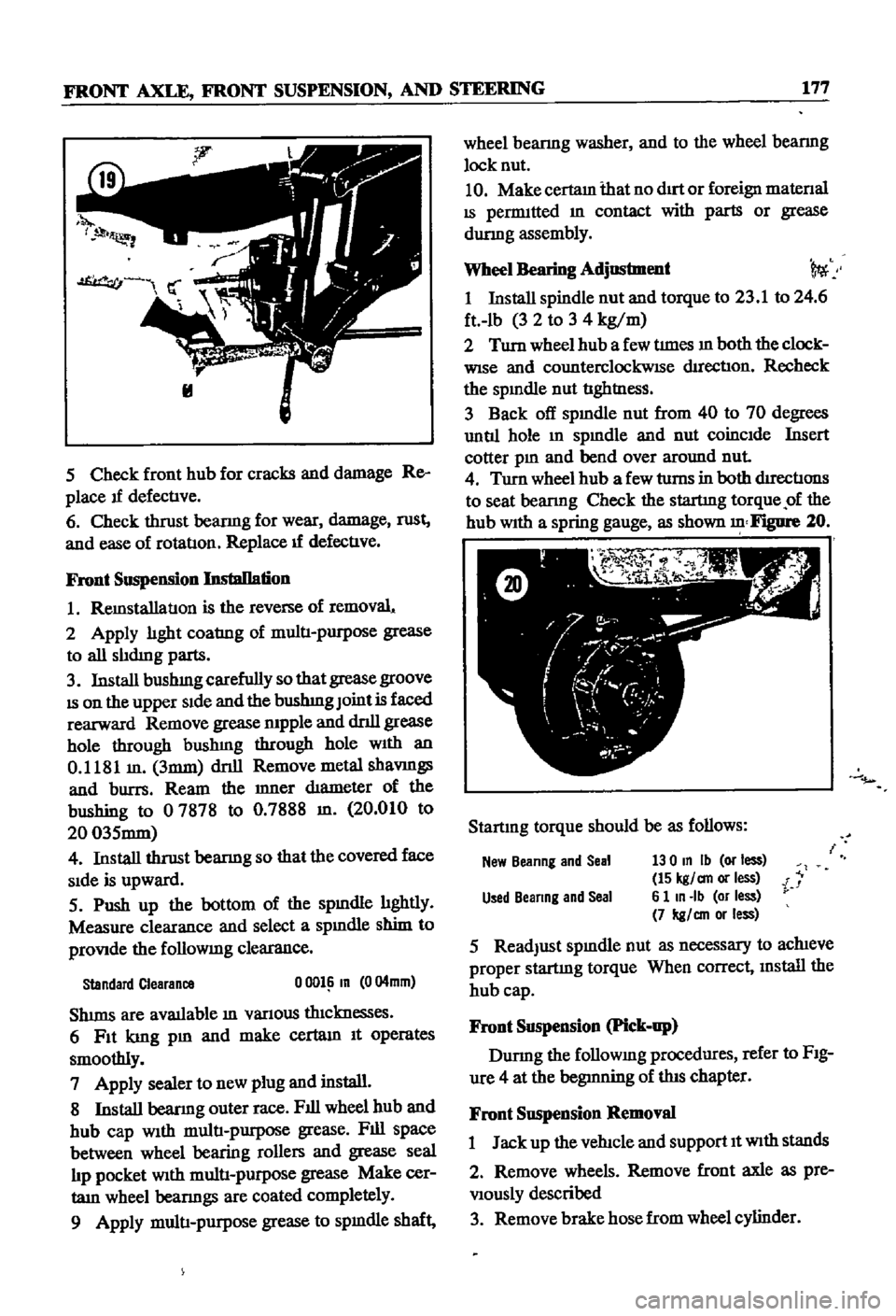
a
spring
gauge
as
shown
Figure
20
Startmg
torque
should
be
as
follows
New
Beanng
and
Seal
130
In
Ib
or
less
15
kgl
an
or
less
i
Used
Beanng
and
Seal
6
1
In
Ib
or
less
7
kgl
an
or
less
5
ReadJust
spmdle
nut
as
necessary
to
achieve
proper
startmg
torque
When
correct
mstall
the
hub
cap
Front
Suspension
Pick
up
Durmg
the
followmg
procedures
refer
to
FIg
ure
4
at
the
begmning
of
this
chapter
Front
Suspension
Removal
1
Jack
up
the
vehicle
and
support
It
With
stands
2
Remove
wheels
Remove
front
axle
as
pre
Viously
described
3
Remove
brake
hose
from
wheel
cylinder
Page 230 of 252
CHAPTER
SIXTEEN
ThIS
chapter
provides
infOrnl8tion
and
pro
cedures
for
removal
adJustment
and
or
re
placement
of
various
body
components
in
cluded
are
the
hood
front
trinl
doors
seats
locks
bumpers
tail
gates
and
door
and
window
controls
The
illustrations
given
are
typical
of
the
sedan
the
station
wagon
IS
similar
Details
on
the
pick
up
are
given
in
separate
illustrations
Other
body
repairs
require
special
knowledge
CD
L
BODY
and
tools
and
should
be
referred
to
your
Datsun
dealer
or
local
body
shop
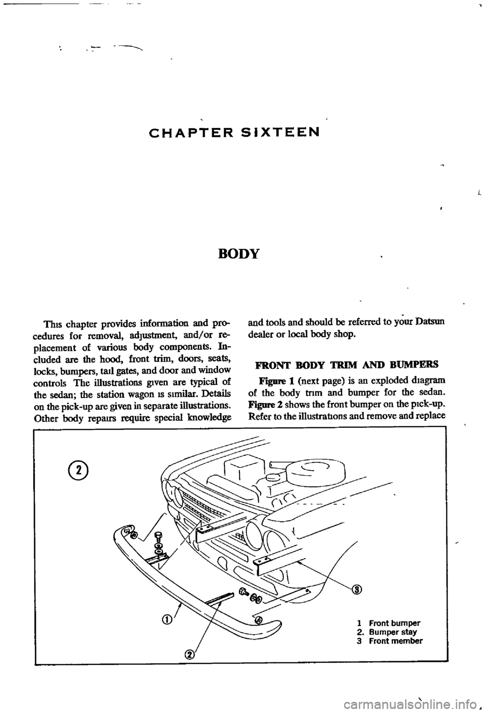
FRONT
BODY
TRIM
AND
BUMPERS
Figure
1
next
page
is
an
exploded
diagram
of
the
body
tnm
and
bumper
for
the
sedan
Figure
2
shows
the
front
bumper
on
the
pick
up
Refer
to
the
illustratIons
and
remove
and
replace
1
Front
bumper
2
Bumper
stay
3
Front
member
Page 241 of 252
INDEX
A
Inspection
and
repair
191
Air
cleaner
Pad
replacement
190
Exploded
views
63
64
Piston
seal
replacement
193
Removal
and
replacement
62
Reassembly
and
installation
193
Removal
190
Air
pump
40
Brakes
front
pick
up
Alternator
Brushes
104
Adjustment
201
Diode
103
Exploded
View
195
Disassembly
98
ServiCing
194
SpecdicatIons
194
203
204
Exploded
Views
41
99
Brakes
rear
pick
up
Inspection
and
repair
101
Adjustment
202
Output
checks
104
Exploded
View
195
Reassembly
104
Servicing
194
Removal
40
98
Brakes
rear
sedan
and
wagon
Rotor
102
Adjustment
202
Stator
102
Exploded
view
194
Axle
removal
pick
up
175
Inspection
and
repair
193
Reassembly
194
B
Removal
and
disassembly
193
Breaker
points
110
Ball
JOint
lower
sedan
and
wagon
174
Bumpers
Battery
Exploded
view
front
pick
up
223
Inspecllon
aiii
I
servicing
21
Exploded
View
front
sedan
and
wagon
224
SpeCific
gravity
21
Exploded
view
rear
sedan
230
Body
Exploded
view
rear
wagon
231
Body
Irlm
and
bumpers
223
224
Door
lock
and
regulator
225
C
Doors
225
Hood
lock
control
225
Camshaft
Seats
228
DeSCription
34
Tail
gate
228
Exploded
view
37
Trunk
hd
and
bumper
228
Inspection
48
Brake
pedal
Reassembly
54
Inspection
and
repair
187
Sprocket
53
Installation
188
Tlmmg
chain
57
Removal
187
Carburetor
Brakes
Cleaning
and
inspection
75
Adjustment
201
202
Dash
pot
adjustment
71
Bleeding
196
DesCription
37
69
Brake
pedal
187
Disassembly
71
Front
diSC
sedan
and
wagon
190
193
Exploded
Views
74
75
Front
drum
pick
up
194
Fuel
level
adjustment
69
Handbrake
197
201
Idhng
adjustment
69
Master
cyhnder
188
Interlock
valve
70
Rear
pick
up
194
Reassembly
76
Rear
sedan
and
wagon
193
Removal
40
71
SpeCifications
and
service
data
203
204
Sectional
view
69
Troubleshooting
16
Throttle
valve
70
Wheel
cyhnders
pIck
up
196
Charging
system
Brakes
front
diSC
sedan
and
wagon
Troubleshooting
12
Adjustment
201
Choke
and
accelerator
Disassembly
191
Disassembly
and
installation
82
Exploded
view
192
Exploded
view
83