Page 185 of 252

180
CHAPTER
TIlIRTEEN
@
44
6
1
756
Unit
mm
ln
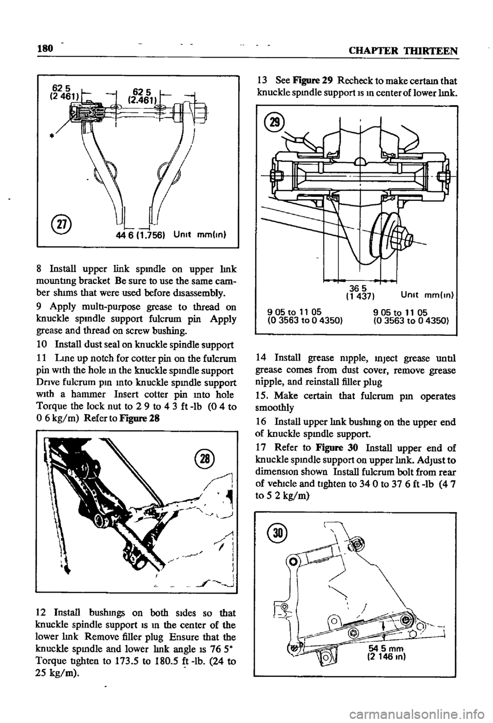
8
Install
upper
link
spmdle
on
upper
lmk
mountIng
bracket
Be
sure
to
use
the
same
cam
ber
shims
that
were
used
before
disassembly
9
Apply
multi
purpose
grease
to
thread
on
knuckle
spmdle
support
fulcrum
pin
Apply
grease
and
thread
on
screw
bushing
10
Install
dust
seal
on
knuckle
spindle
support
11
Lme
up
notch
for
cotter
pin
on
the
fulcrum
pin
With
the
hole
m
the
knuckle
spmdle
support
Dnve
fulcrum
pm
mto
knuckle
spmdle
support
With
a
hammer
Insert
cotter
pin
mto
hole
Torque
the
lock
nut
to
2
9
to
43ft
lb
0
4
to
o
6
kg
m
Refer
to
Figure
28
@
J
J
I
1
i
1
l
l
J
J
12
Install
bushmgs
on
both
Sides
so
that
knuckle
spindle
support
IS
m
the
center
of
the
lower
lmk
Remove
filler
plug
Ensure
that
the
knuckle
spmdle
and
lower
lmk
angle
IS
76
50
Torque
tighten
to
173
5
to
180
5
ft
lb
24
to
25
kg
m
13
See
Figure
29
Recheck
to
make
certam
that
knuckle
spmdle
support
IS
m
center
of
lower
lmk
365
1437
Unit
mm
ln
905to
11
05
0
3563
to
0
4350
905t01105
03563
to
04350
14
Install
grease
mpple
mJect
grease
until
grease
comes
from
dust
cover
remove
grease
nipple
and
reinstall
filler
plug
15
Make
certain
that
fulcrum
pm
operates
smoothly
16
Install
upper
lmk
bushmg
on
the
upper
end
of
knuckle
spmdle
support
17
Refer
to
Figure
30
Install
upper
end
of
knuckle
spmdle
support
on
upper
lmk
AdJust
to
dimenSIOn
shown
Install
fulcrum
bolt
from
rear
of
vehicle
and
tighten
to
340
to
376ft
lb
4
7
to
5
2
kg
m
@
54
5
mm
2
146
In
Page 186 of 252

FRONT
AXLE
FRONT
SUSPENSION
AND
STEERING
181
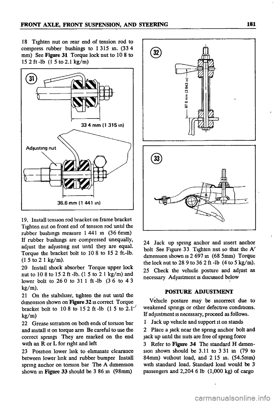
18
TIghten
nut
on
rear
end
of
tension
rod
to
compress
rubber
bushings
to
1
315
m
334
fi2
mm
See
Figure
31
Torque
lock
nut
to
10
8
to
152ft
lb
1
5
to
2
1
kg
m
334mm
1315m
36
6
mm
1
441
m
19
Install
tensiOn
rod
bracket
on
frame
bracket
Tighten
nut
on
front
end
of
tensIOn
rod
untll
the
rubber
bushmgs
measure
1441
m
366mm
If
rubber
bushmgs
are
compressed
unequally
adJust
the
adJusting
nut
until
they
are
equal
Torque
the
bracket
bolt
to
108
to
152
ft
lb
1
5
to
2
1
kg
m
20
Install
shock
absorber
Torque
upper
lock
nut
to
10
8
to
152ft
lb
1
5
to
2
1
kg
m
and
lower
bolt
to
260
to
311ft
lb
36
to
43
kg
m
21
On
the
stabilizer
tighten
the
nut
until
the
dimenSIOn
shown
on
Figure
32
IS
correct
Torque
bracket
bolt
to
10
8
to
152ft
lb
1
5
to
2
1
kg
m
22
Grease
serratIon
on
both
ends
of
torSiOn
bar
and
mstalllt
on
torque
arm
Be
careful
to
use
the
correct
spnngs
They
are
marked
on
the
end
WIth
an
R
or
L
for
nght
and
left
23
Position
lower
hnk
to
ehmmate
clearance
between
lower
hnk
and
rubber
bumper
Install
spnng
anchor
on
torsIOn
bar
The
A
dImenSiOn
shown
m
Figure
33
should
be
3
86
m
98mm
S
M
2
E
E
D
@
24
Jack
up
spnng
anchor
and
msert
anchor
bolt
See
Figure
33
Tighten
nut
so
that
the
A
mmenslon
shown
IS
2
697
m
68
5mm
Torque
the
lock
nut
to
28
9
to
362ft
lb
4
to
5
kg
m
25
Check
the
vehicle
posture
and
adJust
as
necessary
AdJustment
IS
dIScussed
below
POSTURE
AD
JUSTMENT
Vehicle
posture
may
be
mcorrcct
due
to
weakened
sprmgs
or
other
defective
conmtions
If
adJustment
IS
necessary
proceed
as
follows
1
Jack
up
vehicle
and
support
It
on
stands
2
Place
a
Jack
near
the
sprmg
anchor
bolt
and
Jack
up
until
the
nuts
are
free
of
spnng
force
3
Refer
to
Figure
34
The
standard
H
d1men
Slon
shown
should
be
3
11
to
331
m
79
to
84mm
Without
load
and
2
15
m
54
5mm
WIth
standard
load
Standard
load
would
be
3
passengers
and
2
204
6
lb
1
000
kg
of
cargo
Page 187 of 252

182
CHAPTER
TIllRTEEN
@
AdJust
the
anchor
bolt
adJustmg
nut
until
the
vehicle
posture
IS
correct
One
complete
turn
of
the
nut
will
change
the
vertIcal
measurement
by
approXlmately
0
133
in
3
Smm
WHEEL
AUGNMENT
Due
to
the
speclahzed
eqwpment
required
wheel
ahgnment
should
be
referred
to
a
Datsun
dealer
or
a
wheel
alignment
specIahst
The
fol
lowmg
specmcatIons
apply
to
the
pick
up
Caster
Camber
Kmg
Pm
Inclmatlon
Toe
In
1
50
1
15
6015
o
0787
to
0
1181
In
2
to
3mm
360
31
Steenng
Angle
Inner
Steenng
Angle
Outer
STEERING
SYSTEM
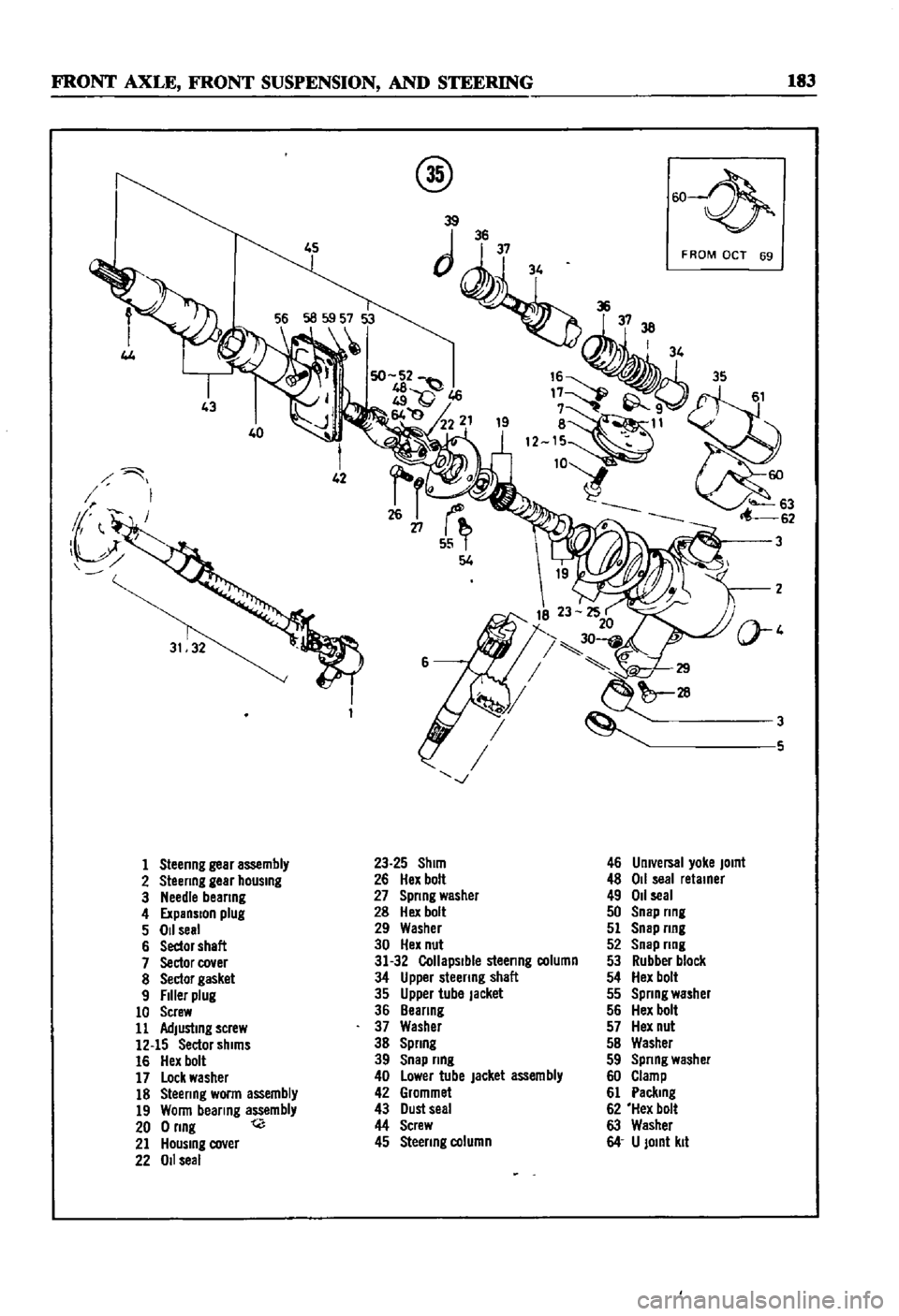
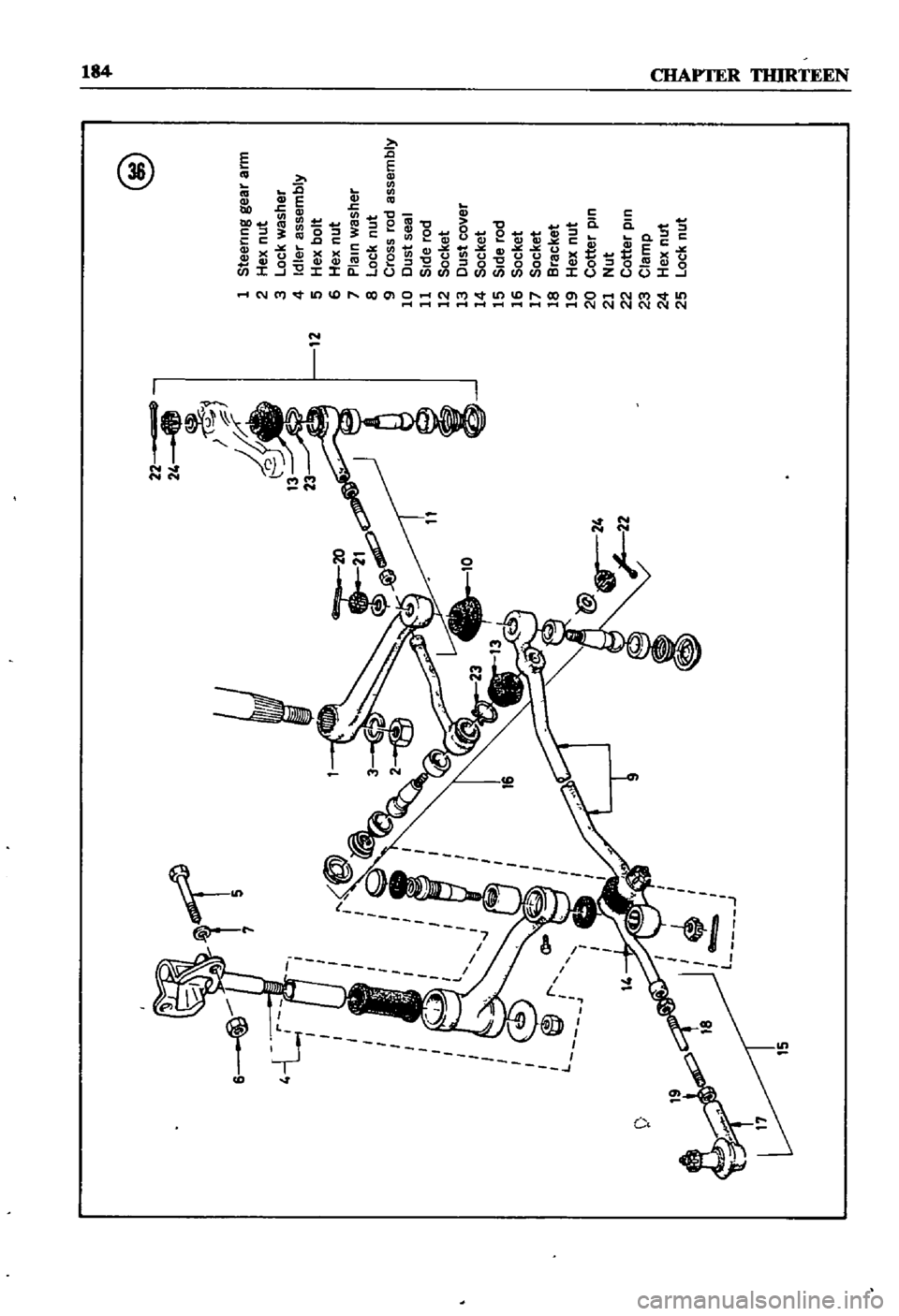
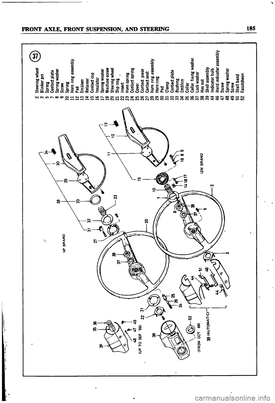
Figures
35
36
nnd
37
are
exploded
magrams
of
the
steenng
system
used
m
the
sedan
and
wagon
The
illustratIons
show
the
steenng
sys
tem
used
smce
1969
Earher
models
are
SImllar
m
constructiOn
and
operatIon
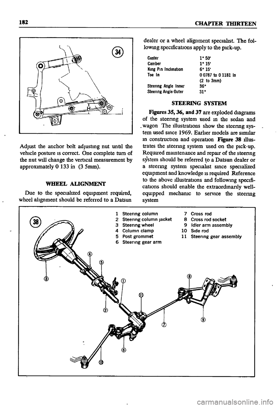
Figure
38
illus
trates
the
steenng
system
used
on
the
pick
up
ReqUIred
mamtenance
and
repaJr
of
the
steenng
system
should
be
referred
o
a
Datsun
dealer
or
a
steermg
system
specialISt
smce
specialized
eqwpment
and
knowledge
IS
required
Reference
to
the
above
Illustrations
and
followmg
specm
cations
should
enable
the
extraordmanly
well
equipped
mechanIC
to
serVice
the
steermg
system
1
Steenng
column
2
Steermg
column
Jacket
3
Steenng
wheel
4
Column
clamp
5
Post
grommet
6
Steenng
gear
arm
7
Cross
rod
8
Cross
rod
socket
9
Idler
arm
assembly
10
Side
rod
11
Steermg
gear
assembly
Page 188 of 252
FRONT
AXLE
FRONT
SUSPENSION
AND
STEERING
183
4J
40
1
Steenng
gear
assembly
2
Steenng
gear
hOUSing
3
Needle
beanng
4
ExpanSion
plug
5
011
seal
6
Sedor
shaft
7
Sector
cover
8
Sector
gasket
9
Filler
plug
10
Screw
11
Adjusting
screw
12
15
Sector
shims
16
Hex
bolt
17
Lock
washer
18
Steenng
worm
assembly
19
Wonn
bearing
assembly
200nng
t
21
HOUSing
cover
22
011
seal
@
w
39
JJii
3738
I
34
8
11
12
W63
62
23
25
Shim
26
Hex
bolt
27
Spnng
washer
28
Hex
bolt
29
Washer
30
Hex
nut
31
32
Collapsible
steenng
column
34
Upper
steenng
shaft
35
Upper
tube
Jacket
36
Beanng
37
Washer
38
Spnng
39
Snap
nng
40
Lower
tube
jacket
assembly
42
Grommet
43
Dust
seal
44
Screw
45
Steenng
column
F
ROM
OCT
69
3
3
5
46
Umversal
yoke
JOint
48
011
seal
retainer
49
011
seal
50
Snap
nng
51
Snap
nng
52
Snap
nng
53
Rubber
block
54
Hex
bolt
55
Spnng
washer
56
Hex
bolt
57
Hex
nut
5B
Washer
59
Spnng
washer
60
Clamp
61
Paclung
62
Hex
bolt
63
Washer
64
U
JOint
kit
Page 189 of 252
15
7
5
l
J
@
1
Steermg
gea
r
arm
2
Hex
nut
3
Lock
washer
4
Idler
assembly
12
5
Hex
bolt
6
Hex
nut
7
Plam
washer
8
Lock
nut
9
Cross
rod
assembly
10
Dust
seal
11
Side
rod
12
Socket
13
Dust
cover
14
Socket
15
Side
rod
16
Socket
17
Socket
18
Bracket
19
Hex
nut
20
Cotter
pm
21
Nut
22
Cotter
pm
23
Clamp
24
Hex
nut
25
Lock
nut
00
Page 190 of 252
NP
BRAND
3536
48
47
49
UP
TO
SEP
69
15
10
l
f
J
r
1
L
IZM
BRAND
39
39
AUTOMATIC
2
Steering
wheel
@
3
Blinker
pin
5
Spring
7
Contact
plate
8
Spring
washer
9
Screw
10
Spring
11
Horn
ring
assembly
12
Pad
13
Emblem
14
Retainer
15
Contact
cup
16
Insulator
17
Spring
washer
18
Machine
screw
20
Steering
wheel
21
Slip
ring
22
Insert
23
Horn
spring
24
Contact
spring
25
Cover
26
Contact
pleca
27
Contact
seat
28
Horn
ring
assembly
29
Horn
ring
30
Pad
31
Clamp
32
Contact
plate
33
Bushing
34
Emblem
35
Collar
36
Collar
fiXing
washer
37
Lock
washer
38
Hex
nut
39
Shell
assembly
44
Indicator
bulb
46
Hand
indicator
assembly
47
Scraw
48
Spring
washer
49
Screw
51
Shell
band
52
Escutcheon
o
I
l
I
l
i
J
I
Ci
l
QD
II
L
Page 191 of 252
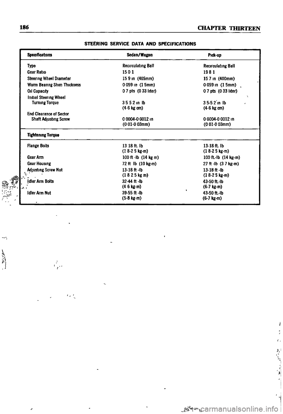
186
CHAPTER
TIURTEEN
STEERING
SERVICE
DATA
AND
SPECIFICATIONS
r
SpeaficatJons
Sedan
Wagon
P1c11
up
Type
Reclrculatmg
Ball
Reclrculatmg
Ball
Gear
Ratio
1501
1981
Steenng
Wheel
Diameter
159m
405mm
157m
400mm
Wonn
Beanng
Shim
Thickness
0059
m
1
5mm
0059
m
1
5mm
011
CapacJ
y
o
7
pts
0
33
hter
o
7
pts
0
33
hter
Imtlal
Steering
Wheel
Turnmg
Torque
3552mlb
3
5
5
2
In
Ib
4
6
kg
an
4
6
kg
an
End
Clearance
of
Sector
Shaft
AdJustmg
Screw
o
0004
0
0012
m
00004
00012
m
0
01
0
03mm
0
01
0
03mm
Tiglrtenlng
Torque
Flange
Bolts
13
18
ft
Ib
13
18
ft
Ib
1
8
2
5
kg
m
1
8
2
5
kg
m
Gear
Ann
100
ft
Ib
14
kg
m
100
ft
lb
14
kg
m
Gear
Housmg
72
ft
Ib
10
kg
m
27
ft
Ib
3
7
kg
m
dJustmg
Screw
Nut
13
18
ft
Ib
13
18
ft
Ib
y
1
8
2
5
kg
m
1
8
2
5
kg
m
dler
Ann
Bolts
32
44
ft
rb
43
50
ft
Ib
4
6
kg
m
6
7
kg
m
Idler
Arm
Nut
39
55
ft
Ib
43
50
ft
lb
5
8
kg
m
6
7
kg
m
St
I
j
i
I
i
1
l
I
I
Page 192 of 252
CHAPTER
FOURTEEN
BRAKES
The
sedan
and
station
wagon
are
equipped
With
disc
brakes
on
the
front
wheels
drum
brakes
on
the
rear
wheeis
and
a
tandem
master
cyhnder
The
pIck
up
has
drum
brakes
on
all
four
wheels
and
a
single
master
cylmder
All
vehicles
have
a
mechanIcal
handbrake
that
works
on
the
rear
wheels
only
BRAKE
PEDAL
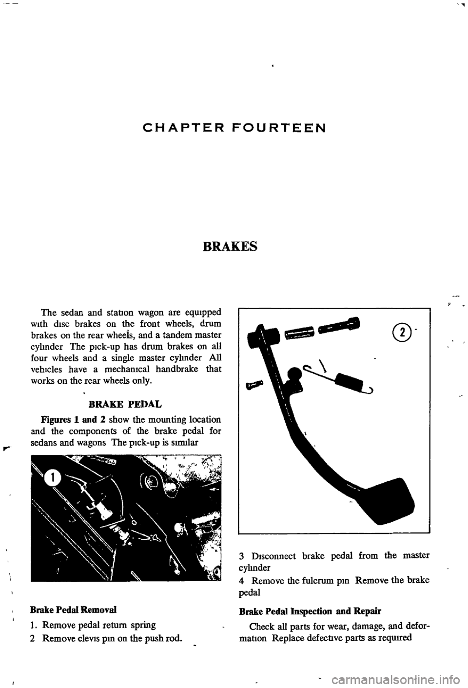
Figures
1
and
2
show
the
mounting
location
and
the
components
of
the
brake
pedal
for
sedans
and
wagons
The
pick
up
is
smlliar
Brake
Pedal
Removal
1
Remove
pedal
return
spring
2
Remove
cleViS
pm
on
the
push
rod
CD
3
Disconnect
brake
pedal
from
the
master
cyhnder
4
Remove
the
fulcrum
pm
Remove
the
brake
pedal
Brake
Pedal
Inspection
nnd
Repair
Check
all
parts
for
wear
damage
and
defor
matIon
Replace
defective
parts
as
reqwred