1968 DATSUN 510 oil temperature
[x] Cancel search: oil temperaturePage 11 of 252

CHAPTER
TWO
PERIODIC
MAINTENANCE
To
ensure
good
performance
dependability
and
safety
regular
penodlc
maintenance
is
necessary
TIns
chapter
outlInes
routine
and
penodlc
mamtenance
for
the
average
dnver
Under
heavy
usage
semcmg
mtervals
will
be
shortened
Regular
routme
mamtenance
will
help
aVOId
expensive
repaIrs
ROUTINE
CHECKS
The
followlDg
checks
should
be
performed
at
each
fuel
stop
1
Check
engme
oil
level
Top
up
as
requrred
2
Check
radiator
coolant
level
Top
up
as
re
qwred
3
Check
battery
electrolyte
The
battery
case
IS
marked
With
upper
hrmt
and
lower
lnmt
lInes
Level
should
be
maID
tamed
between
the
IIDes
4
Check
that
the
master
cylInder
brake
flwd
reservOir
level
IS
between
the
max
and
mm
lInes
marked
on
the
plastic
case
S
Check
the
plastic
clutch
cyhnder
reservoir
level
Level
should
be
between
the
max
and
mm
lInes
6
Check
the
windsh1eld
washer
flwd
reservoir
Top
up
as
required
7
Check
tire
pressures
when
the
tIres
are
cold
Front
and
rear
tire
pressures
should
be
24
pounds
under
normal
dnving
conditions
TIre
pressure
should
be
28
pounds
for
h1gh
speed
dnvmg
conditions
8
Check
the
engIne
for
general
conditIon
Check
for
leaky
or
cracked
hoses
and
loose
wmng
9
Check
condition
of
wmdshleld
wiper
blades
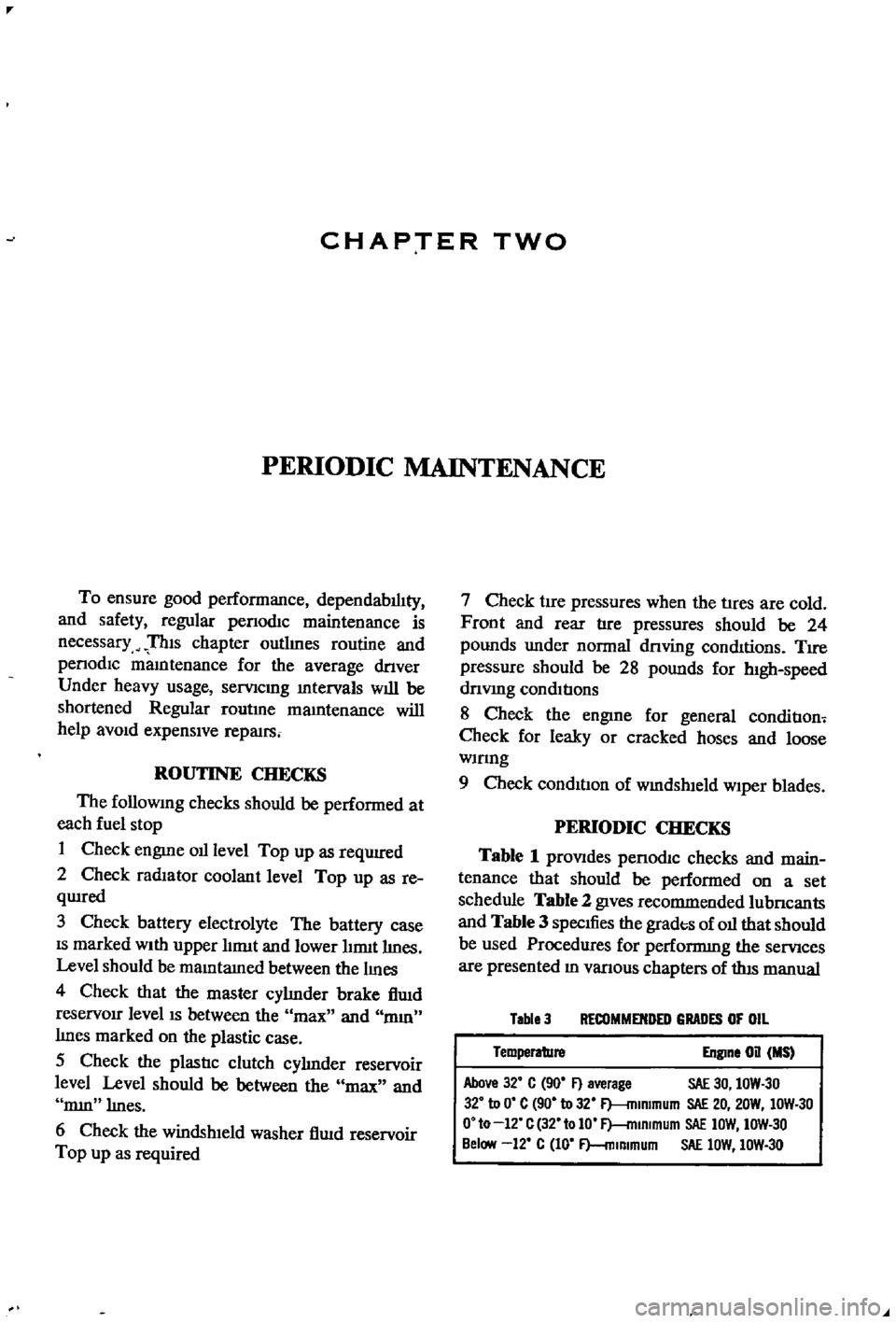
PERIODIC
CHECKS
Table
1
prOVIdes
penodIc
checks
and
main
tenance
that
should
be
performed
on
a
set
schedule
Table
2
gIves
recommended
lubncants
and
Table
3
specIfies
the
grades
of
oil
that
should
be
used
Procedures
for
performmg
the
semces
are
presented
ID
vanous
chapters
of
tlus
manual
Table
3
RECOMMENDED
GRADES
OF
OIL
Temperature
Engine
on
MS
Above
32
C
90
F
average
SAE
30
IOW
30
32
to
0
C
90
to
32
F
mlmmum
SAE
20
20W
IOW
30
O
to
12
C
32
tolO
F
mlRlmum
SAE
IOW
IOW
30
Below
12
C
10
F
mlmmum
SAE
lOW
IOW
30
Page 29 of 252

P
r
OVll
t
ate
I
l
h
l
JlA
ye
I
o
ctg
fI
O
0
I
d
1e
d
c
Ji
uo
JJ
cb
c
s
rlr
I
l
4
c
1
2
24
CHAPTER
FOUR
block
and
should
be
used
as
the
reference
point
m
II
1akmg
adjustments
6
With
a
piece
of
white
chalk
mark
a
hne
down
the
center
of
the
pomter
and
mark
the
timing
groove
on
the
crankshaft
pulley
which
IS
to
be
used
m
tImmg
the
engine
SpecIficatIon
for
tun
ing
reqUIres
trlhmg
at
10
degrees
before
top
dead
center
wluch
would
be
the
fourth
mark
from
the
left
end
of
the
row
of
marks
7
Loosen
the
hold
down
bolt
at
the
base
of
the
dlstnbutor
8
Locate
the
slow
speed
1
Ile
adjustIng
screw
on
the
carburetor
so
that
Ile
speed
can
be
adjusted
whIle
runnmg
Also
locate
throttle
adJustmg
screw
9
Start
engme
and
adjust
speed
With
the
adJust
ing
screws
to
the
readmgs
below
Smgle
pomt
dIStributor
600
rpm
Dual
pomt
trlbutor
700
rpm
10
Alternate
adjustment
of
the
two
screws
untIl
the
smoothest
Idle
at
the
proper
speed
IS
achieved
11
Pomt
the
tlIrung
lIght
at
the
stationary
pomter
When
the
lIght
flashes
the
timmg
mark
n
the
crankshaft
pulley
should
hne
up
With
the
mark
on
the
stationary
pomter
If
It
does
not
exactly
Ime
up
rotate
the
dlstnbutor
gradually
untIl
the
marks
align
mdlcatlng
correct
timmg
12
Shut
off
the
engme
remove
the
tmung
lIght
and
tachometer
tighten
the
hold
down
bolt
on
the
dlStnbutor
and
connect
the
vacuum
advance
hne
to
the
tli
tnbutor
IGNITION
TIMING
IDLE
SPEED
IDLE
MIXTURE
DUAL
POINT
DISTRIBUTOR
ONLY
The
followmg
applies
to
velucles
With
dual
pomt
distributor
and
an
exhaust
emission
con
trol
deVice
If
these
procedures
are
followed
ha
ul
exhaust
emisSion
should
be
below
the
maximum
allowable
level
1
Locate
the
Idle
and
throttle
adJustmg
screws
on
the
carburetor
2
Warm
up
the
engine
thoroughly
3
Connect
tachometer
and
tmung
light
4
Set
the
Id
le
speed
at
700
rpm
With
the
Idle
adjust
screw
5
Adjust
IgnltJ
on
tuning
at
10
degrees
before
top
dead
center
6
Increase
the
speed
of
the
engme
to
2
000
rpm
With
the
accelerator
or
throttle
hnkage
and
hold
for
about
15
seconds
7
Return
to
Idle
for
one
mmute
8
Set
the
engme
to
best
Idle
at
750
rpm
770
rpm
for
automatJ
c
transIDlsslOn
With
the
Idle
and
throttle
adJustmg
screws
9
Re
uce
engme
speed
at
700
rpm
720
rpm
for
automatic
transmission
by
turnmg
the
Idle
adJustmg
screw
clockWise
for
a
leaner
IlliXture
10
Connect
a
wife
lead
between
the
advance
ami
retard
Side
tenrunals
See
Figure
4
Speed
should
drop
from
100
to
150
rpm
11
Check
IgIl1tIon
tmung
With
tImmg
light
It
should
now
be
at
top
d
ad
center
12
If
the
tlmmg
IS
nSJt
correct
stop
the
engme
and
adjust
the
retarded
breaker
pomt
13
Start
the
engme
and
reclieck
ili
tmung
If
l
incorrect
reset
the
retarded
breaker
pomt
until
it
IS
correct
Repeat
s
nece
s
14
Disconnect
the
wife
bet
reen
the
advance
and
retard
termmals
15
Recheck
tmung
It
should
be
10
degrees
before
top
dead
center
16
If
mcorrect
repeat
the
above
procedures
un
tIl
satIsfactory
17
T
he
Idle
speed
of
automatic
transnllsslOn
vehicles
should
be
about
575
rpm
With
the
gear
j
selector
m
the
dhve
poSltlon
c
t
DWELL
ANGLE
SETIING
1
Connect
the
dwell
angle
meter
2
PLoJust
dwell
angle
to
49
to
55
degrees
OMPRESSION
TEST
I
A
compressIOn
test
IS
performed
to
check
for
worn
piston
nngs
or
to
detect
the
cause
of
a
low
speed
miss
Before
undertaking
the
test
el
llmate
the
pOSSibility
of
sticky
valves
by
usmg
one
of
the
oil
additives
deSigned
for
the
purpose
With
valves
free
test
compressIOn
as
follows
1
Run
the
engme
for
15
to
20
mmutes
untIl
normal
operating
temperatures
are
obtained
2
Shut
off
engme
remove
arr
cleaner
and
Page 30 of 252

ENGINE
AND
IGNITION
TUNE
UP
4
25
block
the
throttle
and
choke
m
the
WIde
open
position
3
Remove
all
four
spark
plugs
4
Sequentially
press
a
compressIOn
test
gauge
mto
each
of
the
spark
plug
holes
and
crank
the
engme
for
at
least
four
strokes
Record
the
com
pressIOn
readmg
for
each
cylmder
Standard
compressIOn
readmg
IS
171
Ibs
m
12
0
kg
cm
Mmlmum
acceptable
readmg
IS
159
lbs
m
2
11
5
kg
cm
5
No
readmg
should
be
less
than
80
of
the
highest
cylmder
reading
ExceSSive
vanatiC
ns
between
cylmders
accompanied
by
low
speed
mlssmg
of
the
cyhnder
or
cylmders
that
read
low
usually
mdlcates
a
valve
not
properly
seat
mg
or
a
broken
piston
ring
Low
pressures
even
though
uniform
may
mdicate
worn
nngs
ThIS
IS
especlall
true
1f
ex
cessive
011
cQIlsumptlon
has
been
noticed
If
one
or
more
cylmders
read
low
or
uneven
inject
about
a
tablespoon
of
engine
ail
on
top
of
the
piston
of
that
cylinder
and
crank
the
engine
several
tlmes
noting
the
compressIOn
reading
If
compressIOn
has
nsen
the
piston
nngs
or
cylmders
are
worn
and
should
befserviced
If
compressIOn
has
not
unproved
after
addmg
oil
the
valves
are
Stlcking
or
are
not
seating
prop
erly
If
two
adjacent
cylmders
have
low
compres
sion
and
mjectmg
01
9es
not
increas
the
read
mg
the
head
gasket
between
the
cylmders
IS
probably
leaking
VALVE
CLEARANCE
ADJUSTMENT
Valve
adjustment
should
be
done
in
two
steps
first
With
the
engme
cold
and
then
at
operatmg
temperature
Refer
to
Figure
6
and
proceed
as
follows
1
Remove
arr
liter
2
Remove
rocker
arm
cover
Take
care
not
to
damage
the
gasket
3
Remove
the
spark
plugs
and
rotate
the
en
gine
unt1l
number
1
cylinder
IS
at
top
dead
center
o
l
the
compressIOn
stroke
This
can
be
de
tepnmed
w
hen
the
top
dead
center
mark
on
the
crankshaft
pulley
is
m
alignment
With
the
statIOnary
pomter
and
both
valves
for
number
1
cylmder
are
closed
I
4
Counting
from
the
front
of
the
engme
ad
Just
valves
1
2
3
and
5
as
follows
Loosen
the
pivot
lockmg
nut
and
turn
the
pivot
screw
unt1l
clearance
between
the
pivot
screw
and
the
rock
er
ann
IS
0
0079
m
0
200mm
for
the
mtake
valves
and
0
0098
in
0
25mm
for
the
exhaust
valves
Check
clearances
With
a
feeler
gauge
as
shawn
When
correct
tlghten
the
pivot
locking
nut
l
1
5
Rotate
the
crankshaft
unt1l
the
number
4
pISton
IS
at
top
dead
center
an
the
compressIOn
stroke
This
IS
one
complete
revolution
of
the
crankshaft
Agam
the
0
degree
mark
should
align
With
the
pomter
and
both
valves
on
num
ber
4
cylinder
should
be
closed
6
Adjust
valves
4
6
7
and
8
as
above
i
I
7
Replace
spark
plugs
Ignition
WIres
r
ick
r
1
arm
cover
gasket
and
air
filter
8
Start
engine
and
run
it
unt1l
operating
tem
perature
IS
reached
9
Remove
rocker
ann
cover
and
repeava
iius
ment
Clearances
should
be
0
0098
m
0
25fumj
for
the
mtake
valves
and
00Il8
m
0
30mi
for
the
exhaust
valves
Check
clearances
before
loosening
the
pivot
lockmg
nuts
as
they
may
already
be
properly
set
If
not
adjust
as
re
quir
l
ADDmONAL
CHECKS
l
Qunng
tune
ups
check
the
followmg
Ite
far
SignS
of
defects
or
excessive
wear
I
i
1
Inspect
the
carburetor
for
buildup
of
foreign
matenal
Pay
Special
attention
to
the
throat
and
linkages
Clean
or
overhaul
as
required
Det8
1ls
for
carburetor
mamtenance
are
given
in
Chapter
seven
Page 41 of 252

36
CHAPTER
SIX
0B
34
35
2224
19
21
p
7
31
13
4
7
O
41
rlj
17
11
lOlL
JET
2
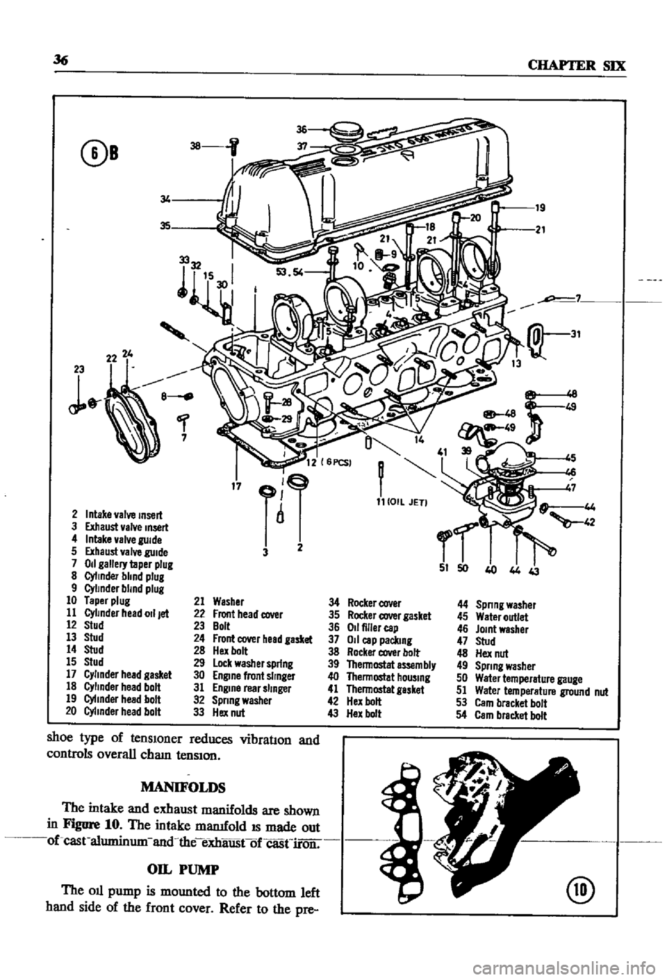
Intake
valve
Insert
3
Exhaust
valve
Insert
4
Intake
valve
guide
5
Exhaust
valve
guide
3
2
7
Od
gallery
taper
plug
I
441
J
8
Cylinder
blind
plug
9
Cylinder
blind
plug
10
Taper
plug
21
Washer
34
Rocker
cover
44
Spnng
washer
11
Cylinder
head
011
jet
22
Front
head
cover
35
Rocker
cover
gasket
45
Water
outlet
12
stud
23
Bolt
36
Od
filler
cap
46
JOint
washer
13
stud
24
Front
cover
head
gasket
37
011
cap
paclung
47
stud
14
stud
28
Hex
bolt
38
Rocker
cover
bolt
48
Hex
nut
15
Stud
29
lock
washer
spring
39
Thennostat
a5sem
bly
49
Spring
washer
17
Cylinder
head
gasket
30
Engine
front
Slinger
40
Thennostat
hOUSing
50
Water
temperature
gauge
18
Cylinder
head
bolt
31
Engine
rear
slinger
41
Thennostat
gasket
51
Water
temperature
ground
nut
19
Cylinder
head
bolt
32
Spnng
washer
42
Hex
bolt
53
Cam
bracket
bolt
20
Cylinder
head
bolt
33
Hex
nut
43
Hex
bolt
54
Cam
bracket
bolt
shoe
type
of
tensIOner
reduces
vibration
and
controls
overall
cham
tenSIOn
MANIFOLDS
The
intake
and
exhaust
manifolds
are
shown
in
Figure
10
The
intake
mamfold
IS
made
out
of
cast
aluminum
and
the
eXhaustof
casn
roir
OIL
PUMP
The
oil
pump
is
mounted
to
the
bottom
left
hand
side
of
the
front
cover
Refer
to
the
pre
@
Page 43 of 252

38
CHAPTER
SIX
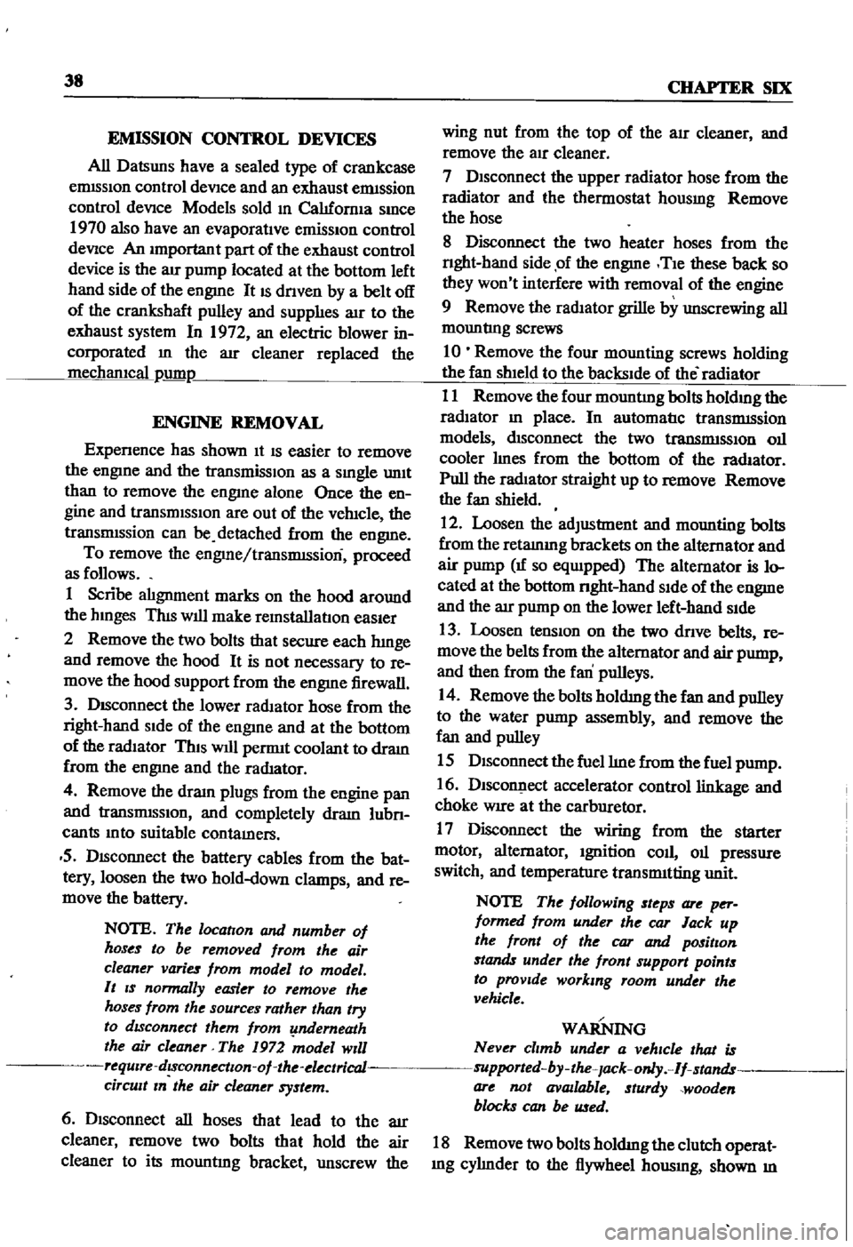
EMISSION
CONTROL
DEVICES
All
Datsuns
have
a
sealed
type
of
crankcase
emISSion
control
device
and
an
exhaust
emISsion
control
deVice
Models
sold
m
Cahfornla
smce
1970
also
have
an
evaporative
emisSion
control
deVice
An
rmportant
part
of
the
exhaust
control
device
is
the
air
pump
located
at
the
bottom
left
hand
side
of
the
engme
It
IS
dnven
by
a
belt
off
of
the
crankshaft
pulley
and
supphes
air
to
the
exhaust
system
In
1972
an
electric
blower
in
corporated
m
the
air
cleaner
replaced
the
mechanical
pumI
ENGINE
REMOVAL
Expenence
has
shown
It
IS
easier
to
remove
the
engine
and
the
transmission
as
a
smgle
UnIt
than
to
remove
the
engme
alone
Once
the
en
gine
and
transmiSSIon
are
out
of
the
vehIcle
the
tranSmIssion
can
be
detached
from
the
engme
To
remove
the
engme
transmISsion
proceed
as
follows
1
Scribe
ahgnment
marks
on
the
hood
around
the
hmges
ThIS
will
make
remstallatlon
eaSIer
2
Remove
the
two
bolts
that
secure
each
hInge
and
remove
the
hood
It
is
not
necessary
to
re
move
the
hood
support
from
the
engme
firewall
3
DISconnect
the
lower
radIator
hose
from
the
right
hand
SIde
of
the
engine
and
at
the
bottom
of
the
radIator
ThIS
will
pernnt
coolant
to
dram
from
the
engme
and
the
radIator
4
Remove
the
draIn
plugs
from
the
engine
pan
and
translIDSsIon
and
completely
dram
lubn
cants
Into
suitable
contamers
5
DISconnect
the
battery
cables
from
the
bat
tery
loosen
the
two
hold
down
clamps
and
re
move
the
battery
NOTE
The
location
and
number
of
hoses
to
be
removed
from
the
air
cleaner
varies
from
model
to
model
It
IS
normally
easier
to
remove
the
hoses
from
the
sources
rather
than
try
to
dISconnect
them
from
yndemeath
the
air
cleaner
The
1972
model
Will
requlre
dlsconnectlOn
of
the
electrica1
cirCUit
In
the
air
cleaner
system
wing
nut
from
the
top
of
the
air
cleaner
and
remove
the
aIr
cleaner
7
DIsconnect
the
upper
radiator
hose
from
the
radiator
and
the
thermostat
housmg
Remove
the
hose
8
Disconnect
the
two
heater
hoses
from
the
nght
hand
side
of
the
engme
TIe
these
bac
so
they
won
t
interfere
with
removal
of
the
engme
9
Remove
the
radIator
grille
by
unscrewing
all
mountmg
screws
10
Remove
the
four
mounting
screws
holding
the
fan
shield
to
the
backside
of
the
radiator
11
Remove
the
four
mountmg
bolts
holdIng
the
radiator
In
place
In
automatic
tranSmISsion
models
dISconnect
the
two
transnnsslOn
oIl
cooler
lInes
from
the
bottom
of
the
radiator
Pull
the
radiator
straight
up
to
remove
Remove
the
fan
shield
12
Loosen
the
adjustment
and
mounting
bolts
from
the
retamIng
brackets
on
the
alternator
and
air
pump
If
so
eqwpped
The
alternator
is
lo
cated
at
the
bottom
nght
hand
Side
of
the
engme
and
the
air
pump
on
the
lower
left
hand
Side
13
Loosen
tenSIon
on
the
two
dnve
belts
re
move
the
belts
from
the
alternator
and
air
pump
and
then
from
the
fan
pulleys
14
Remove
the
bolts
holdIng
the
fan
and
pulley
to
the
water
pump
assembly
and
remove
the
fan
and
pulley
15
DISconnect
the
fuel
hne
from
the
fuel
pump
16
DIsco
ect
accelerator
control
linkage
and
choke
WIre
at
the
carburetor
17
Disconnect
the
wiring
from
the
starter
motor
alternator
Ignition
coIl
oIl
pressure
switch
and
temperature
transmItting
unit
NOTE
The
following
steps
are
per
formed
from
under
the
car
lack
up
the
front
of
the
car
and
position
stands
under
the
front
support
points
to
proVide
working
room
under
the
vehicle
WARNING
Never
climb
under
a
vehicle
that
is
supported
by
the
lack
only
If
stands
are
not
avflllable
sturdy
wooden
blocks
can
be
U3ed
6
Disconnect
all
hoses
that
lead
to
the
air
cleaner
remove
two
bolts
that
hold
the
air
cleaner
to
its
mountmg
bracket
unscrew
the
18
Remove
two
bolts
holdIng
the
clutch
operat
Ing
cylInder
to
the
flywheel
hOUSIng
shown
m
Page 152 of 252

CLUTCH
TRANSMISSION
AND
DRIVESHAFI
147
SERVICE
DATA
AND
SPECIFICATIONS
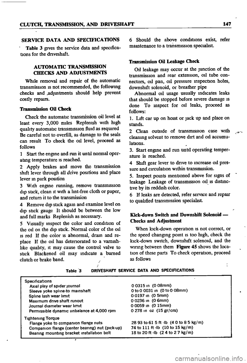
Table
3
gives
the
service
data
and
specIfica
tIons
for
the
dnveshaft
AUTOMATIC
TRANSMISSION
CHECKS
AND
ADJUSTMENTS
Whlle
removal
and
repair
of
the
automatic
transmisSIOn
IS
not
recommended
the
follo
VlIlg
checks
and
adjustments
should
help
prevent
costly
repatrs
Transmission
Oil
Check
Check
the
automatIc
transmission
oil
level
at
least
every
3
000
mlles
Replemsh
With
hIgh
qualIty
automatIc
transmISSIon
flUId
as
reqUIred
Be
careful
not
to
overfill
as
damage
to
the
seals
can
result
To
check
the
011
level
proceed
as
follows
1
Start
the
engme
and
nm
it
untIl
normal
oper
atrng
temperature
IS
reached
2
Apply
brakes
and
move
the
transmission
shut
lever
through
all
drive
pOSItions
and
place
lever
In
park
position
3
WIth
engme
running
remove
tranSmISSIon
dIp
StIck
clean
It
WIth
a
lInt
free
cloth
or
paper
and
return
it
to
the
transmission
4
Remove
dIp
stIck
agam
and
examine
level
on
dIp
stIck
gauge
It
should
be
between
the
low
and
full
marks
Replenish
as
necessary
5
VIsually
InSpect
the
color
and
condItIon
of
the
OIl
on
the
dIp
stIck
Normal
color
of
the
OIl
IS
red
If
the
color
IS
abnormal
dram
and
re
place
If
the
011
has
detenorated
to
a
vamlsh
lIke
qualIty
It
may
cause
the
control
valve
to
stIck
Blackened
oil
may
mdlcate
a
burned
clutch
or
brake
band
6
Should
the
above
condItIons
exist
refer
mamtenance
to
a
transmISSIon
specIalIst
Transmission
Oil
Leakage
Check
011
leakage
may
occur
at
the
Junction
of
the
transmissIon
and
rear
extensIon
011
tube
con
nectors
011
pan
OIl
pressure
mspectIon
holes
downshIft
solenoid
or
breather
pipe
Abnormal
OIl
usage
usually
mdlcates
leaks
that
should
be
stopped
before
severe
damage
IS
done
To
mspect
for
011
leaks
proceed
as
follows
1
LIft
car
up
on
hOISt
or
Jack
up
and
place
on
stands
2
Clean
outsIde
of
transmISSIon
case
With
cleanIng
solvent
to
remove
dIrt
and
011
accumu
latIons
3
Start
engme
and
nm
untIl
operating
temper
ature
is
reached
4
ShIft
gear
lever
to
dnve
to
Increase
011
pres
sure
and
CIrculatIon
WIthin
tranSmISsion
5
Inspect
pOInts
mentIoned
above
for
SIgnS
of
leakage
Leakage
of
transrmSSIOn
011
IS
dIStrnC
tIve
by
its
reddISh
color
6
If
leaks
are
detected
refer
servIce
and
reparr
to
qualIfied
transrmssion
specialISt
Kick
down
Switch
and
Downshift
Solenoid
Checks
and
Adjustment
When
ktck
down
operatIon
IS
not
correct
or
the
speed
changmg
pomt
IS
too
high
check
the
klck
down
SWItch
downshIft
solenOId
and
the
wlDng
between
them
Figure
45
shows
the
loca
tIOn
of
these
parts
To
check
operatIon
proceed
as
follows
Table
3
J
DRIVESHAFT
SERVICE
DATA
AND
SPECIFICATIONS
SpeCifications
Axial
play
of
spider
Journal
Sleeve
yoke
spltne
to
malnshaft
Spline
lash
wear
Itmlt
MaXimum
drive
shaft
runout
Journal
diameter
wear
limit
Penmlsslble
dynamiC
unbalance
at
4
000
rpm
Tightening
Torque
Flange
yoke
to
compaRlon
flange
nuts
CompaRlon
flange
center
bearing
nut
pick
up
Bearing
mounting
bracket
installation
bolt
00315
In
008mm
OtoO
0031
In
OtoO
08mm
00197
In
0
5mm
00236
In
06mm
00059
In
0
15mm
0278
In
oz
15
gr
cm
2893
to
615ft
Ib
40
to
8
5
kg
m
74
to
111
ft
Ib
10
to
15
kg
m
18
to
20
ft
Ib
24
to
2
7
kg
m