1968 DATSUN 510 four wheel drive
[x] Cancel search: four wheel drivePage 23 of 252
18
CHAP1
lER
THlREE
c
c
c
ce
J
1
Ii
j
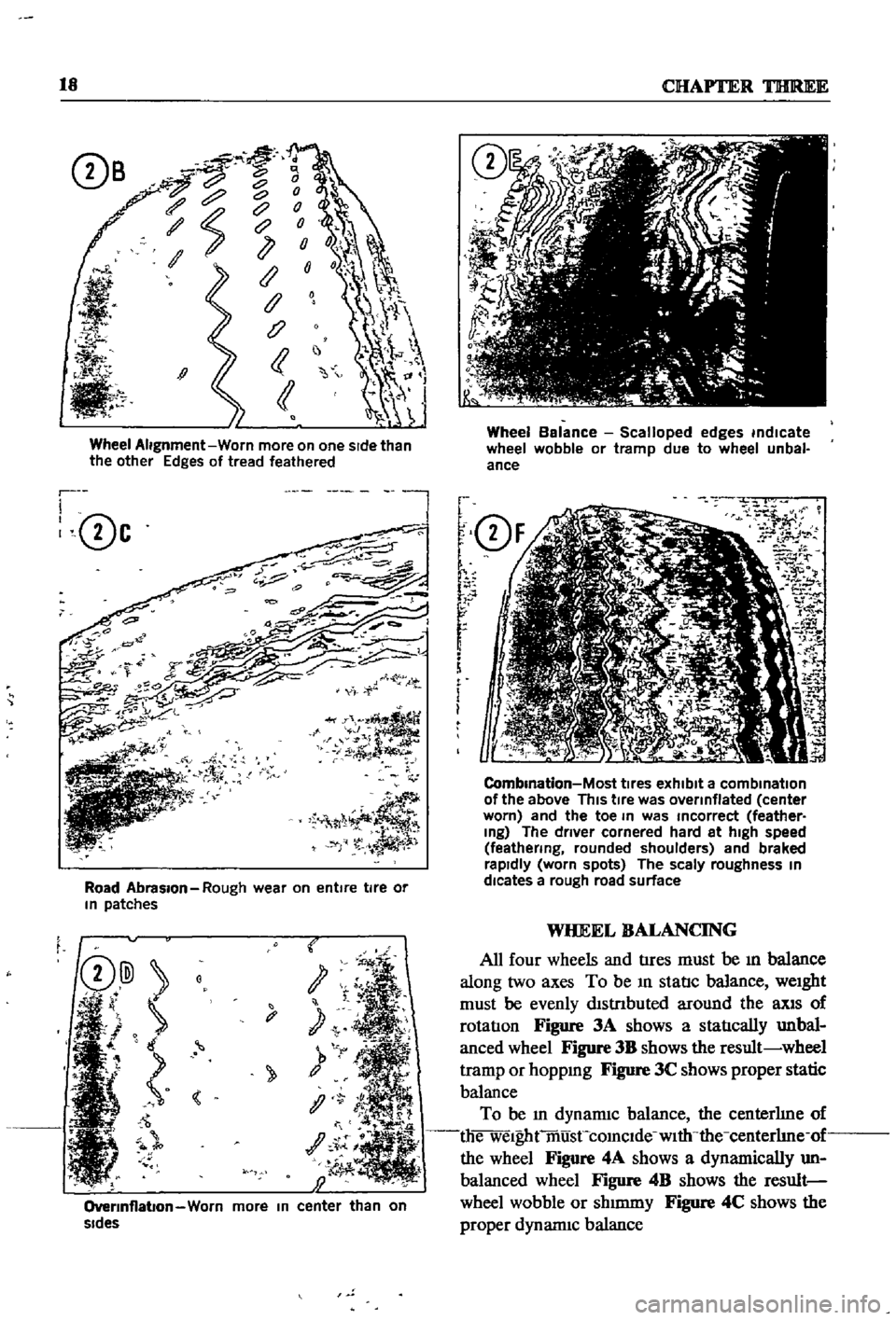
Wheel
Alignment
Worn
more
on
one
sIde
than
the
other
Edges
of
tread
feathered
r
I
0c
l
Road
Abrasion
Rough
wear
on
entire
tire
or
In
patches
t
y
1
OverInflabon
Worn
more
In
center
than
on
sides
Wheel
Balance
Scalloped
edges
indicate
wheel
wobble
or
tramp
due
to
wheel
unbal
ance
f
Q
F
r
r
r
f
i
m
i
O
2
7
iK
J
1
J
i
i
5J
CombInation
Most
tIres
exhibit
a
combination
of
the
above
This
tIre
was
overinflated
center
worn
and
the
toe
In
was
Incorrect
feather
Ing
The
driver
cornered
hard
at
high
speed
feathering
rounded
shoulders
and
braked
rapidly
worn
spots
The
scaly
roughness
In
dlcates
a
rough
road
surface
WHEEL
BALANCING
All
four
wheels
and
tIres
must
be
ill
balance
along
two
axes
To
be
ill
statIc
balance
weight
must
be
evenly
dlstnbuted
around
the
llXlS
of
rotatIon
Figure
3A
shows
a
statIcally
unbal
anced
wheel
Figure
3B
shows
the
result
wheel
tramp
or
hoppmg
Figure
3C
shows
proper
static
balance
To
be
ill
dynamiC
balance
the
centerhne
of
die
welghtmusCcomclde
with
the
centerhne
of
the
wheel
Figure
4A
shows
a
dynamically
un
balanced
wheel
Figure
4B
shows
the
result
wheel
wobble
or
shmuny
Figure
4C
shows
the
proper
dynannc
balance
Page 49 of 252
44
CHAPTER
SIX
@
@
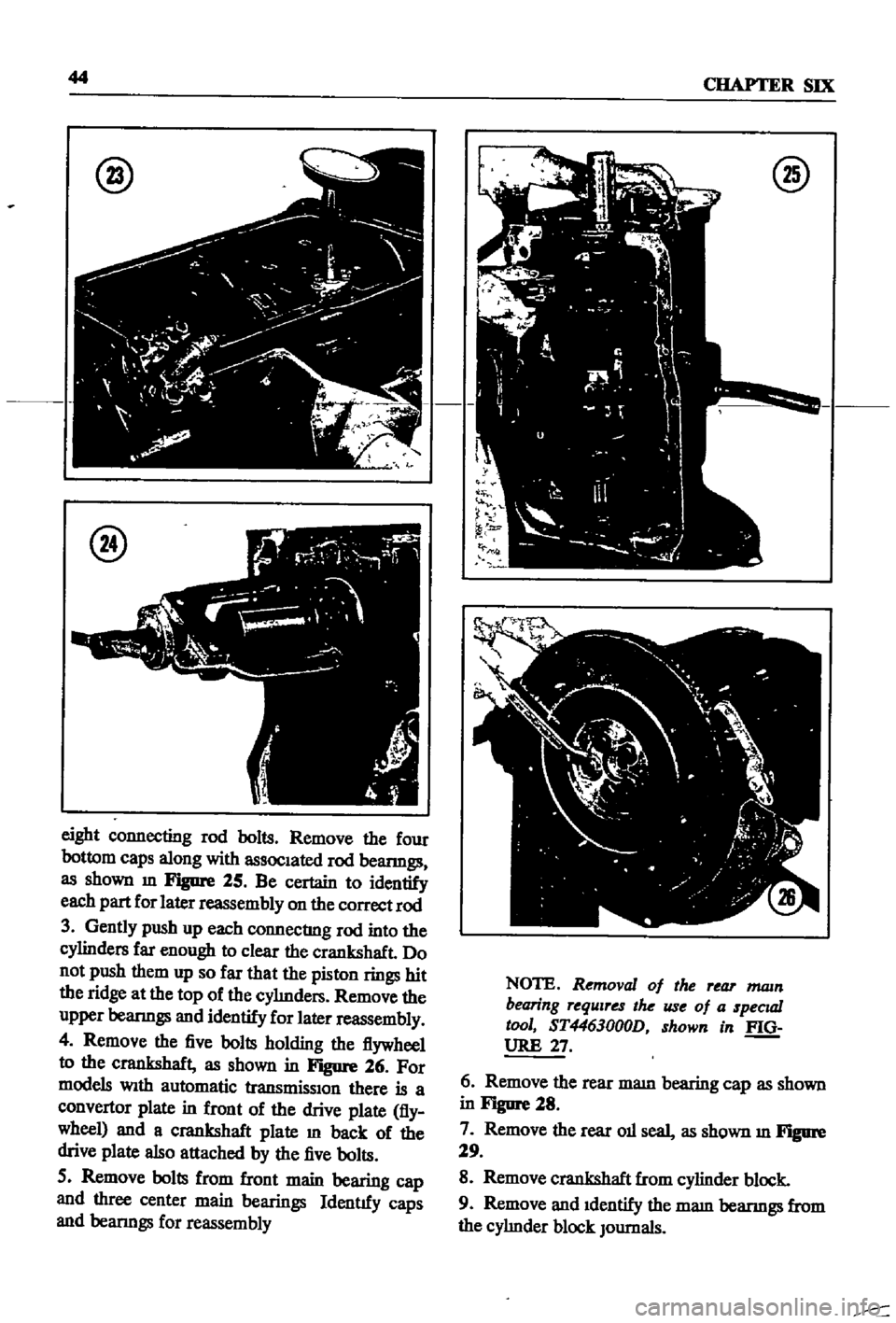
eight
connecting
rod
bolts
Remove
the
four
bottom
caps
along
with
assoc1ated
rod
beanngs
as
shown
m
Figure
25
Be
certain
to
identify
each
part
for
later
reassembly
on
the
correct
rod
3
Gently
push
up
each
connecting
rod
into
the
cylinders
far
enough
to
clear
the
crankshaft
Do
not
push
them
up
so
far
that
the
piston
rings
hit
the
ridge
at
the
top
of
the
cyImders
Remove
the
upper
beanngs
and
identify
for
later
reassembly
4
Remove
the
five
bolts
holding
the
flywheel
to
the
crankshaft
as
shown
in
Figure
26
For
models
Wlth
automatic
transmisslOn
there
is
a
convertor
plate
in
front
of
the
drive
plate
fly
wheel
and
a
crankshaft
plate
m
back
of
the
drive
plate
also
attached
by
the
five
bolts
5
Remove
bolts
from
front
main
bearing
cap
and
three
center
main
bearings
Identtfy
caps
and
beanngs
for
reassembly
@
NOTE
Removal
of
the
rear
mam
bearing
requires
the
use
of
a
specuzl
tool
ST4463000D
shown
in
f
Q
URE
27
6
Remove
the
rear
mam
bearing
cap
as
shown
in
Figure
28
7
Remove
the
rear
011
seal
as
shown
m
Figure
29
8
Remove
crankshaft
from
cylinder
block
9
Remove
and
1dentify
the
mam
beanngs
from
the
cyhnder
block
JOurnals
Page 141 of 252
136
CHAPTER
ELEVEN
5
DIsconnect
and
remove
starter
motor
from
flywheel
housmg
as
descnbe4
In
Chapter
NIne
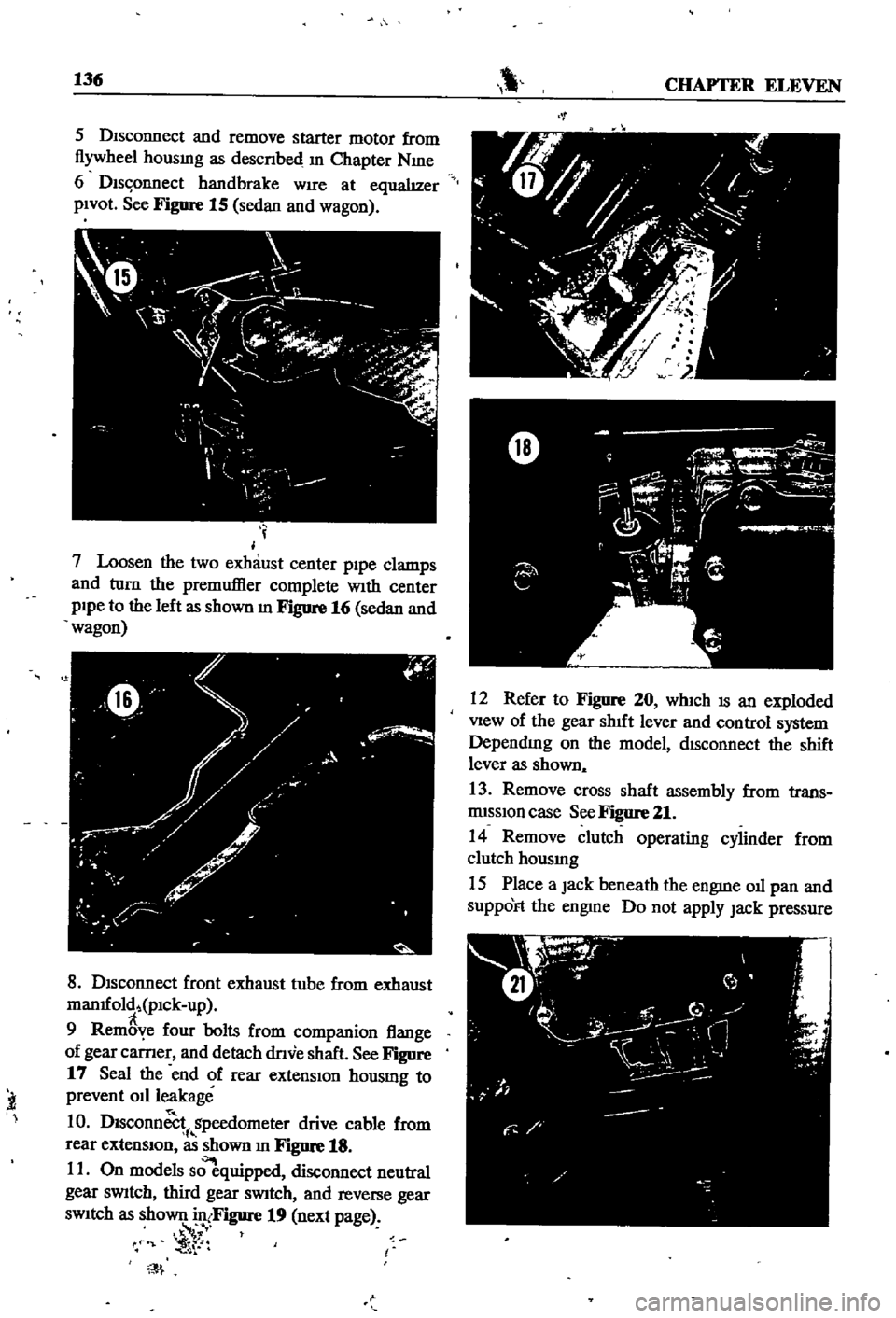
6
Dls
onnect
handbrake
WIre
at
equalIzer
pIVOt
See
Figure
15
sedan
and
wagon
I
j
7
Loosen
the
two
exhaust
center
p1pe
clamps
and
turn
the
premuffier
complete
With
center
pIpe
to
the
left
as
shown
m
FJgure
16
sedan
and
wagon
f
W
y
I
0
Y
h
0
ilo
8
DIsconnect
front
exhaust
tube
from
exhaust
man1fold
pICk
up
9
Rem
ye
four
bolts
from
companion
flange
of
gear
carner
and
detach
dnve
shaft
See
Figure
17
Seal
the
end
of
rear
extensIon
housmg
to
prevent
011
leakage
1
0
Dlsconn
i
gpeedometer
drive
cable
from
rear
extensIOn
as
shown
In
Figure
18
11
On
models
s
quipped
disconnect
neutral
gear
sWitch
third
gear
sWitch
and
reverse
gear
sWItch
as
shown
in
Figure
19
next
page
f
t
iT
l
t
t
W
12
Refer
to
Figure
20
whIch
IS
an
exploded
View
of
the
gear
shIft
lever
and
control
system
DependIng
on
the
model
dISconnect
the
shift
lever
as
shown
13
Remove
cross
shaft
assembly
from
trans
rmsslOn
case
See
Figure
21
14
Remove
clutch
operating
cylinder
from
clutch
housmg
15
Place
a
Jack
beneath
the
engme
011
pan
and
SuppOFt
the
engme
Do
not
apply
Jack
pressure
Page 151 of 252
146
CHAPTER
ELEVEN
o
i
fij@
0
@
7
B@
I
l
I
L
J
1
Before
disassembly
clean
all
parts
and
mark
locations
2
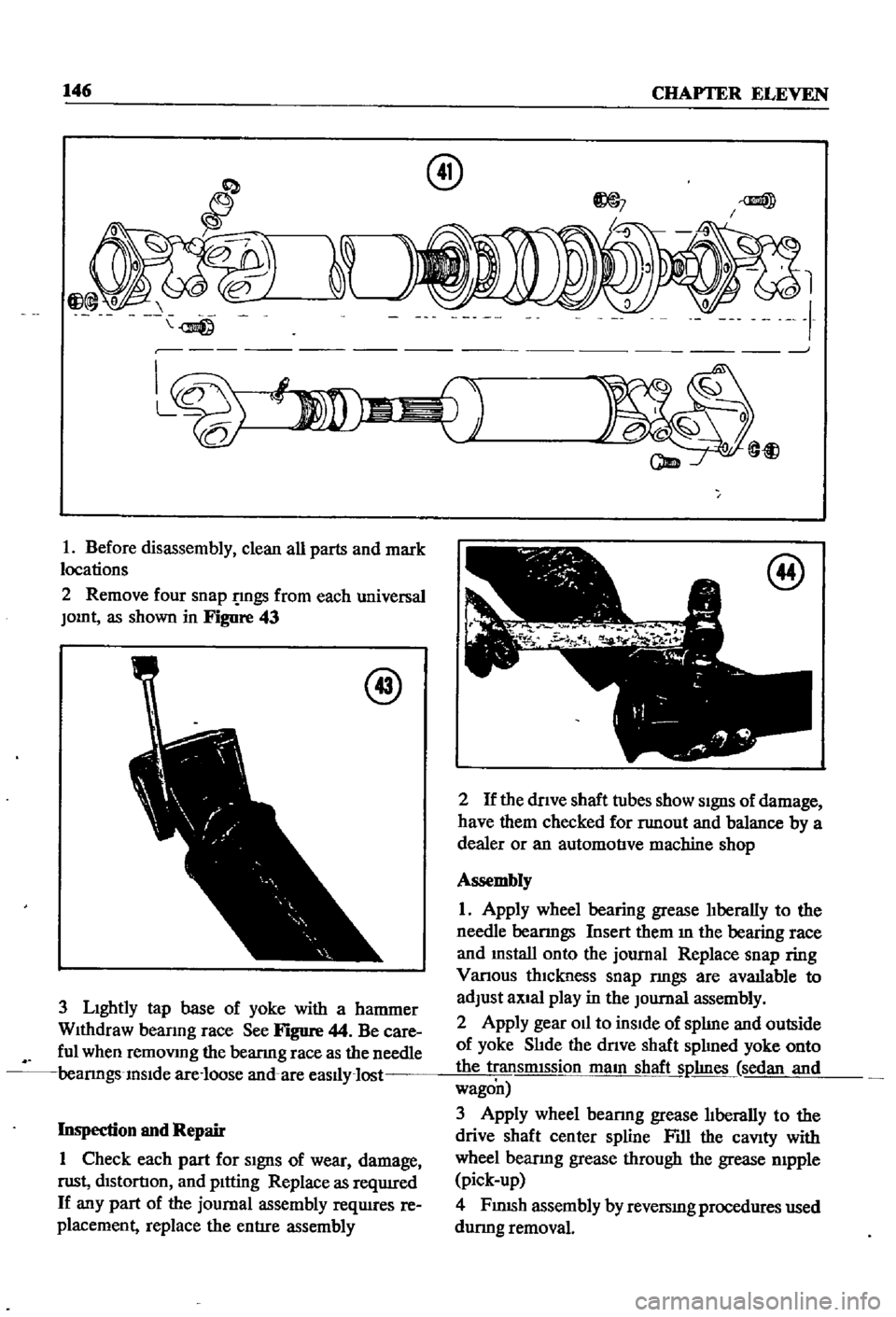
Remove
four
snap
gs
from
each
universal
JOInt
as
shown
in
Figure
43
@
3
LIghtly
tap
base
of
yoke
with
a
hammer
WIthdraw
beanng
race
See
Figure
44
Be
care
ful
when
remoVIng
the
bearmg
race
as
the
needle
bearmgs
InSIde
are
loose
and
are
easlly
lost
Inspection
and
Repair
1
Check
each
part
for
SIgnS
of
wear
damage
nlSt
dIStortIOn
and
pItting
Replace
as
reqUIred
If
any
part
of
the
journal
assembly
reqUIres
re
placement
replace
the
entIre
assembly
am
@
t
@
2
If
the
dnve
shaft
tubes
show
SIgnS
of
damage
have
them
checked
for
nmout
and
balance
by
a
dealer
or
an
automotIve
machine
shop
Assembly
1
Apply
wheel
bearing
grease
lIberally
to
the
needle
bearmgs
Insert
them
m
the
bearing
face
and
mstall
onto
the
journal
Replace
snap
ring
Vanous
thIckness
snap
nngs
are
avatlable
to
adjust
aXIal
play
in
the
Journal
assembly
2
Apply
gear
Oil
to
inSIde
of
splIne
and
outside
of
yoke
SlIde
the
dnve
shaft
splIned
yoke
onto
the
transmIssion
maIn
shaft
Sl1hnes
sedan
and
wagon
3
Apply
wheel
bearmg
grease
lIberally
to
the
drive
shaft
center
spline
Fill
the
caVIty
with
wheel
bearmg
grease
through
the
grease
mpple
pick
up
4
FJ
nlSh
assembly
by
reversIng
procedures
used
durmg
removal
Page 156 of 252

DIFFERENTIAL
REAR
AXLE
AND
REAR
SUSPENSION
151
4
Lower
the
Jack
and
r
move
dIfferentIal
from
rear
of
vehIcle
See
Figure
4
After
removal
sup
port
suspensIon
member
wIth
a
stand
to
prevent
distortlon
and
damage
to
the
Insulators
Differential
Inspection
Sedan
The
followmg
mspectIon
can
be
done
WIthout
disassembly
of
the
dIfferential
If
abnormalitIes
or
damage
eXiSts
refer
further
servIce
and
reparr
to
your
dealer
1
Check
the
tooth
contact
pattern
With
lead
oXide
at
two
or
three
pomts
after
removmg
rear
cover
Refer
to
Figure
5
which
shows
the
cor
rect
contact
pattern
If
the
contact
pattern
IS
m
correct
dIsassembly
and
adjustment
of
dIffer
entlalls
reqUIred
CD
TOE
HEEL
DRIVE
SIDE
HEEL
COAST
SIDE
2
Use
a
dIal
mdtcator
to
measure
backlash
be
tween
the
dnve
gear
and
pmIOn
Backlash
should
be
0
0039
to
0
0079
m
0
10
to
o
20mm
Check
all
gear
teeth
for
damage
and
cracks
3
Check
runout
at
the
rear
of
the
dnve
gear
If
the
tooth
contact
pattern
or
backlash
IS
ab
normal
Runout
should
be
less
than
00031
m
0
08mm
See
Figure
6
4
Rotate
the
gears
and
lIsten
for
SignS
of
de
fective
bearmgs
If
noises
are
eVIdent
the
dIf
ferential
must
be
dIsassembled
and
repaired
CD
Diflerentiallnstallation
Sedan
1
Mount
the
dIfferentIal
assembly
to
the
rear
suspensIOn
member
2
FIt
the
dIfferentIal
mountlng
member
to
the
fittmg
hole
by
pushIng
It
forward
with
a
bar
Torque
the
nuts
to
61
ft
lb
8
5
kg
m
3
Install
axle
dnve
shafts
dnve
shaft
and
handbrake
rear
cable
REAR
AXLE
AND
SUSPENSION
SEDAN
Figure
7
and
Figure
8
page
153
are
ex
ploded
dIagrams
of
the
sedan
rear
axle
and
suspensIOn
The
fully
independent
rear
suspen
SIon
IS
a
semI
traIlIng
arm
deSIgn
With
a
sus
penSIOn
member
suspensIOn
arms
coIl
spnngs
and
hydraulIc
shock
absorbers
The
wheel
bearings
are
lIfetime
lubncated
Rear
Axle
and
Suspension
Removal
Sedan
1
Jack
up
the
rear
of
the
veh1cle
and
support
It
on
stands
2
Remove
wheels
3
Refer
to
Figure
9
and
dtsconnect
handbrake
lInkage
and
rerum
sprmg
Remove
tall
pIpe
and
muffler
4
DISconnect
brake
hose
from
brake
tube
Re
move
four
bolts
holdmg
dnve
shaft
to
dIf
ferential
Lower
dnve
shaft
gently
to
ground
Page 177 of 252
17
CHAPTER
THIRTEEN
CD
7
Remove
bearing
collar
and
extract
the
outer
beanng
cage
8
Use
a
screwdriver
to
remove
front
hub
grease
seal
and
imIer
bearmg
cage
9
Use
a
dnft
to
punch
out
the
outer
and
mner
race
of
the
outer
bearmgs
Punch
out
imIer
bearing
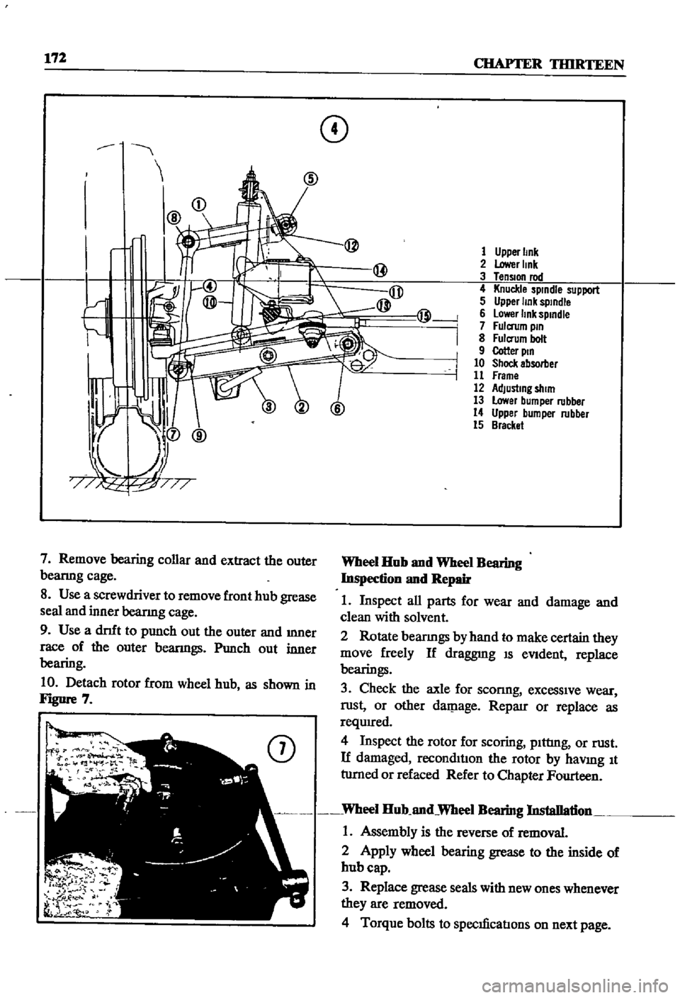
10
Detach
rotor
from
wheel
hub
as
shown
in
FJgUre
7
@
1
Upper
Imk
2
Lower
Imk
3
TenSIOn
rod
4
Knuckle
spindle
support
5
Upper
link
sptndle
6
lower
link
spmdle
7
Fulcrum
pm
8
Fulcrum
bolt
9
Cotter
ptn
10
Shock
absorber
11
Frame
12
AdJustmg
shim
13
Lower
bumper
rubber
14
Upper
bumper
rubber
15
Bracket
Wheel
Hub
nnd
Wheel
Bearing
Inspection
nnd
Repair
1
Inspect
all
parts
for
wear
and
damage
and
clean
with
solvent
2
Rotate
bearmgs
by
hand
to
make
certain
they
move
freely
If
draggnIg
IS
eVident
replace
bearings
3
Check
the
axle
for
sconng
excessive
wear
rust
or
other
daJP
age
Reparr
or
replace
as
requIred
4
Inspect
the
rotor
for
scoring
pIttIng
or
rust
If
damaged
reconditIon
the
rotor
by
haVlDg
It
tumed
or
refaced
Refer
to
Chapter
Fourteen
Wheel
Hub
nnd
Wheel
Bearing
Installation
1
Assembly
is
the
reverse
of
removal
2
Apply
wheel
bearing
grease
to
the
inside
of
hub
cap
3
Replace
grease
seals
with
new
ones
whenever
they
are
removed
4
Torque
bolts
to
specIficatIons
on
next
page