1968 DATSUN 510 charging
[x] Cancel search: chargingPage 3 of 252

CON1EN1S
CHAPTER
ONE
GENERAL
INFORMATION
Introduction
Model
Identification
CHAPTER
TWO
PERIODIC
MAINTENANCE
RoutIne
checks
Pen
odic
checks
CHAPTER
THREE
TROUBLESHOOTING
EqUIpment
Starter
ChargIng
system
EngIne
Igmtlon
system
Fuel
system
Exhaust
emIssIon
control
CHAPTER
FOUR
ENGINE
AND
IGNITION
TUNE
UP
EqUIpment
Battery
Spark
plugs
DIstrIbutor
Igmtlon
timIng
CHAPTER
FIVE
ENGINE
LUBRICATION
SYSTEM
Descnptlon
Lubncation
cIrcuIt
SpecIficatiOns
and
dImensIons
EngIne
lubncation
and
maIntenance
Recommended
lubncants
Clutch
TransmIssiOn
Brakes
Steenng
and
suspension
TIre
wear
analysIs
Wheel
balancIng
Idle
speed
and
Idle
mIXture
Dwell
angle
setting
CompressIon
test
Valve
clearance
adjustment
AddlllOnal
checks
Oil
pump
I
6
t
1
4
V
9
t
1
20
27
Page 4 of 252

II
CHAPTER
SIX
ENGINE
Cylmder
block
Crankshaft
PistOns
and
connectmg
rods
Cyhnder
head
Camshaft
Valve
mechamsm
Camshaft
dnve
Mamfolds
011
pump
Fuel
pump
Carburetor
Emission
control
devIces
Engme
removal
Engme
dISassembly
Pistons
and
connectmg
rods
Cyhnder
head
Engme
mspectIon
and
replllr
Engme
reassembly
Service
data
and
speCifications
CHAPTER
SEVEN
FUEL
SYSTEM
Air
cleaner
Fuel
strlllner
Fuel
pump
Carburetor
Fuel
tank
1
CHAPTER
EIGHT
COOLING
SYSTEM
DescnptIon
Water
pump
Fan
clutch
Thermostat
Radiator
CHAPTER
NINE
ENGINE
ELECTRICAL
SYSTEM
Starter
Overrunmng
clutch
assembly
ChargIng
ClrcUlt
Alternator
Alternator
output
Voltage
regulator
DIstrIbutor
Condenser
Igrntlon
cod
SpeCifications
Spark
plugs
CHAPTER
TEN
EMISSION
CONTROL
SYSTEM
Exhaust
emiSSIOn
control
Crankcase
emission
control
Air
mJectlon
system
Engme
modifications
Evaporative
emiSSion
control
Exhaust
system
CHAPTER
ELEVEN
CLUTCH
TRANSMISSION
AND
DRIVESHAFT
Clutch
TransmissIon
Master
cyhnder
TransmissIon
data
and
speCIfications
Operating
cyhnder
Dnveshaft
Withdrawal
lever
adjustment
Dnveshaft
data
and
speCIfications
Clutch
system
bleedmg
Automatic
transmIssIon
checks
Clutch
data
and
speCIfications
31
62
84
91
114
127
Page 17 of 252

12
CHAPTER
THREE
13
IMPROPER
IDLE
MIXTURE
Roats
slowly
between
13
17
14
SMALl
SPARK
GAP
or
DEFECTIVE
POINTS
Slight
float
between
14
16
ignItIOn
switch
If
the
starter
still
fails
to
crank
properly
remove
the
starter
and
test
it
2
Starter
turns
but
does
not
engage
with
engine
This
trouble
is
usually
a
defective
pInion
or
sole
noid
shlfting
fork
It
may
also
be
that
the
teeth
on
the
pInion
flywheel
ring
gear
or
both
are
worn
down
too
far
to
engage
properly
3
Starter
engages
but
will
not
dISengage
when
IgmtlOn
switch
IS
released
TIns
trouble
is
usually
caused
by
a
sticking
sole
nOid
but
occasionally
the
pmlOn
can
jam
on
the
flywheel
With
manual
transmissions
the
pinion
can
be
temporanly
freed
by
rockmg
the
car
in
high
gear
Naturally
this
IS
not
poSSible
in
auto
matics
the
starter
must
be
removed
4
Loud
grinding
noISes
when
starter
runs
TIns
usually
means
the
teeth
on
the
pinion
and
or
flywheel
are
not
meshing
properly
It
may
also
mean
the
over
running
clutch
IS
broken
In
the
first
case
remove
the
starter
and
examine
the
gear
teeth
In
the
latter
remove
the
starter
and
replace
the
pmion
dnve
assembly
CHARGING
SYSTEM
Charging
system
troubles
may
be
in
the
alter
nator
voltage
regulator
or
fan
belt
The
follow
ing
symptoms
are
typical
1
Alternator
warning
lamp
does
not
come
on
when
IgmtlOn
is
turned
on
This
may
indicate
a
defective
ignition
switch
battery
voltage
regulator
or
lamp
Frrst
try
to
15
HEAD
GASKET
LEAK
Roats
between
5
19
16
RESTRICTm
EXHAUST
SYSTEM
Normal
when
first
started
Drops
to
0
as
rpm
Increases
May
eventually
rrse
to
about
16
start
the
car
If
it
doesn
t
start
check
the
igllltlon
sWitch
and
battery
If
the
car
starts
find
the
voltage
regulator
and
disconnect
the
wlute
red
Wire
this
is
the
lamp
wire
Ground
the
wire
If
the
lamp
hghts
the
voltage
regulator
is
defective
not
properly
grounded
try
tightening
the
mounting
screws
or
the
alternator
brushes
are
not
contactmg
the
commutator
If
the
lamp
does
not
light
when
the
wire
IS
grounded
the
lamp
is
probably
burned
out
replace
It
2
Alternator
warning
lamp
comes
on
and
stays
on
This
usually
mdicates
that
no
chargmg
is
takmg
place
Frrst
check
the
fan
belt
tension
and
adlust
if
necessary
Check
the
battery
condition
with
the
hydrometer
and
check
all
electrical
connec
tions
m
the
chargmg
system
Fmally
isolate
the
trouble
to
the
alternator
or
voltage
regulator
3
Alternator
warmng
lamp
flashes
erratically
This
usually
indicates
the
chargmg
system
is
workmg
intermittently
Check
the
fan
belt
ten
sion
and
all
electncal
connections
m
the
charg
ing
system
Check
alternator
brushes
and
cODlh
tlon
of
the
commutator
4
Baltery
reqUires
frequent
additiOns
of
water
or
lamps
require
frequent
replacement
The
alternator
IS
probably
overchargmg
the
bat
tery
The
voltage
regulator
is
probably
faulty
check
it
using
the
procedures
given
in
Chaper
Nme
5
ExceSSive
noISe
from
he
alternator
Check
for
loose
alternator
mountmg
The
Page 103 of 252

98
CHAPTER
NINE
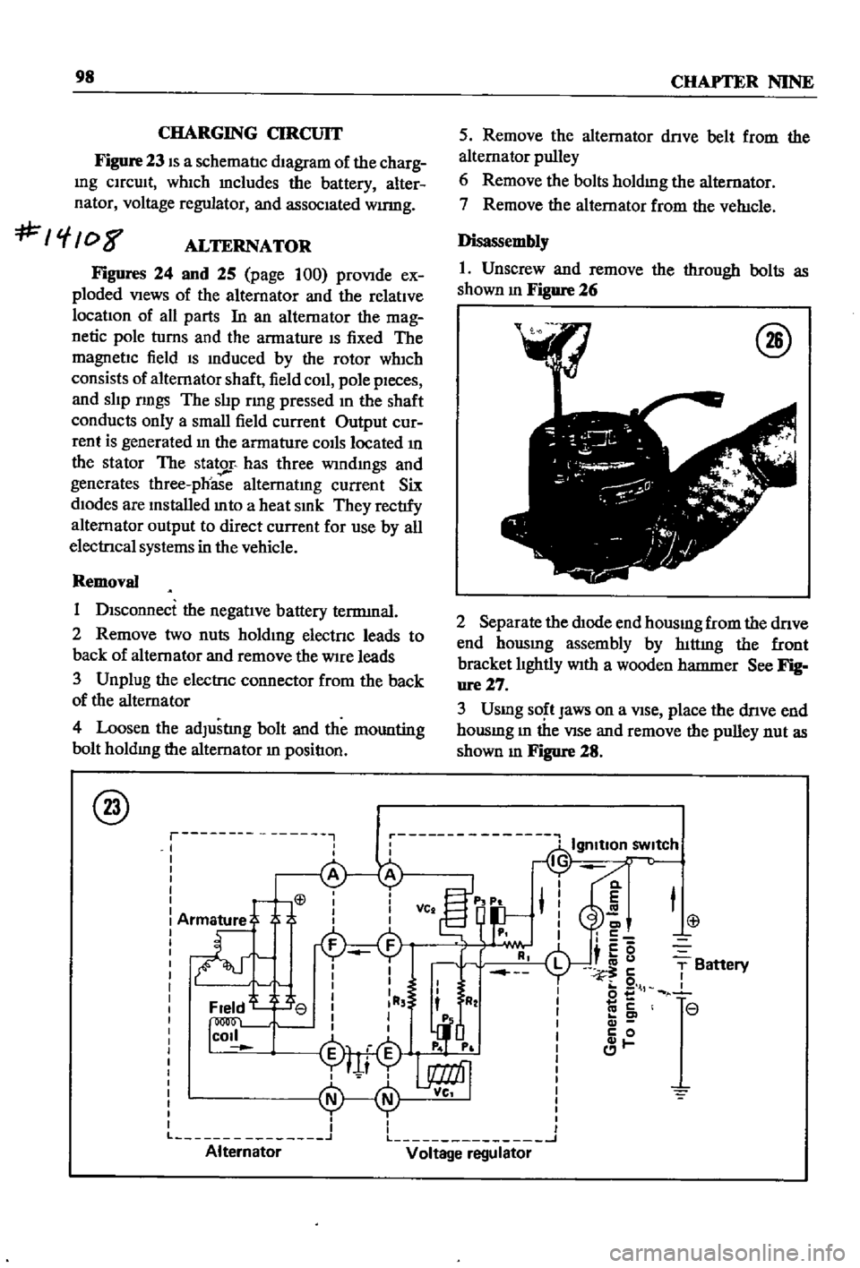
CHARGING
CIRCUIT
Figure
23
IS
a
schematIc
dIagram
of
the
charg
Ing
CIrcuIt
whIch
mcludes
the
battery
alter
nator
voltage
regulator
and
assocIated
wumg
f
08
ALTERNATOR
Figures
24
and
25
page
100
proVIde
ex
ploded
VIews
of
the
alternator
and
the
relatIve
locatIon
of
all
parts
In
an
alternator
the
mag
netic
pole
turns
and
the
armature
IS
fixed
The
magnetIc
field
IS
Induced
by
the
rotor
wh1ch
consists
of
alternator
shaft
field
coIl
pole
pIeces
and
slIp
nngs
The
slIp
rmg
pressed
In
the
shaft
conducts
only
a
small
field
current
Output
cur
rent
is
generated
In
the
armature
COIls
located
In
the
stator
The
stator
has
three
wIndmgs
and
generates
three
phoase
alternatIng
current
Six
dIodes
are
Installed
mto
a
heat
SInk
They
rectIfy
alternator
output
to
direct
current
for
use
by
all
electrIcal
systems
in
the
vehicle
Removal
1
DIsconnect
the
negatIve
battery
terrmnal
2
Remove
two
nuts
holdIng
electnc
leads
to
back
of
alternator
and
remove
the
Wire
leads
3
Unplug
the
electrIc
connector
from
the
back
of
the
alternator
4
Loosen
the
adJustlng
bolt
and
the
mounting
bolt
holdIng
the
alternator
In
positIon
@
r
I
I
I
L
Alternator
5
Remove
the
alternator
dnve
belt
from
the
alternator
pulley
6
Remove
the
bolts
holdmg
the
alternator
7
Remove
the
alternator
from
the
veh1cle
Disassembly
1
Unscrew
and
remove
the
through
bolts
as
shown
m
Figure
26
@
2
Separate
the
dIOde
end
housmg
from
the
dnve
end
hOUSIng
assembly
by
hlttmg
the
front
bracket
lIghtly
WIth
a
wooden
hatnnler
See
Fig
ure27
3
Usmg
SO
t
Jaws
on
a
VIse
place
the
dnve
end
housmg
m
the
VIse
and
remove
the
pulley
nut
as
shown
m
Figure
28
Cl
E
C
c5
i
u
5
o
l
co
c
c
0
1
T
Battery
r
r
L
J
Voltage
regulator
Page 241 of 252

INDEX
A
Inspection
and
repair
191
Air
cleaner
Pad
replacement
190
Exploded
views
63
64
Piston
seal
replacement
193
Removal
and
replacement
62
Reassembly
and
installation
193
Removal
190
Air
pump
40
Brakes
front
pick
up
Alternator
Brushes
104
Adjustment
201
Diode
103
Exploded
View
195
Disassembly
98
ServiCing
194
SpecdicatIons
194
203
204
Exploded
Views
41
99
Brakes
rear
pick
up
Inspection
and
repair
101
Adjustment
202
Output
checks
104
Exploded
View
195
Reassembly
104
Servicing
194
Removal
40
98
Brakes
rear
sedan
and
wagon
Rotor
102
Adjustment
202
Stator
102
Exploded
view
194
Axle
removal
pick
up
175
Inspection
and
repair
193
Reassembly
194
B
Removal
and
disassembly
193
Breaker
points
110
Ball
JOint
lower
sedan
and
wagon
174
Bumpers
Battery
Exploded
view
front
pick
up
223
Inspecllon
aiii
I
servicing
21
Exploded
View
front
sedan
and
wagon
224
SpeCific
gravity
21
Exploded
view
rear
sedan
230
Body
Exploded
view
rear
wagon
231
Body
Irlm
and
bumpers
223
224
Door
lock
and
regulator
225
C
Doors
225
Hood
lock
control
225
Camshaft
Seats
228
DeSCription
34
Tail
gate
228
Exploded
view
37
Trunk
hd
and
bumper
228
Inspection
48
Brake
pedal
Reassembly
54
Inspection
and
repair
187
Sprocket
53
Installation
188
Tlmmg
chain
57
Removal
187
Carburetor
Brakes
Cleaning
and
inspection
75
Adjustment
201
202
Dash
pot
adjustment
71
Bleeding
196
DesCription
37
69
Brake
pedal
187
Disassembly
71
Front
diSC
sedan
and
wagon
190
193
Exploded
Views
74
75
Front
drum
pick
up
194
Fuel
level
adjustment
69
Handbrake
197
201
Idhng
adjustment
69
Master
cyhnder
188
Interlock
valve
70
Rear
pick
up
194
Reassembly
76
Rear
sedan
and
wagon
193
Removal
40
71
SpeCifications
and
service
data
203
204
Sectional
view
69
Troubleshooting
16
Throttle
valve
70
Wheel
cyhnders
pIck
up
196
Charging
system
Brakes
front
diSC
sedan
and
wagon
Troubleshooting
12
Adjustment
201
Choke
and
accelerator
Disassembly
191
Disassembly
and
installation
82
Exploded
view
192
Exploded
view
83