1968 DATSUN 510 wheel bolt torque
[x] Cancel search: wheel bolt torquePage 58 of 252

ENGINE
53
the
mam
beanng
cap
and
the
cyhnder
block
beanng
recess
and
tighten
the
cap
bolts
to
the
proper
torque
WIth
a
torque
wrench
Tig
temng
torque
Main
bearings
506
to
57
8
It
Ib
70to80kg
m
195
to
23
9
It
Ib
27
to3
3
kg
m
Rod
beanngs
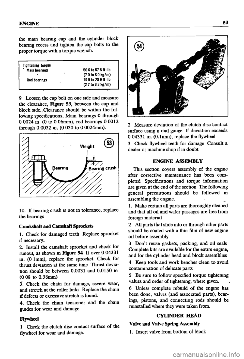
9
Loosen
the
cap
bolt
on
one
Side
and
measure
the
clearance
Figure
53
between
the
cap
and
block
Side
Clearance
should
be
WIthm
the
fol
lowmg
specmcatIons
Mam
beanngs
0
through
o
0024
m
0
to
0
06mm
rod
beanngs
00012
through
0
0032
m
0
030
to
0
0024mm
Weight
@
10
If
beanng
crush
IS
not
m
tolerance
replace
the
beanngs
Crankshaft
and
Camshaft
Sprockets
1
Check
for
damaged
teeth
Replace
sprocket
1f
necessary
2
Install
the
camshaft
sprocket
and
check
for
runout
as
shown
m
Figure
54
If
over
0
04331
m
0
Imm
replace
the
sprocket
Check
for
thrust
deViation
at
the
same
tIme
Thrust
deVia
tIOn
should
be
between
0
0031
and
0
0150
m
008
to
0
38mm
3
Check
the
chain
for
damage
severe
wear
and
stretch
at
the
roller
hnks
Replace
the
cham
1f
defects
or
exceSSIve
stretch
IS
found
4
Check
the
cham
tenslOner
and
the
cham
gwdes
for
wear
and
damage
Flywheel
1
Check
the
clutch
disc
contact
surface
of
the
flywheel
for
wear
and
damage
@
2
Measure
deviation
of
the
clutch
disc
contact
surface
usmg
a
dial
gauge
If
deVIation
exceeds
004331
m
O
lmm
replace
the
flywheel
3
Check
flywheel
teeth
for
damage
Consult
a
dealer
Or
machIne
shop
1f
m
doubt
ENGINE
ASSEMBLY
This
section
covers
assembly
of
the
engme
after
corrective
mamtenance
has
been
com
pleted
SpecificatIons
and
torque
informatIon
are
given
at
the
end
of
the
sectIon
The
followmg
general
precautions
should
be
followed
m
assembhng
the
engme
1
Make
certam
all
parts
are
thoroughly
clean
and
that
all
011
and
water
passages
are
free
from
foreign
matenal
2
All
parts
that
slIde
mto
or
through
other
parts
should
be
coated
With
a
thm
film
of
new
engme
011
before
assembly
3
Don
t
reuse
gaskets
packIng
and
011
seals
Complete
lats
are
aVlUlable
for
the
entire
engme
and
for
the
cyhnder
head
and
block
assemblIes
4
Keep
tools
and
work
benches
clean
to
aVOid
contammatlon
of
delIcate
parts
5
Be
sure
to
follow
specmed
torque
tIghtenmg
values
and
order
of
tlghtenmg
where
given
6
Unless
complete
rebwld
of
the
engme
has
been
done
valves
and
associated
parts
bear
ings
pistons
and
connectIng
rods
should
be
remstalled
where
they
were
taken
from
CYLINDER
HEAD
Valve
and
Valve
Spring
Assembly
1
Insert
valve
from
bottom
of
block
Page 60 of 252

ENGINE
55
Cylinder
Block
Assembly
1
PositIon
all
crankshaft
parts
on
a
work
bench
ThIS
mcludes
the
crankshaft
main
beanngs
rear
011
seal
woodruff
keys
crankshaft
gear
011
pump
gear
011
thrower
bolts
and
bearing
caps
Figure
57
shows
the
arrangement
@
2
Insert
maIO
beanngs
mto
appropnate
cy1m
der
block
holders
NOTE
The
center
No
3
beanng
IS
the
only
flanged
type
of
thrust
bear
Ing
Bearings
No
2
and
No
4
are
Identical
No
1
and
No
5
Jaring
ap
pear
identical
but
No
1
as
an
011
hole
All
bearings
except
No
1
are
Interchangeable
as
to
upper
and
lower
half
3
LIghtly
lubncate
the
crankshaft
and
beanng
matmg
surfaces
then
mstall
beanngs
10
mam
beanng
caps
4
Install
the
crankshaft
5
Install
mam
beanng
caps
over
crankshaft
msert
mam
cap
bolts
and
tighten
hghtly
The
mam
beanng
caps
have
an
arrow
marked
on
each
one
These
must
pomt
to
the
front
of
the
engme
6
Gently
move
the
crankshaft
10
an
aXIal
drrec
don
toward
the
front
of
the
engme
to
venfy
that
the
mam
beanng
caps
are
properly
alIgned
and
seated
7
Use
a
torque
wrench
to
tighten
the
cap
bolts
to
the
hmlts
speCIfied
The
t1ghtenmg
operatIon
should
be
done
gradually
10
three
or
four
sep
arate
stages
starting
10
the
center
and
workmg
outward
to
each
end
8
Rotate
the
crankshaft
to
make
certain
it
isn
t
bmding
9
Use
a
feeler
gauge
to
check
the
end
play
at
the
center
No
3
beanng
Figure
58
10
Install
the
SIde
oll
seals
into
the
rear
mam
cap
and
cy1mder
block
as
shown
10
Figure
59
@
11
Install
the
rear
011
seal
WIth
Datsun
tool
ST49370000
or
equIvalent
12
Install
the
rear
end
plate
13
Install
the
flywheel
WIth
proper
bolts
and
lock
washers
and
torque
as
specified
Page 64 of 252

ENGINE
59
2
Coat
the
pan
gasket
on
both
sides
With
gasket
compound
and
attach
the
oil
pan
to
the
cyhnder
block
Torque
as
specIfied
Manifold
and
Carburetor
Installation
1
Install
the
mtake
and
exhaust
manIfolds
WIth
associated
gasket
to
the
cylmder
head
2
Mount
the
carburetor
and
gasket
to
the
mtake
manIfold
2
Adjust
all
mtake
and
exhaust
valves
to
the
specIfied
clearance
for
a
cold
engme
Clutch
Assembly
Installation
CAUTION
Take
extreme
care
not
to
get
grease
or
011
on
the
clutch
or
flywheel
frlc
hon
contact
surfaces
1
Place
the
clutch
disc
assembly
on
the
flywheel
With
the
longer
chamfered
splmed
end
of
the
dISC
toward
the
transmISSion
2
Visually
align
or
use
a
dummy
splmed
dnve
shaft
to
ahgn
the
diSC
assembly
With
the
flywheel
pilot
beanng
3
Install
and
tighten
the
SIX
bolts
holdmg
the
clutch
cover
assembly
to
the
flywheel
Tighten
the
bolts
a
turn
each
tune
by
diagonal
pattern
until
they
are
tight
Tlghtenmg
torque
should
be
174
to
188ft
lbs
24
to
2
6
kg
m
NOTE
There
are
two
dowels
on
the
flywheel
to
locate
the
clutch
cover
4
Remove
dummy
shaft
If
used
after
the
above
bolts
are
fully
tightened
5
Refit
the
release
bearing
and
translI11Ssion
case
Miscellaneous
Installation
1
Connect
the
fuel
hose
on
the
front
part
of
the
engme
to
the
fuel
pump
and
to
the
carburetor
2
Gap
the
spark
plugs
and
mstall
them
usmg
new
gaskets
3
Coat
the
rocker
arm
cover
gasket
With
sealer
and
position
It
on
the
cylmder
head
4
Install
the
rocker
arm
cover
and
tighten
the
two
thumb
screws
that
hold
it
m
place
5
Install
distrIbutor
makmg
certam
that
the
notch
on
the
distributor
shaft
assembly
mates
With
the
drive
spmdle
Ahgn
the
location
marks
made
dunng
disassembly
so
that
the
distrIbutor
is
positioned
as
before
6
Install
and
tighten
the
bolts
which
hold
the
dIStributor
to
the
front
cover
7
Install
pomts
condenser
and
rotor
8
Replace
distrIbutor
cap
and
attach
spark
plug
Wires
m
the
correct
sequence
Make
certain
that
all
wires
are
firmly
seated
m
the
distrIbutor
cap
and
attached
securely
to
the
spark
plugs
9
HOISt
the
engme
assembly
from
the
work
stand
10
Install
the
alternator
bracket
alternator
and
engme
mounts
to
the
block
11
Install
the
IgnItIon
coil
oil
filter
oil
pressure
SWitch
dipstick
and
water
drain
plug
12
Connect
the
vacuum
Ime
between
the
dis
trIbutor
and
carburetor
13
Connect
the
transIDlSSlOn
to
the
engine
prior
to
mstallatIon
m
the
vehicle
Engine
Installation
Installation
is
the
reverse
of
the
procedures
followed
m
removal
Be
certaIn
thatlall
battery
connections
are
made
that
water
hoses
are
se
cured
wmng
IS
connected
properly
and
that
all
required
bolts
and
mounts
are
mstalled
and
tightened
Replace
the
radiator
fan
belts
and
radiator
shroud
Fill
the
engme
With
the
proper
grade
of
oil
and
the
radiator
With
recommended
coolant
Install
the
hood
to
the
hInges
according
to
the
marks
made
dUrIng
removal
SERVICE
DATA
AND
SPECIFICATIONS
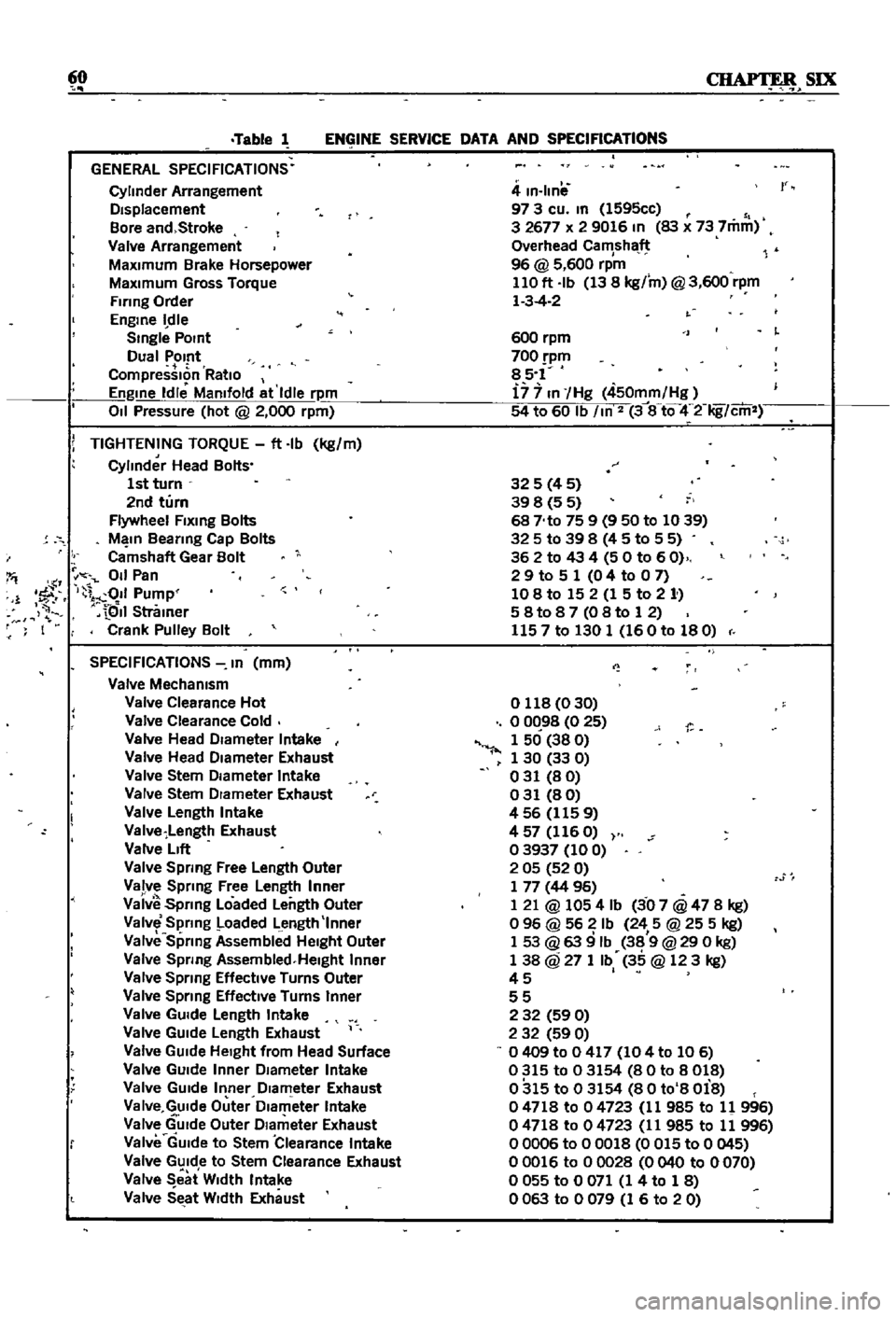
Table
1
covers
servIce
data
and
engme
Speci
fications
Page 65 of 252

60
SIX
Table
1
ENGINE
SERVICE
DATA
AND
SPECIFICATIONS
GENERAL
SPECIFICATIONS
Cylinder
Arrangement
DIsplacement
Bore
and
Stroke
Valve
Arrangement
MaxImum
Brake
Horsepower
MaxImum
Gross
Torque
Firing
Order
Engme
dle
Smgle
POint
Dual
Pomt
CompressIon
RatIo
Engme
Idle
Mamfold
at
Idle
rpm
011
Pressure
hot
@
2
000
rpm
i
TIGHTENING
TORQUE
ft
Ib
kg
m
Cylinder
Head
Bolts
1st
turn
2nd
turn
Flywheel
Flxmg
Bolts
M
In
Beanng
Cap
Bolts
Camshaft
Gear
Bolt
I
011
Pan
1
1
fF
I
011
Pump
QII
Stramer
F
I
Crank
Pulley
Bolt
SPECIFICATIONS
In
mm
Valve
Mechamsm
Valve
Clearance
Hot
Valve
Clearance
Cold
Valve
Head
DIameter
Intake
Valve
Head
DIameter
Exhaust
Valve
Stem
DIameter
Intake
Valve
Stem
DIameter
Exhaust
Valve
Length
Intake
Valve
Length
Exhaust
Valve
LIft
Valve
Spring
Free
Length
Outer
Valve
Sprmg
Free
Length
Inner
Vaiv
Spnng
Loaded
Length
Outer
Valve
Spring
Loaded
Length
Inner
Valve
Sprmg
Assembllld
HeIght
Outer
Valve
Spnng
Assembled
Helght
Inner
Valve
Spnng
Effective
Turns
Outer
Valve
Sprmg
EffectIve
Turns
Inner
Valve
GUIde
Length
Intake
Valve
GUIde
Length
Exhaust
Valve
GUIde
HeIght
from
Head
Surface
Valve
GUIde
Inner
DIameter
Intake
Valve
GUIde
Inner
DIameter
Exhaust
Va
Ive
GUIde
Outer
Dlam
eter
Intake
Valve
GUIde
Outer
DIameter
Exhaust
Valve
GUIde
to
Stem
Clearance
Intake
Valve
GUIde
to
Stem
Clearance
Exhaust
Valve
eat
W
dth
Intake
Valve
SEtat
WIdth
Exhaust
4
m
Ilnil
97
3
cu
m
1595cc
3
2677
x
2
9016
In
83
x
73
7mm
Overhead
Camshaft
96
@
5
600
rpm
110
ft
Ib
13
8
kg
m
@
3
600
rpm
1
3
4
2
r
600
rpm
700
pm
85
1
i7
7
In
Hg
450mm
Hg
54
to
60
Ib
m
2
3
8
tQ
4
2
Iig
cm
325
4
5
39
8
5
5
68
No
75
9
9
50
to
1039
325
to
39
8
4
5
to
5
5
362
to
43
4
50
to
60
2
9
to
5
1
0
4
to
0
7
108
to
15
2
1
5
to
2
1
58t087
08to
12
1157
to
130
1
160
to
180
o
118
0
30
o
0C
98
0
25
1
50
38
0
1
30
33
0
031
80
031
80
456
1159
4
57
116
O
03937
100
2
05
52
0
1
77
44
96
1
21
@
1054
Ib
3
07
@
47
8
kg
o
96
@
56
Ib
24
5
@
25
5
kg
1
53
@
63
9
Ib
38
9
@
29
0
kg
1
38
@
27
1
Ib
35
@
123
kg
45
I
55
2
32
59
0
2
32
59
0
0409
to
0
417
104
to
106
0315
to
03154
80
to
8018
0315
to
03154
80
to
8
Oi8
04718
to
04723
11
985
to
11
996
04718
to
04723
11
985
to
11
996
00006
to
00018
0
015
to
0
045
00016
to
00028
0040
to
0070
o
055
to
0
071
1
4
to
1
8
0063
to
0079
1
6
to
20
Page 134 of 252

CLUTCH
TRANSMISSION
AND
DRIVESHAFI
129
scratches
on
the
pressure
plate
may
be
removed
with
crocus
cloth
If
the
source
of
clutch
trouble
IS
still
not
evl
dent
take
the
pressure
plate
and
disc
to
a
compe
tent
garage
to
check
the
pressure
plate
finger
release
height
and
nmout
Never
attempt
to
ad
just
the
fingers
or
dismantle
the
pressure
plate
Without
proper
tools
and
experience
Check
the
release
bearing
by
holdmg
the
Inner
race
and
rotatmg
the
outer
race
With
hght
pres
sure
applied
If
the
bearing
is
rough
or
noisy
replace
it
CAUTION
Never
clean
the
release
bearing
In
solvent
It
IS
prelubriCflted
at
the
fac
tory
Simply
wipe
with
a
Unt
free
cloth
If
the
release
bearing
shows
any
signs
of
loss
of
lubncant
install
a
new
bearing
Replace
the
sleev
lu
SignS
of
wear
are
evident
Clutch
Reassembly
1
Be
sure
your
hands
are
clean
for
the
initIal
assembly
2
Inspect
the
clutch
facings
pressure
plate
and
flywheel
to
be
sure
they
are
free
from
grease
oil
and
other
foreIgn
material
3
TIghtly
fit
release
bearmg
onto
the
bearing
sleeve
When
beanng
IS
mstalled
turn
bearmg
With
a
finger
to
make
sure
It
operates
smoothly
4
Apply
multI
purpose
grease
to
the
bearmg
sleeve
InSIde
groove
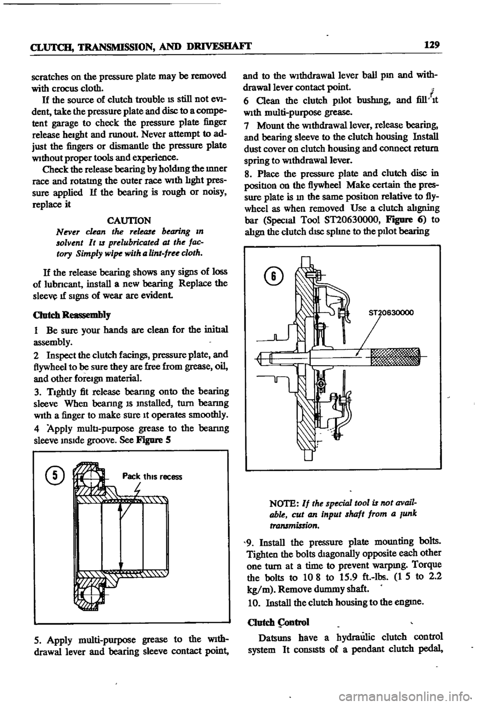
See
Figure
5
CD
Ji
rot
Pac
thiS
r
r
r
1
1i
QI
ecess
5
Apply
multi
purpose
grease
to
the
WIth
drawallever
and
bearing
sleeve
contact
point
and
to
the
Withdrawal
lever
ball
pm
and
with
drawallever
contact
point
f
6
Clean
the
clutch
pllot
bushmg
and
fill
It
With
multi
purpose
grease
7
Mount
the
WithdraWal
lever
release
bearing
and
bearing
sleeve
to
the
clutch
housing
Install
dust
cover
on
clutch
housing
and
connect
return
spring
to
WithdraWal
lever
8
Place
the
pressure
plate
and
clutch
disc
in
positIon
on
the
flywheel
Make
certain
the
pres
sure
plate
is
In
the
same
positIon
relative
to
fly
wheel
as
when
removed
Use
a
clutch
alIgning
bar
Special
Tool
ST20630000
FIgDfe
6
to
alIgn
the
clutch
dISc
splIne
to
the
pllot
bearing
CD
NOTE
If
the
special
tool
is
not
avail
able
cut
an
input
shaft
from
a
Junk
transmission
9
Install
the
pressure
plate
mounting
bolts
Tighten
the
bolts
dIagonally
opposite
each
other
one
turn
at
a
time
to
prevent
warpmg
Torque
the
bolts
to
10
8
to
15
9
ft
lbs
1
5
to
2
2
kg
m
Remove
durmny
shaft
10
Install
the
clutch
housing
to
the
engme
Clutch
ntrol
Datsuns
have
a
hydraulic
clutch
control
system
It
consISts
of
a
pendant
clutch
pedal
Page 139 of 252

134
CHAPTER
ELEVEN
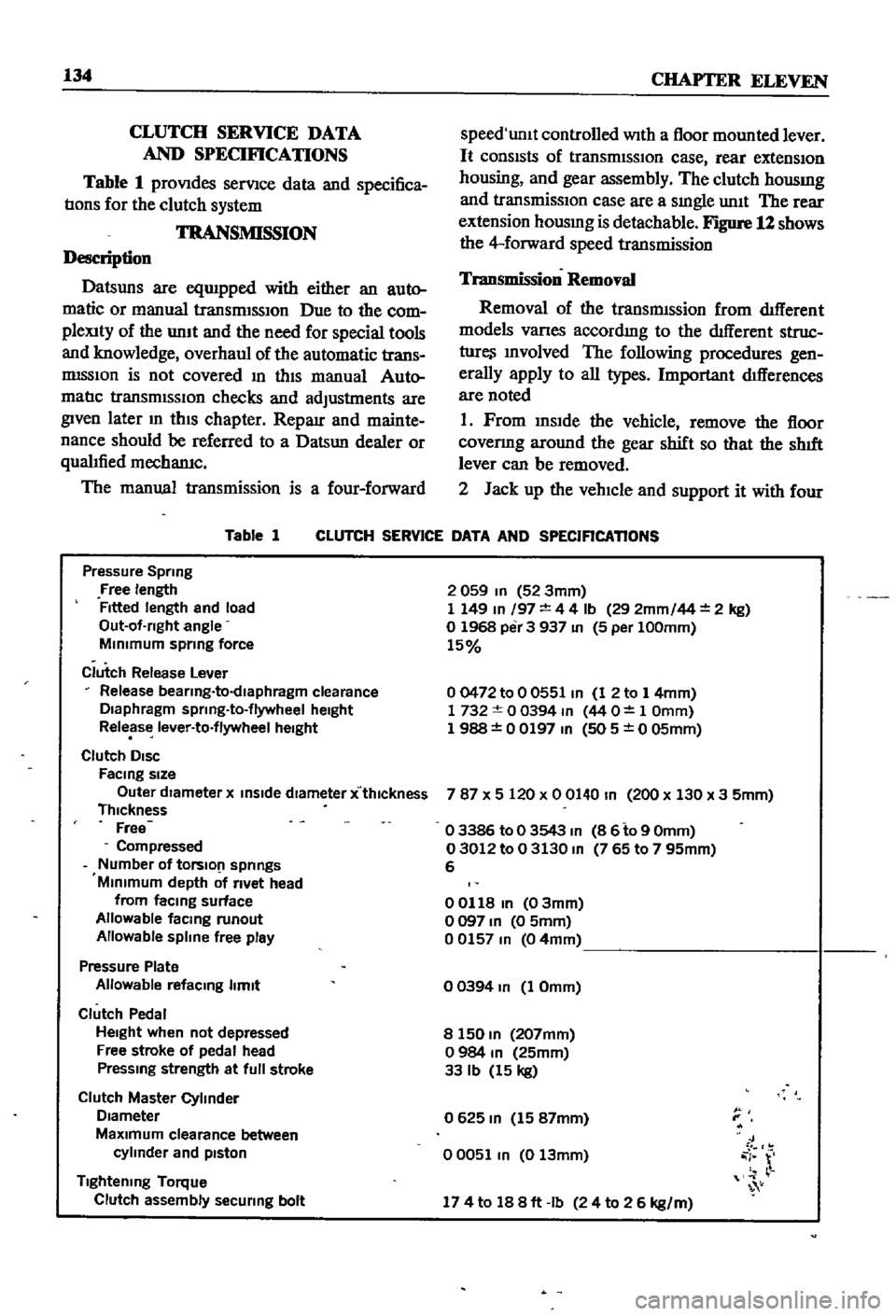
CLUTCH
SERVICE
DATA
AND
SPECIF1CATIONS
Table
1
proVIdes
serVIce
data
and
specifica
tIons
for
the
clutch
system
TRANSMISSION
Description
Datsuns
are
eqUIpped
with
either
an
auto
matic
or
manual
transrmSSIOn
Due
to
the
com
pleXity
of
the
unIt
and
the
need
for
special
tools
and
knowledge
overhaul
of
the
automatic
trans
mISSIon
is
not
covered
In
thIS
manual
Auto
matIc
transmISSIOn
checks
and
adjustments
are
given
later
m
thIS
chapter
Reparr
and
mainte
nance
should
be
referred
to
a
Datsun
dealer
or
qualIfied
mechamc
The
manual
transmission
is
a
four
forward
Table
1
speed
unlt
controlled
With
a
floor
mounted
lever
It
consIsts
of
transrmSSIOn
case
rear
extensIOn
housing
and
gear
assembly
The
clutch
housmg
and
transmissIOn
case
are
a
sIngle
unIt
The
rear
extension
housmg
is
detachable
Figure
12
shows
the
4
forward
speed
transmission
Transmission
Removal
Removal
of
the
transmIssion
from
dIfferent
models
Varles
accordmg
to
the
dIfferent
struc
ture
Involved
The
following
procedures
gen
erally
apply
to
all
types
Important
dIfferences
are
noted
1
Prom
InsIde
the
vehicle
remove
the
floor
covenng
around
the
gear
shift
so
that
the
shIft
lever
can
be
removed
2
Jack
up
the
vehIcle
and
support
it
with
four
CLUTCH
SERVICE
DATA
AND
SPECIFICATIONS
Pressure
Spring
Free
length
Fitted
length
and
load
Out
of
rlght
angle
MInimum
sprmg
force
Clutch
Release
Lever
Release
bearlng
to
dlaphragm
clearance
Diaphragm
sprlng
to
flywheel
height
Release
lever
to
flywheel
height
Clutch
DISC
FaCing
size
Outer
dIameter
x
inSide
diameter
x
thlckness
Thickness
Free
Compressed
Number
of
tOrslO
1
springs
Minimum
depth
of
rivet
head
from
faCing
surface
Allowable
facmg
runout
Allowable
spline
free
play
Pressure
Plate
Allowable
refacmg
limit
Clutch
Pedal
Height
when
not
depressed
Free
stroke
of
pedal
head
Pressmg
strength
at
full
stroke
Clutch
Master
Cylinder
Diameter
MaXimum
clearance
between
cylinder
and
pIston
Tightening
Torque
Clutch
assembly
securing
bolt
2
059
In
52
3mm
1
149
In
197
4
4
Ib
29
2mm
44
2
kg
o
1968
per
3
937
In
5
per
100mm
15
00472
to
0
0551
In
1
2
to
1
4mm
1732
0
0394
m
44
O
1
Omm
1
988
0
0197
In
505
0
05mm
787
X
5
120
x
0
0140
In
200
x
130
x
3
5mm
o
3386
to
0
3543
m
8
6
to
9
Omm
03012
to
0
3130
m
765
to
7
95mm
6
00118
In
03mm
o
097
In
0
5mm
00157
m
04mm
o
0394
In
1
Omm
8
150
m
207mm
o
984
m
25mm
33
Ib
15
kg
0625
m
15
87mm
00051
m
0
13mm
J
i
r
174
to
188ft
Ib
24
to
2
6
kg
m
Page 156 of 252

DIFFERENTIAL
REAR
AXLE
AND
REAR
SUSPENSION
151
4
Lower
the
Jack
and
r
move
dIfferentIal
from
rear
of
vehIcle
See
Figure
4
After
removal
sup
port
suspensIon
member
wIth
a
stand
to
prevent
distortlon
and
damage
to
the
Insulators
Differential
Inspection
Sedan
The
followmg
mspectIon
can
be
done
WIthout
disassembly
of
the
dIfferential
If
abnormalitIes
or
damage
eXiSts
refer
further
servIce
and
reparr
to
your
dealer
1
Check
the
tooth
contact
pattern
With
lead
oXide
at
two
or
three
pomts
after
removmg
rear
cover
Refer
to
Figure
5
which
shows
the
cor
rect
contact
pattern
If
the
contact
pattern
IS
m
correct
dIsassembly
and
adjustment
of
dIffer
entlalls
reqUIred
CD
TOE
HEEL
DRIVE
SIDE
HEEL
COAST
SIDE
2
Use
a
dIal
mdtcator
to
measure
backlash
be
tween
the
dnve
gear
and
pmIOn
Backlash
should
be
0
0039
to
0
0079
m
0
10
to
o
20mm
Check
all
gear
teeth
for
damage
and
cracks
3
Check
runout
at
the
rear
of
the
dnve
gear
If
the
tooth
contact
pattern
or
backlash
IS
ab
normal
Runout
should
be
less
than
00031
m
0
08mm
See
Figure
6
4
Rotate
the
gears
and
lIsten
for
SignS
of
de
fective
bearmgs
If
noises
are
eVIdent
the
dIf
ferential
must
be
dIsassembled
and
repaired
CD
Diflerentiallnstallation
Sedan
1
Mount
the
dIfferentIal
assembly
to
the
rear
suspensIOn
member
2
FIt
the
dIfferentIal
mountlng
member
to
the
fittmg
hole
by
pushIng
It
forward
with
a
bar
Torque
the
nuts
to
61
ft
lb
8
5
kg
m
3
Install
axle
dnve
shafts
dnve
shaft
and
handbrake
rear
cable
REAR
AXLE
AND
SUSPENSION
SEDAN
Figure
7
and
Figure
8
page
153
are
ex
ploded
dIagrams
of
the
sedan
rear
axle
and
suspensIOn
The
fully
independent
rear
suspen
SIon
IS
a
semI
traIlIng
arm
deSIgn
With
a
sus
penSIOn
member
suspensIOn
arms
coIl
spnngs
and
hydraulIc
shock
absorbers
The
wheel
bearings
are
lIfetime
lubncated
Rear
Axle
and
Suspension
Removal
Sedan
1
Jack
up
the
rear
of
the
veh1cle
and
support
It
on
stands
2
Remove
wheels
3
Refer
to
Figure
9
and
dtsconnect
handbrake
lInkage
and
rerum
sprmg
Remove
tall
pIpe
and
muffler
4
DISconnect
brake
hose
from
brake
tube
Re
move
four
bolts
holdmg
dnve
shaft
to
dIf
ferential
Lower
dnve
shaft
gently
to
ground
Page 165 of 252

160
CHAPTER
TWELVE
@
@
@
I
F
7
Remove
ten
nuts
holdmg
the
drlIerentIal
assembly
to
the
axle
case
and
withdraw
the
differential
aSsembly
Rear
Axle
Inspection
Assembly
nnd
Installation
Wagon
1
Check
the
axle
shafts
for
straighmess
cracks
damage
wear
and
chstortion
Replace
1f
de
fectIve
Do
not
attempt
to
heat
axle
to
straJghten
I
it
as
thiS
wlll
weaken
the
axle
and
could
lead
to
more
senous
trouble
2
Clean
all
parts
thoroughly
With
solvent
3
Check
011
seal
hp
for
damage
Replace
as
requrred
4
Check
the
beanngs
for
damage
and
replace
1f
defective
5
Assemble
the
rear
axle
urnt
in
the
reverse
of
disassembly
6
Use
a
new
gasket
between
axle
cases
and
drlIerentIal
7
The
gear
carner
fixmg
nuts
must
be
torqued
m
a
diagonal
pattern
to
prevent
011
leaks
Tighten
to
145
to
159ft
lb
20
to
22
kg
m
8
Install
the
grease
catcher
beanng
spacer
bearmg
and
new
bearing
collar
on
the
axle
shaft
The
beanng
collar
must
be
fitted
using
an
arbor
press
and
4
to
5
tons
of
force
Make
cectam
to
pack
the
wheel
beanng
With
grease
and
msert
the
wheel
beanng
With
the
seal
Side
toward
the
wheel
9
If
the
011
seal
has
been
replaced
take
care
not
to
damage
it
when
mstallmg
the
axle
shaft
assembly
As
a
matter
of
good
practice
replace
the
011
seal
whenever
the
axle
is
disassembled
10
Refer
to
Figure
27
and
grease
the
mdicated
areas
Torque
all
bolts
as
speCified
11
Adjust
the
aXial
end
play
between
the
wheel
beanng
and
the
recess
in
the
axle
tube
with
adjusting
shims
The
end
play
should
be
00118
to
00197
m
03
to
O
5mm
Check
end
play
with
a
dial
gauge
as
shown
in
Figure
28