1968 DATSUN 510 oil filter
[x] Cancel search: oil filterPage 18 of 252

TROUBLESHOOTING
13
trouble
may
also
be
worn
bearings
Remove
the
alternator
and
repair
ENGINE
These
procedures
assume
the
starter
cranks
the
engme
over
normally
If
not
refer
to
Starter
section
m
this
chapter
1
Engme
won
t
start
Could
be
caused
by
the
IgOltlon
or
fuel
problems
First
determine
If
high
voltage
to
spark
plug
occurs
To
do
thiS
dISconnect
one
of
the
spark
plug
wires
Hold
the
exposed
wrre
termlOal
y
to
Y2
lOch
from
ground
any
metal
in
engine
com
partment
With
an
msulated
screwdriver
Crank
the
engme
over
If
sparks
do
not
Jump
to
ground
or
the
sparks
are
very
weak
the
trouble
may
be
10
the
IgnitIOn
system
See
Ignition
System
Trou
bleshootmg
to
further
check
If
sparks
occur
properly
the
trouble
may
be
10
the
fuel
system
See
Fuel
System
Troubleshootmg
2
Engme
misses
steadily
Remove
one
spark
plug
wrre
at
a
tune
and
ground
the
wrre
If
engme
mISs
increases
that
cyhnder
was
work
109
properly
Reconnect
the
wire
and
check
the
others
When
a
wire
IS
dIs
connected
and
engme
miss
remams
the
same
that
cylinder
IS
not
finng
Check
spark
as
descnbed
10
Step
1
If
no
spark
occurs
for
one
cyhnder
only
check
dlStnbutor
cap
wrre
and
spark
plug
If
spark
occurs
prop
erly
check
compressIOn
and
mtake
maOlfold
vacuum
to
ISolate
the
trouble
3
Engme
misses
erratlcally
at
all
speeds
Interrmttent
trouble
can
be
difficult
to
find
It
could
be
ill
the
Ignition
system
exhaust
system
or
fuel
system
Follow
troubleshooting
proce
dures
for
these
systems
carefully
to
isolate
the
trouble
4
Engme
misses
at
Idle
only
Trouble
could
exist
anywhere
ill
IgOltlon
system
Follow
Ignition
TroubleshootlOg
procedure
care
fully
Trouble
could
also
eXist
10
the
carburetor
Idle
crrcult
Check
Idle
mIXture
adjustment
and
check
for
restnctions
m
the
idle
crrcUlt
5
Engme
misses
at
high
speed
only
Problems
could
be
ill
the
fuel
or
IgOltlon
systems
heck
accelerator
pump
operation
fuel
pump
dehvery
fuel
hnes
etc
as
descnbed
under
Fuel
System
Troubleshootillg
Also
check
spark
plugs
and
wrres
6
Low
performance
at
all
speeds
poor
acceleratIOn
Trouble
usually
ill
IgOltlon
or
fuel
system
Check
each
With
the
appropnate
troubleshooting
pro
cedure
7
ExceSSive
fuel
consumptIOn
Could
be
caused
by
a
Wide
variety
of
seemmgly
unrelated
factors
Check
for
clutch
shppage
brake
drag
defective
wheel
beanngs
or
poor
front
end
alignment
Check
IgOltlOn
system
and
fuel
system
8
011
pressure
lamp
does
not
light
when
IgmtlOn
switch
IS
on
Check
the
alternator
warning
lamp
If
it
ISn
t
on
either
go
to
Step
1
Chargmg
System
Trouble
shootlOg
If
only
the
oil
pressure
lamp
IS
off
open
the
englOe
compartment
hd
and
locate
the
oil
pressure
sender
on
the
block
near
the
oil
filter
Make
sure
the
wrre
is
connected
to
the
sender
and
makmg
good
contact
Pull
the
wrre
off
and
ground
it
If
the
lamp
hghts
replace
the
sender
If
the
lamp
does
not
light
replace
the
lamp
9
011
pressure
lamp
lights
or
flickers
when
engme
IS
runmng
Indicates
low
or
complete
loss
of
oil
pressure
Stop
the
englOe
unmedmtely
coast
to
a
stop
With
the
clutch
dISengaged
Tlus
may
simply
be
caused
by
a
low
oil
level
or
an
overheatmg
en
glOe
Check
the
oil
level
and
fan
belt
tensIOn
Check
for
a
shorted
oil
pressure
sender
with
an
ohmmeter
or
a
contlOulty
tester
Remove
and
clean
the
oil
dipstick
and
check
oil
level
and
condition
RepleOlsh
or
replace
the
oil
as
re
qurred
Listen
for
unusual
nOISes
mdlcatmg
dam
aged
beanngs
etc
Do
not
re
start
the
engine
until
you
know
why
the
hght
went
on
and
are
sure
that
the
problem
has
been
corrected
IGNITION
SYSTEM
This
procedure
assumes
the
battery
IS
ill
good
enough
condition
to
crank
the
engme
at
a
normal
rate
Page 27 of 252
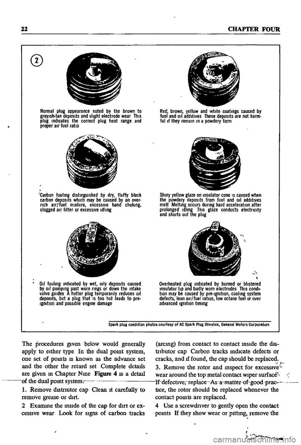
22
CHAPTER
FOUR
CD
Normal
plug
appearance
noted
by
the
brown
to
graYish
tan
deposits
and
slight
electrode
wear
This
plug
rndlcates
the
correct
plug
heat
range
and
proper
air
fuel
ratio
f
j
l
Carbon
fouling
dlstrngUlshed
by
dry
fluffy
black
carbon
deposits
which
may
be
caused
by
an
over
nch
alr
fuel
mixture
excessIVe
hand
chokrng
clogged
air
filter
or
excessive
Idling
lJ
6
1
4i
Z
011
fouling
rndlcated
by
wet
OIly
depOSits
caused
by
011
pumprng
past
worn
rrngs
or
down
the
rntake
valve
gUides
A
hotter
plug
temporanly
reduces
011
depOSits
but
a
plug
that
IS
too
hot
leads
to
pre
IgmtlOn
and
possible
engrne
damage
Red
brown
yellow
and
white
coatrngs
caused
by
fuel
and
011
additives
These
depOSits
are
not
harm
ful
If
they
remarn
rn
a
powdery
form
C
I
Shrny
yellow
glaze
on
rnsulator
cone
IS
caused
when
the
powdery
depOSits
from
fuel
and
011
additives
melt
Meltrng
occurs
dunng
hard
acceleration
after
prolonged
Idling
This
glaze
conducts
electnclty
and
shorts
out
the
plug
Overheated
plug
rndlcated
by
burned
or
blistered
rnsulator
tip
and
badly
worn
electrodes
This
condl
bon
may
be
caused
by
pre
Igmtlon
cooling
system
defects
lean
air
fuel
ratiOS
low
octane
fuel
or
over
advanced
Igmbon
bmrng
Spark
plug
condition
photos
courtesy
of
At
Spark
Plug
DIvision
General
Motors
Corporation
The
procedures
given
below
would
generally
apply
to
eIther
type
In
the
dual
pomt
system
one
set
of
pomts
IS
known
as
the
advance
set
and
the
other
the
retard
set
Complete
details
are
given
m
Chapter
Nme
Figure
4
IS
a
detaIl
of
the
dual
pomt
system
1
Remove
dIStnutor
cap
Clean
It
carefully
to
remove
grease
or
dIrt
2
Examme
the
mSIde
of
the
cap
for
d1rt
or
ex
ceSSIve
wear
Look
for
SIgns
of
carbon
tracks
arcmg
from
contact
to
contact
mSIde
the
dIS
trIbutor
cap
Carbon
tracks
mdlcate
defects
or
cracks
and
If
found
the
cap
should
be
replaced
3
Remove
the
rotor
and
mspect
for
exceSSIve
wear
around
the
top
metal
contact
wiper
surface
If
defectlve
replace
As
a
matter
of
good
prac
nce
the
rotor
should
be
replaced
whenever
the
contact
pomts
are
replaced
4
Use
a
screwdriver
to
gently
open
the
contact
pomts
If
they
show
wear
or
plttmg
remove
the
I
7
r
Page 30 of 252

ENGINE
AND
IGNITION
TUNE
UP
4
25
block
the
throttle
and
choke
m
the
WIde
open
position
3
Remove
all
four
spark
plugs
4
Sequentially
press
a
compressIOn
test
gauge
mto
each
of
the
spark
plug
holes
and
crank
the
engme
for
at
least
four
strokes
Record
the
com
pressIOn
readmg
for
each
cylmder
Standard
compressIOn
readmg
IS
171
Ibs
m
12
0
kg
cm
Mmlmum
acceptable
readmg
IS
159
lbs
m
2
11
5
kg
cm
5
No
readmg
should
be
less
than
80
of
the
highest
cylmder
reading
ExceSSive
vanatiC
ns
between
cylmders
accompanied
by
low
speed
mlssmg
of
the
cyhnder
or
cylmders
that
read
low
usually
mdlcates
a
valve
not
properly
seat
mg
or
a
broken
piston
ring
Low
pressures
even
though
uniform
may
mdicate
worn
nngs
ThIS
IS
especlall
true
1f
ex
cessive
011
cQIlsumptlon
has
been
noticed
If
one
or
more
cylmders
read
low
or
uneven
inject
about
a
tablespoon
of
engine
ail
on
top
of
the
piston
of
that
cylinder
and
crank
the
engine
several
tlmes
noting
the
compressIOn
reading
If
compressIOn
has
nsen
the
piston
nngs
or
cylmders
are
worn
and
should
befserviced
If
compressIOn
has
not
unproved
after
addmg
oil
the
valves
are
Stlcking
or
are
not
seating
prop
erly
If
two
adjacent
cylmders
have
low
compres
sion
and
mjectmg
01
9es
not
increas
the
read
mg
the
head
gasket
between
the
cylmders
IS
probably
leaking
VALVE
CLEARANCE
ADJUSTMENT
Valve
adjustment
should
be
done
in
two
steps
first
With
the
engme
cold
and
then
at
operatmg
temperature
Refer
to
Figure
6
and
proceed
as
follows
1
Remove
arr
liter
2
Remove
rocker
arm
cover
Take
care
not
to
damage
the
gasket
3
Remove
the
spark
plugs
and
rotate
the
en
gine
unt1l
number
1
cylinder
IS
at
top
dead
center
o
l
the
compressIOn
stroke
This
can
be
de
tepnmed
w
hen
the
top
dead
center
mark
on
the
crankshaft
pulley
is
m
alignment
With
the
statIOnary
pomter
and
both
valves
for
number
1
cylmder
are
closed
I
4
Counting
from
the
front
of
the
engme
ad
Just
valves
1
2
3
and
5
as
follows
Loosen
the
pivot
lockmg
nut
and
turn
the
pivot
screw
unt1l
clearance
between
the
pivot
screw
and
the
rock
er
ann
IS
0
0079
m
0
200mm
for
the
mtake
valves
and
0
0098
in
0
25mm
for
the
exhaust
valves
Check
clearances
With
a
feeler
gauge
as
shawn
When
correct
tlghten
the
pivot
locking
nut
l
1
5
Rotate
the
crankshaft
unt1l
the
number
4
pISton
IS
at
top
dead
center
an
the
compressIOn
stroke
This
IS
one
complete
revolution
of
the
crankshaft
Agam
the
0
degree
mark
should
align
With
the
pomter
and
both
valves
on
num
ber
4
cylinder
should
be
closed
6
Adjust
valves
4
6
7
and
8
as
above
i
I
7
Replace
spark
plugs
Ignition
WIres
r
ick
r
1
arm
cover
gasket
and
air
filter
8
Start
engine
and
run
it
unt1l
operating
tem
perature
IS
reached
9
Remove
rocker
ann
cover
and
repeava
iius
ment
Clearances
should
be
0
0098
m
0
25fumj
for
the
mtake
valves
and
00Il8
m
0
30mi
for
the
exhaust
valves
Check
clearances
before
loosening
the
pivot
lockmg
nuts
as
they
may
already
be
properly
set
If
not
adjust
as
re
quir
l
ADDmONAL
CHECKS
l
Qunng
tune
ups
check
the
followmg
Ite
far
SignS
of
defects
or
excessive
wear
I
i
1
Inspect
the
carburetor
for
buildup
of
foreign
matenal
Pay
Special
attention
to
the
throat
and
linkages
Clean
or
overhaul
as
required
Det8
1ls
for
carburetor
mamtenance
are
given
in
Chapter
seven
Page 31 of 252
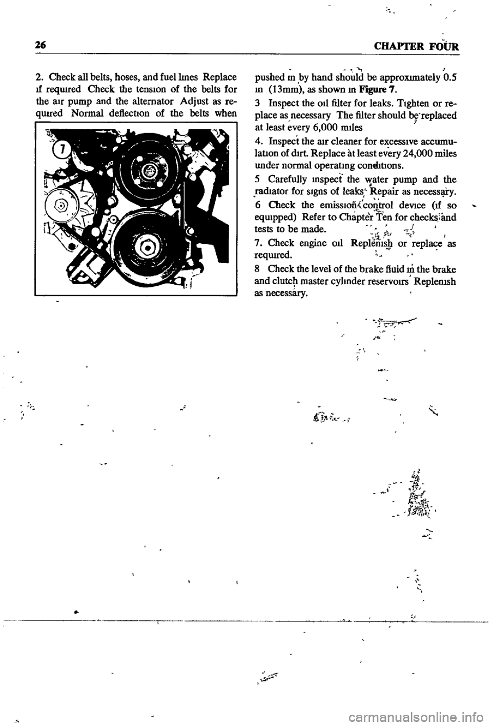
26
CHAPTER
FOUR
2
Check
all
belts
hoses
and
fuellmes
Replace
If
reqUIred
Check
the
tensIon
of
the
belts
for
the
au
pump
and
the
alternator
Adjust
as
re
qUIred
Normal
deflection
of
the
belts
when
pushed
m
by
hand
should
be
approXImately
0
5
m
13mm
as
shown
m
Figure
7
3
Inspect
the
011
filter
for
leaks
TIghten
or
re
place
as
necessary
The
filter
should
replaced
at
least
every
6
000
mIles
4
Inspect
the
lIlr
cleaner
for
excessIve
accumu
latIon
of
dIrt
Replace
at
least
every
24
000
miles
under
normal
operatmg
cornhtIons
5
Carefully
mspect
the
water
pump
and
the
radIator
for
SIgnS
of
leaks
Repair
as
necessl
i
y
6
Check
the
emissIoo
control
deVice
If
so
eqwpped
Refer
to
Chapter
Ten
for
checks
and
tests
to
be
made
c
1
7
Check
engine
oIl
Replems
9
or
replace
as
reqUIred
8
Check
the
level
of
the
brake
fluid
m
the
brake
and
clutcJ1
master
cylmder
reservOirs
ReplenISh
as
necessary
ii
t
d
fl
tlJ
l
Page 35 of 252
30
CHAPTER
FIVE
should
be
1
54
m
39mm
If
the
spnng
tension
is
accurate
the
rehef
valve
should
open
at
54
0
to
59
7
lb
1m
3
8
to
4
2
kg
cm
6
Reassemble
the
oil
pump
Make
certain
all
gaskets
are
mounted
flat
to
avoid
leaks
7
Install
the
dnve
spindle
and
the
oil
pump
to
the
front
cover
8
Install
the
distnbutor
in
the
same
relative
locallon
from
which
it
was
removed
If
the
num
ber
1
cyhnder
was
at
top
dead
center
on
the
compression
stroke
the
punch
mark
on
the
dnve
spindle
should
face
toward
the
front
of
the
engine
9
Install
the
front
splash
shield
and
the
front
stablhzer
10
Insert
the
drain
plug
in
the
pan
and
refill
the
engme
11
Oil
pressure
at
idle
should
be
142
to
17
1
lb
lin
1
0
to
1
2
kg
cm
12
Tlghtenmg
torque
values
for
the
oil
pump
mounting
bolts
is
10
8
to
152ft
lb
1
5
to
2
1
kg
m
and
21
69
to
25
31
ft
lb
3
0
to
25
kg
m
for
the
release
valve
cap
nut
Oil
Filter
The
oil
filter
is
mounted
on
the
nght
hand
side
of
the
cyhnder
block
It
IS
a
cartndge
type
with
built
m
gasket
and
threads
onto
the
mounting
spindle
The
filter
should
be
replaced
every
6
000
miles
as
follows
1
Dram
the
engme
oil
Walt
10
15
minutes
before
removmg
oil
filter
to
allow
It
to
dram
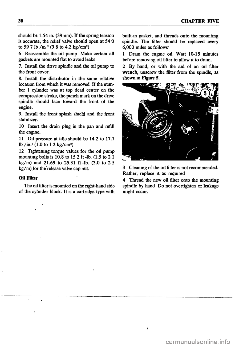
2
By
hand
or
with
the
aid
of
an
oil
filter
wrench
unscrew
the
filter
from
the
spmdle
as
shown
m
Figure
S
3
Cleanmg
of
the
oil
filter
IS
not
recommended
Rather
replace
It
as
reqUIred
4
Thread
the
new
oil
filter
onto
the
mounting
spindle
by
hand
Do
not
overtighten
or
leakage
nught
occur
Page 38 of 252
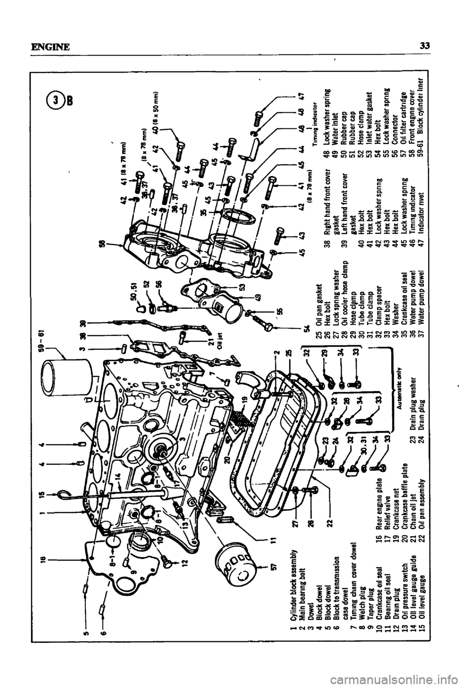
4l
4111a
78
mml
la78mml
42
4
42
4OIla50mml
t
4544
i
35
45
lIq
D
1
43
45
44
6
1i
45
43
42
41
45
44
46
46
47
8
78mml
I
Tlmmg
Indicator
48
lock
washer
spring
49
Water
Inlet
50
Rubber
cap
51
Rubber
cap
52
Hosa
clamp
53
Inlet
watar
gasket
54
Hex
bolt
55
lock
washer
spring
56
Connector
57
011
filter
cartndge
58
front
engme
cover
59
61
Bloel
cyllndelllner
18
15
58
57
1
Cylinder
block
assembly
2
Main
beanng
bolt
3
Dowel
4
Block
dowel
5
Block
dowel
6
Block
to
transmIssIon
case
dowel
7
Tlmmg
chaIn
covar
dowel
8
Welch
plug
9
Taper
plug
10
Crankcase
011
seal
11
Bearing
011
seal
12
Drain
plug
13
011
pressure
sWitch
14
011
level
gauge
guide
15
Oll
evel
gauga
r1
26
54
25
011
pan
gasket
26
Hax
bolt
27
lock
Sprl
ng
washer
28
011
cooler
hose
clamp
29
Hose
cl
mp
30
Tube
clamp
31
Tube
clamp
32
Clamp
spacer
33
Hex
bolt
34
Washer
35
Crankcase
011
seel
36
Waler
pump
dowel
37
Water
pump
dowel
38
RIght
hand
front
caver
gasket
39
left
hand
front
cover
gasket
40
Hex
bolt
41
Hex
bolt
42
lock
washer
spnng
43
Hex
bolt
44
Hex
bolt
45
Lock
washer
spring
46
Tlmmg
Indicator
47
IndIcator
rivet
22
16
23
Drain
plug
washer
24
Dram
plug
e
l
lIlI
1M
1M
Page 64 of 252

ENGINE
59
2
Coat
the
pan
gasket
on
both
sides
With
gasket
compound
and
attach
the
oil
pan
to
the
cyhnder
block
Torque
as
specIfied
Manifold
and
Carburetor
Installation
1
Install
the
mtake
and
exhaust
manIfolds
WIth
associated
gasket
to
the
cylmder
head
2
Mount
the
carburetor
and
gasket
to
the
mtake
manIfold
2
Adjust
all
mtake
and
exhaust
valves
to
the
specIfied
clearance
for
a
cold
engme
Clutch
Assembly
Installation
CAUTION
Take
extreme
care
not
to
get
grease
or
011
on
the
clutch
or
flywheel
frlc
hon
contact
surfaces
1
Place
the
clutch
disc
assembly
on
the
flywheel
With
the
longer
chamfered
splmed
end
of
the
dISC
toward
the
transmISSion
2
Visually
align
or
use
a
dummy
splmed
dnve
shaft
to
ahgn
the
diSC
assembly
With
the
flywheel
pilot
beanng
3
Install
and
tighten
the
SIX
bolts
holdmg
the
clutch
cover
assembly
to
the
flywheel
Tighten
the
bolts
a
turn
each
tune
by
diagonal
pattern
until
they
are
tight
Tlghtenmg
torque
should
be
174
to
188ft
lbs
24
to
2
6
kg
m
NOTE
There
are
two
dowels
on
the
flywheel
to
locate
the
clutch
cover
4
Remove
dummy
shaft
If
used
after
the
above
bolts
are
fully
tightened
5
Refit
the
release
bearing
and
translI11Ssion
case
Miscellaneous
Installation
1
Connect
the
fuel
hose
on
the
front
part
of
the
engme
to
the
fuel
pump
and
to
the
carburetor
2
Gap
the
spark
plugs
and
mstall
them
usmg
new
gaskets
3
Coat
the
rocker
arm
cover
gasket
With
sealer
and
position
It
on
the
cylmder
head
4
Install
the
rocker
arm
cover
and
tighten
the
two
thumb
screws
that
hold
it
m
place
5
Install
distrIbutor
makmg
certam
that
the
notch
on
the
distributor
shaft
assembly
mates
With
the
drive
spmdle
Ahgn
the
location
marks
made
dunng
disassembly
so
that
the
distrIbutor
is
positioned
as
before
6
Install
and
tighten
the
bolts
which
hold
the
dIStributor
to
the
front
cover
7
Install
pomts
condenser
and
rotor
8
Replace
distrIbutor
cap
and
attach
spark
plug
Wires
m
the
correct
sequence
Make
certain
that
all
wires
are
firmly
seated
m
the
distrIbutor
cap
and
attached
securely
to
the
spark
plugs
9
HOISt
the
engme
assembly
from
the
work
stand
10
Install
the
alternator
bracket
alternator
and
engme
mounts
to
the
block
11
Install
the
IgnItIon
coil
oil
filter
oil
pressure
SWitch
dipstick
and
water
drain
plug
12
Connect
the
vacuum
Ime
between
the
dis
trIbutor
and
carburetor
13
Connect
the
transIDlSSlOn
to
the
engine
prior
to
mstallatIon
m
the
vehicle
Engine
Installation
Installation
is
the
reverse
of
the
procedures
followed
m
removal
Be
certaIn
thatlall
battery
connections
are
made
that
water
hoses
are
se
cured
wmng
IS
connected
properly
and
that
all
required
bolts
and
mounts
are
mstalled
and
tightened
Replace
the
radiator
fan
belts
and
radiator
shroud
Fill
the
engme
With
the
proper
grade
of
oil
and
the
radiator
With
recommended
coolant
Install
the
hood
to
the
hInges
according
to
the
marks
made
dUrIng
removal
SERVICE
DATA
AND
SPECIFICATIONS
Table
1
covers
servIce
data
and
engme
Speci
fications
Page 243 of 252
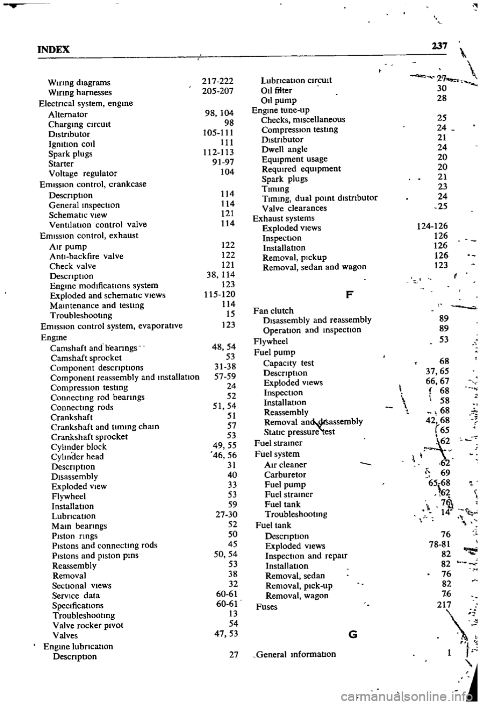
INDEX
237
2
7
30
28
WIrIng
diagrams
WIrIng
harnesses
Electncal
system
engme
Alternator
Chargmg
ClfCUlt
Dlstnbutor
IgmtlOn
coIl
Spark
plugs
Starter
Voltage
regulator
Emission
control
crankcase
DescnptIon
General
mspectIon
SchematIc
vIew
VentIlatIOn
control
valve
EmIssIOn
control
exhaust
AIr
pump
AntI
backfire
valve
Check
valve
DescnptlOn
Engme
modificatIons
system
Exploded
and
schematIc
vIews
Mamtenance
and
testIng
Troubleshootmg
Emission
control
system
evaporatIve
Engme
Camshaft
and
beanngs
Camshaft
sprocket
Component
descnptIons
Componenl
reassembly
and
mstallatIon
CompressIOn
testmg
Connectmg
rod
beanngs
Connectmg
rods
Crankshaft
Crankshaft
and
tImmg
cham
Crankshafl
sprocket
Cylmder
block
CylInder
head
DescnptlOn
Disassembly
Exploded
view
Flywheel
InstallatIOn
LubncatIon
MaIO
bearmgs
PIston
nngs
Pistons
and
connectmg
rods
PiStOns
and
piston
pms
Reassembly
Removal
SectIonal
views
ServIce
data
SpeCificatIons
Troubleshootmg
Valve
rocker
PIvot
Valves
Engme
lubncatlon
DescnptIon
217
222
205
207
98
104
98
105
111
111
112
113
9197
104
122
122
121
38
114
123
115
120
114
15
123
48
54
53
31
38
5759
24
52
51
54
51
57
53
49
55
46
56
31
40
33
53
59
27
30
52
50
45
50
54
53
38
32
60
61
60
61
13
54
47
53
114
114
121
114
LubncatlOn
ClfCUlt
011
filter
011
pump
Engme
tune
up
Checks
miscellaneous
Compression
testIng
DIstributor
Dwell
angle
EqUIpment
usage
ReqUIred
eqUIpment
Spark
plugs
Tlmmg
Tlmmg
dual
pomt
dlstnbutor
Valve
clearances
Exhaust
systems
Exploded
views
InspectIon
InstallatIOn
Removal
pickup
Removal
sedan
and
wagon
F
Fan
clutch
DIsassembly
and
reassembly
OperatIon
and
mspectlon
Flywheel
Fuel
pump
Capacity
test
DescnptlOn
Exploded
views
InspectIOn
InstallatIOn
Reassembly
Removal
an
assembly
StatIc
pressure
test
Fuel
stramer
Fuel
system
Air
cleaner
Carburetor
Fuel
pump
Fuel
stramer
Fuel
tank
Troubleshootmg
Fuel
tank
DescnptIon
Exploded
Views
InspectIOn
and
repaIr
Installation
Removal
sedan
Removal
pick
up
Removal
wagon
Fuses
G
27
General
mformatIon
25
24
21
24
20
20
21
23
24
25
124
126
126
126
126
123
l
89
89
53
68
37
65
66
67
68
58
68
42
68
65
1
2v
62
69
65
68
l
6
7
1
l
76
78
81
82
82
76
82
7
6
2
1
F