1968 DATSUN 510 brake fluid
[x] Cancel search: brake fluidPage 21 of 252
16
CHAPTER
TIlREE
sary
Also
check
all
parts
for
mlSaltgnment
and
uneven
wear
TRANSMISSION
1
Difficult
to
mesh
gears
Make
certam
the
clutch
pressure
plate
and
re
lease
beanng
are
m
good
condItion
The
trouble
can
be
caused
by
worn
gears
shaft
and
or
bear
mgs
DISassemble
and
repaIr
as
requIred
Also
can
be
caused
by
msufficlent
operatmg
stroke
due
to
worn
or
loose
sltdmg
parts
or
a
defective
synchronIZer
DIsassemble
carefully
InSpect
and
replace
as
requIred
2
Gears
slip
out
of
mesh
Generally
thIS
trouble
occurs
when
the
mterlock
plunger
check
ball
and
or
spnng
IS
weakened
or
worn
The
trouble
can
also
be
caused
by
worn
fork
rod
ball
groove
damaged
bearings
or
dam
aged
gears
DIsassemble
carefully
mspect
and
replace
as
required
3
NOIse
If
nOISes
are
heard
wIth
the
engme
idlmg
and
the
clutch
disengaged
the
nOIse
IS
probably
conung
from
the
transmISSIOn
Several
Items
can
cause
nOISes
either
smgly
or
m
combmatIon
Check
the
qualIty
and
quantity
of
lubrIcant
in
the
trans
mISSIon
Replace
or
replenISh
as
necessary
Worn
bearIngs
wIll
usually
produce
a
lugh
humming
at
hIgh
speed
and
a
cycltc
knockIng
sound
at
low
speed
Worn
or
damaged
splInes
and
bushmgs
will
also
cause
nOIse
BRAKES
1
Brake
pedal
goes
to
floor
There
are
numerous
causes
for
thIS
includIng
excessIvely
worn
Itnmgs
aIr
in
the
hydraultc
sys
tem
leaky
brake
lmes
leaky
wheel
cylmders
or
leaky
or
worn
master
cylmder
Check
for
leaks
and
thIn
brake
linmgs
Bleed
and
adjust
the
brakes
If
thIS
doesn
t
cure
the
trouble
rebwld
wheel
cylmders
a
nd
or
master
cylmder
2
Spongy
pedal
Normally
caused
by
aIr
m
the
system
blee
d
and
adjust
the
brakes
3
Brakes
pull
Check
brake
adjustment
Also
check
for
contam
inated
brake
Itmngs
from
leaks
leaky
wheel
cyltnders
loose
caltpers
frozen
or
seIZed
pIstons
and
restrIcted
brake
lmes
or
hoses
In
addItion
check
front
end
alignment
and
suspensIOn
dam
age
such
as
broken
front
or
rear
sprmgs
shocks
etc
Check
condItIon
of
tIres
4
Brakes
squeal
or
chatter
Check
brake
lmmg
thickness
and
brake
drum
roundness
Ensure
that
the
shoes
have
cham
ferred
ends
and
are
not
loose
Inspect
the
condI
tion
of
the
rotors
on
the
front
wheel
dISC
brakes
to
make
certain
they
are
not
scored
or
damaged
Clean
away
all
dIrt
on
shoes
pads
rotors
or
drums
5
Draggmg
brakes
Check
brake
adjustment
includmg
handbrake
Check
for
broken
or
weak
shoe
return
springs
swollen
rubber
parts
due
to
unproper
brake
flUId
or
other
contammatIon
Clean
or
replace
de
fectIve
parts
6
Hard
pedal
Check
brake
linmgs
for
contammation
Also
check
for
restrIcted
brake
lines
and
hoses
7
High
speed
fade
Check
for
dIstorted
or
out
of
round
drums
and
contamInated
brake
lmmgs
Make
certam
the
recommended
brake
flUId
IS
used
Dram
entIre
system
and
refill
If
In
doubt
8
Pulsatmg
pedal
Check
for
dIStorted
or
out
of
round
drums
or
rotors
Check
for
excessIVe
brake
dISC
run
out
STEERING
AND
SUSPENSION
NOTE
Unusual
steermg
pullmg
or
wandermg
IS
usually
caused
by
bent
or
otherwise
mIsaligned
suspenszon
parts
Because
of
the
speCialized
equIp
ment
reqUired
to
evaluate
and
correct
these
faults
It
IS
recommended
t
tat
servIce
to
the
steermg
and
suspension
system
be
referred
to
your
Datsun
dealer
oca
quallfied
specrallst
m
thiS
field
1
VibratIOn
felt
m
steermg
wheel
VIbratIon
can
be
caused
by
several
thmgs
includ
ing
lll1proper
aIr
pressure
m
tIres
uneven
wear
Page 31 of 252
26
CHAPTER
FOUR
2
Check
all
belts
hoses
and
fuellmes
Replace
If
reqUIred
Check
the
tensIon
of
the
belts
for
the
au
pump
and
the
alternator
Adjust
as
re
qUIred
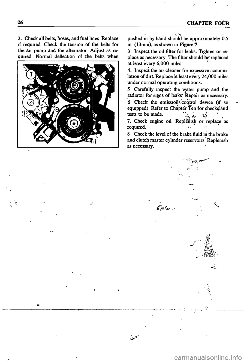
Normal
deflection
of
the
belts
when
pushed
m
by
hand
should
be
approXImately
0
5
m
13mm
as
shown
m
Figure
7
3
Inspect
the
011
filter
for
leaks
TIghten
or
re
place
as
necessary
The
filter
should
replaced
at
least
every
6
000
mIles
4
Inspect
the
lIlr
cleaner
for
excessIve
accumu
latIon
of
dIrt
Replace
at
least
every
24
000
miles
under
normal
operatmg
cornhtIons
5
Carefully
mspect
the
water
pump
and
the
radIator
for
SIgnS
of
leaks
Repair
as
necessl
i
y
6
Check
the
emissIoo
control
deVice
If
so
eqwpped
Refer
to
Chapter
Ten
for
checks
and
tests
to
be
made
c
1
7
Check
engine
oIl
Replems
9
or
replace
as
reqUIred
8
Check
the
level
of
the
brake
fluid
m
the
brake
and
clutcJ1
master
cylmder
reservOirs
ReplenISh
as
necessary
ii
t
d
fl
tlJ
l
Page 135 of 252
130
CHAPTER
ELEVEN
master
cylInder
operatlng
cylinder
and
with
drawal
lever
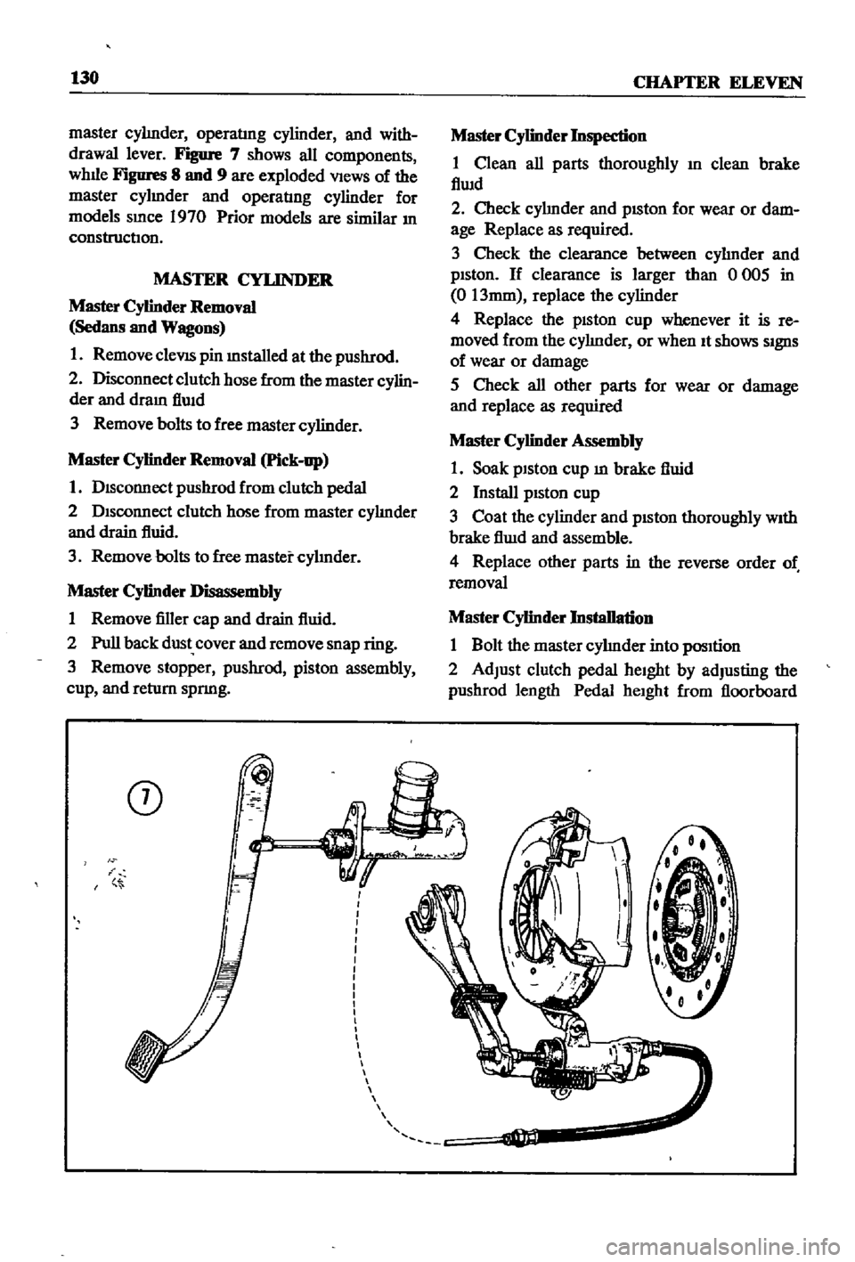
Figure
7
shows
all
components
whlle
Figures
8
and
9
are
exploded
VIews
of
the
master
cylmder
and
operatIng
cylinder
for
models
smce
1970
Prior
models
are
similar
In
construction
MASTER
CYLINDER
Master
Cylinder
Removal
Sedans
and
Wagons
1
Remove
cleVIS
pin
mstalled
at
the
pushrod
2
Disconnect
clutch
hose
from
the
master
cylin
der
and
dram
flwd
3
Remove
bolts
to
free
master
cylinder
Master
Cylinder
Removal
Pick
up
1
DIsconnect
pushrod
from
clutch
pedal
2
DIsconnect
clutch
hose
from
master
cylInder
and
drain
fluid
3
Remove
bolts
to
free
master
cylInder
Master
Cylinder
Disassembly
1
Remove
filler
cap
and
drain
fluid
2
Pull
back
dust
cover
and
remove
snap
ring
3
Remove
stopper
pushrod
piston
assembly
cup
and
return
spnng
CD
i
Master
Cylinder
Inspection
1
Clean
all
parts
thoroughly
In
clean
brake
flwd
2
Check
cylInder
and
pISton
for
wear
or
dam
age
Replace
as
required
3
Check
the
clearance
between
cylInder
and
pIston
If
clearance
is
larger
than
0
005
in
0
13mm
replace
the
cylinder
4
Replace
the
pISton
cup
whenever
it
is
re
moved
from
the
cylInder
or
when
It
shows
SIgnS
of
wear
or
damage
5
Check
all
other
parts
for
wear
or
damage
and
replace
as
required
Master
Cylinder
Assembly
1
Soak
piston
cup
m
brake
fluid
2
Install
pIston
cup
3
Coat
the
cylinder
and
pIston
thoroughly
WIth
brake
flwd
and
assemble
4
Replace
other
parts
in
the
reverse
order
of
removal
Master
Cylinder
Installation
1
Bolt
the
master
cylInder
into
pOSItion
2
Adjust
clutch
pedal
heIght
by
adjusting
the
pushrod
length
Pedal
heIght
from
floorboard
Page 138 of 252
CLUTCH
TRANSMISSION
AND
DRlVESIIAFI
133
C
8
Q@J
@
C
Operating
Cylinder
Reassembly
1
Soak
pISton
cup
m
brake
flUid
and
Install
It
In
the
same
pOSitIOn
as
before
removal
2
Apply
brake
flUid
to
the
cylInder
and
pIston
before
mstalImg
piston
3
Replace
all
parts
m
the
reverse
order
of
removal
Operating
Cylinder
Installation
1
RemstallatIon
IS
the
reverse
of
removal
2
Bleed
aIr
from
the
hydraulIc
system
3
Adjust
the
pushrod
so
that
withdrawal
lever
end
play
IS
0
0787
to
0
1181
In
2
0
to
3
Omm
Procedures
for
the
adjustment
are
given
below
WITHDRAWAL
LEVER
AD
JUSTMENT
Correct
adjustment
of
the
clutch
withdrawal
lever
IS
essentIal
InsufficIent
free
travel
between
the
release
bearmg
and
dIaphragm
fingers
can
cause
the
clutch
to
slIp
ExceSSIve
free
travel
can
prevent
full
dISengagement
of
the
clutch
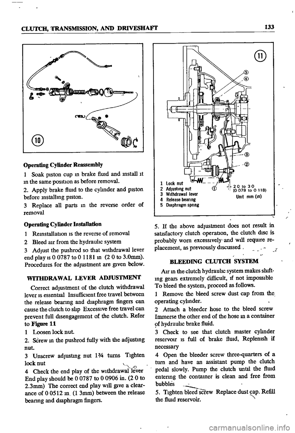
Refer
to
Figure
11
1
Loosen
lock
nut
2
SCrew
In
the
pushrod
fully
with
the
adjustmg
nut
3
Unscrew
adJustmg
nut
1
turns
TIghten
lock
nut
J
4
Check
the
end
play
of
the
wIthdrawal
lever
End
play
should
be
0
0787
to
0
0906
in
2
0
to
2
3mm
The
correct
end
play
will
give
a
clear
ance
of
0
0512
m
1
3mm
between
the
release
bearmg
and
diaphragm
fingers
@
1
Lock
nut
2
AdJustmg
nut
3
Wrthdrawal
ever
4
Release
beer
ng
5
Diaphragm
spnng
20
to
30
0
079
to
0
11
B
Unit
mm
m
5
If
the
above
adjustment
does
not
result
in
satIsfactory
clutch
operatIon
the
clutch
dISC
is
probably
worn
excessIvely
and
will
reqUire
re
placement
as
preVIously
dIScussed
BLEEDING
CLUTCH
SYSTEM
AIr
In
the
clutch
hydraulIc
system
makes
shIft
Ing
gears
extremely
difficult
1f
not
impOSSIble
To
bleed
the
system
proceed
as
follows
1
Remove
the
bleed
screw
dust
cap
from
the
operating
cylInder
2
Attach
a
bleeder
hose
to
the
bleed
screw
Immerse
the
other
end
of
the
hose
m
a
container
f
hydraulIc
brake
fluid
3
Check
to
see
that
clutch
master
cylInder
reservoir
IS
full
of
brake
flUid
ReplenISh
if
necessary
4
Open
the
bleeder
screw
three
quarters
of
a
tlIrn
and
have
an
assistant
pump
the
clutch
pedal
slowly
Pump
the
clutch
until
the
flUid
entenng
the
contatner
is
clean
and
free
from
bubbles
5
TIghten
bleed
screw
Replace
dust
cap
Refill
the
flUid
reservoir
Page 152 of 252
CLUTCH
TRANSMISSION
AND
DRIVESHAFI
147
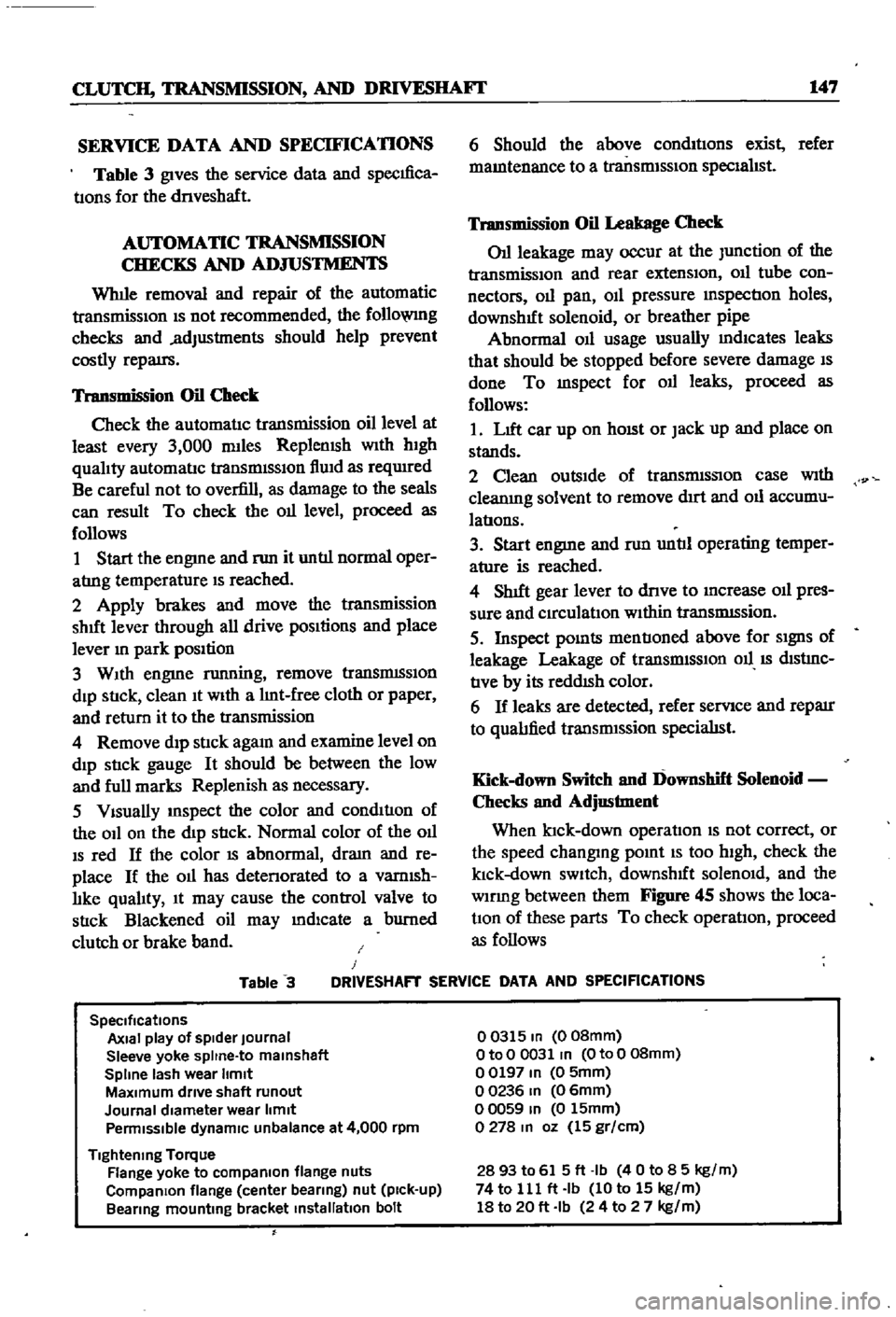
SERVICE
DATA
AND
SPECIFICATIONS
Table
3
gives
the
service
data
and
specIfica
tIons
for
the
dnveshaft
AUTOMATIC
TRANSMISSION
CHECKS
AND
ADJUSTMENTS
Whlle
removal
and
repair
of
the
automatic
transmisSIOn
IS
not
recommended
the
follo
VlIlg
checks
and
adjustments
should
help
prevent
costly
repatrs
Transmission
Oil
Check
Check
the
automatIc
transmission
oil
level
at
least
every
3
000
mlles
Replemsh
With
hIgh
qualIty
automatIc
transmISSIon
flUId
as
reqUIred
Be
careful
not
to
overfill
as
damage
to
the
seals
can
result
To
check
the
011
level
proceed
as
follows
1
Start
the
engme
and
nm
it
untIl
normal
oper
atrng
temperature
IS
reached
2
Apply
brakes
and
move
the
transmission
shut
lever
through
all
drive
pOSItions
and
place
lever
In
park
position
3
WIth
engme
running
remove
tranSmISSIon
dIp
StIck
clean
It
WIth
a
lInt
free
cloth
or
paper
and
return
it
to
the
transmission
4
Remove
dIp
stIck
agam
and
examine
level
on
dIp
stIck
gauge
It
should
be
between
the
low
and
full
marks
Replenish
as
necessary
5
VIsually
InSpect
the
color
and
condItIon
of
the
OIl
on
the
dIp
stIck
Normal
color
of
the
OIl
IS
red
If
the
color
IS
abnormal
dram
and
re
place
If
the
011
has
detenorated
to
a
vamlsh
lIke
qualIty
It
may
cause
the
control
valve
to
stIck
Blackened
oil
may
mdlcate
a
burned
clutch
or
brake
band
6
Should
the
above
condItIons
exist
refer
mamtenance
to
a
transmISSIon
specIalIst
Transmission
Oil
Leakage
Check
011
leakage
may
occur
at
the
Junction
of
the
transmissIon
and
rear
extensIon
011
tube
con
nectors
011
pan
OIl
pressure
mspectIon
holes
downshIft
solenoid
or
breather
pipe
Abnormal
OIl
usage
usually
mdlcates
leaks
that
should
be
stopped
before
severe
damage
IS
done
To
mspect
for
011
leaks
proceed
as
follows
1
LIft
car
up
on
hOISt
or
Jack
up
and
place
on
stands
2
Clean
outsIde
of
transmISSIon
case
With
cleanIng
solvent
to
remove
dIrt
and
011
accumu
latIons
3
Start
engme
and
nm
untIl
operating
temper
ature
is
reached
4
ShIft
gear
lever
to
dnve
to
Increase
011
pres
sure
and
CIrculatIon
WIthin
tranSmISsion
5
Inspect
pOInts
mentIoned
above
for
SIgnS
of
leakage
Leakage
of
transrmSSIOn
011
IS
dIStrnC
tIve
by
its
reddISh
color
6
If
leaks
are
detected
refer
servIce
and
reparr
to
qualIfied
transrmssion
specialISt
Kick
down
Switch
and
Downshift
Solenoid
Checks
and
Adjustment
When
ktck
down
operatIon
IS
not
correct
or
the
speed
changmg
pomt
IS
too
high
check
the
klck
down
SWItch
downshIft
solenOId
and
the
wlDng
between
them
Figure
45
shows
the
loca
tIOn
of
these
parts
To
check
operatIon
proceed
as
follows
Table
3
J
DRIVESHAFT
SERVICE
DATA
AND
SPECIFICATIONS
SpeCifications
Axial
play
of
spider
Journal
Sleeve
yoke
spltne
to
malnshaft
Spline
lash
wear
Itmlt
MaXimum
drive
shaft
runout
Journal
diameter
wear
limit
Penmlsslble
dynamiC
unbalance
at
4
000
rpm
Tightening
Torque
Flange
yoke
to
compaRlon
flange
nuts
CompaRlon
flange
center
bearing
nut
pick
up
Bearing
mounting
bracket
installation
bolt
00315
In
008mm
OtoO
0031
In
OtoO
08mm
00197
In
0
5mm
00236
In
06mm
00059
In
0
15mm
0278
In
oz
15
gr
cm
2893
to
615ft
Ib
40
to
8
5
kg
m
74
to
111
ft
Ib
10
to
15
kg
m
18
to
20
ft
Ib
24
to
2
7
kg
m
Page 193 of 252
J
188
CHAPTER
FOURTEEN
Brake
Pedal
Installation
1
Apply
pedal
grease
to
the
pedal
shaft
sleeves
and
push
rod
cleVIS
pm
2
Installation
is
the
reverse
of
removal
3
Torque
the
fulcrum
pm
to
25
3
to
28
9
ft
lb
3
5
to
4
0
kg
m
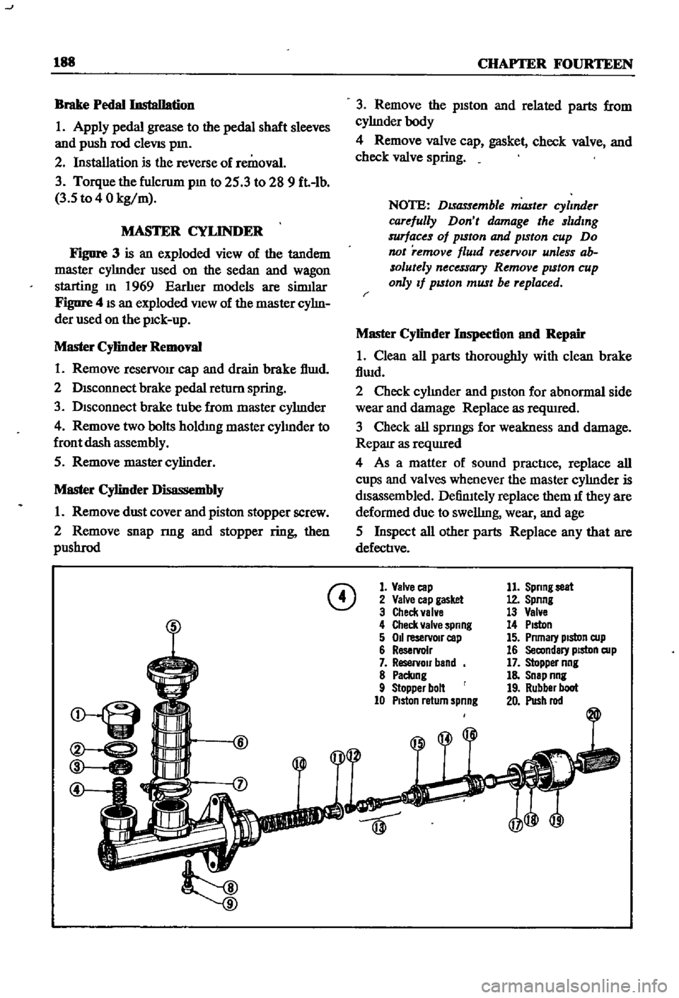
MASTER
CYLINDER
FIgure
3
is
an
exploded
view
of
the
tandem
master
cyhnder
used
on
the
sedan
and
wagon
starting
m
1969
Earher
models
are
sinnlar
Figure
4
IS
an
exploded
View
of
the
master
cyhn
der
used
on
the
pIck
up
Master
Cylinder
Removal
1
Remove
reservOIr
cap
and
drain
brake
f1wd
2
DISconnect
brake
pedal
return
spring
3
Disconnect
brake
tube
from
master
cyhnder
4
Remove
two
bolts
holdmg
master
cyhnder
to
front
dash
assembly
5
Remove
master
cylinder
Master
Cylinder
Disassembly
1
Remove
dust
cover
and
piston
stopper
screw
2
Remove
snap
nng
and
stopper
ring
then
pllShrod
3
Remove
the
piston
and
related
parts
from
cyhnderbody
4
Remove
valve
cap
gasket
check
valve
and
check
valve
spring
NOTE
DISassemble
master
cylmder
carefully
Don
t
damage
the
slldmg
surfaces
of
pISton
and
pISton
cup
Do
not
remove
flUId
reservOlT
unless
ab
solutely
necessary
Remove
pISton
cup
only
If
pISton
must
be
replaced
r
Master
Cylinder
Inspection
nnd
Repair
1
Clean
all
parts
thoroughly
with
clean
brake
fiwd
2
Check
cyhnder
and
piston
for
abnormal
side
wear
and
damage
Replace
as
reqUIred
3
Check
all
spnngs
for
weakness
and
damage
Reparr
as
reqUIred
4
As
a
matter
of
sound
practIce
replace
all
cups
and
valves
whenever
the
master
cyhnder
is
dISassembled
DefinItely
replace
them
1f
they
are
deformed
due
to
swellmg
wear
and
age
5
Inspect
all
other
parts
Replace
any
that
are
defective
CD
1
Valve
cap
2
Valve
cap
gasket
3
Check
valve
4
Check
valve
spnng
5
011
reservoIr
cap
6
Reservoir
7
ReservOir
band
8
Paclang
9
Stopper
bolt
10
PIston
return
spnng
11
Sprmg
seat
12
Spnng
13
Valve
14
PIston
15
Pnmary
pIston
cup
16
Secondary
piston
cup
17
Stopper
nng
18
Snap
nng
19
Rubber
boot
20
Push
rod
Page 195 of 252
190
CHAPTER
FOURTEEN
Master
Cylinder
Assembly
and
Installation
I
Assemble
the
master
cyhnder
m
the
reverse
order
of
dIsassembly
2
Pnor
to
assembly
soak
piston
cap
m
brake
flwd
Install
piston
so
that
It
seats
firmly
on
the
piston
cup
3
Coat
the
cyhnder
bore
and
pISton
assemblies
With
clean
brake
flwd
before
assembly
4
When
assembly
IS
complete
mount
master
cylmder
on
dash
wall
and
hook
connecting
rod
to
brake
pedal
Replace
return
sprmg
Fill
the
reservOir
With
clean
brake
flUid
5
If
aIr
has
seeped
mto
the
brake
Imes
bleed
the
brakes
as
descnbed
later
m
thIS
chapter
FRONT
DISC
BRAKES
SEDAN
AND
WAGON
Brake
Pad
Replacement
Pad
wear
should
be
checked
every
4
000
nuIes
Clearance
between
the
pad
and
the
rotor
IS
adjusted
automatIcally
and
therefore
IS
not
a
wear
mdlcator
Pad
thiCknesS
IS
checked
by
re
movmg
the
antI
rattle
clJp
When
the
pad
hning
becomes
worn
to
0
04
Imm
replace
all
pads
on
the
front
wheels
I
Remove
the
hub
cap
loosen
the
hub
nuts
jack
up
the
vehicle
support
with
stands
and
remove
the
front
wheels
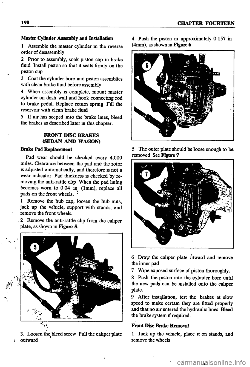
2
Remove
the
antI
rattle
clJp
from
the
caliper
plate
as
shown
m
Figure
S
jty
3
Loosen
the
bleed
screw
Pull
the
calJper
plate
outward
4
Push
the
pISton
m
approximately
0
157
in
4mm
as
shown
m
Figure
6
5
The
outer
plate
should
be
loose
enough
to
be
removed
See
Figure
7
6
Dra
y
the
calJper
plate
rlfward
and
remove
the
inner
pad
7
Wipe
exposed
surface
of
piston
thoroughly
8
Push
the
piston
mto
the
cyhnder
bore
untJI
the
new
pads
can
be
mstalled
onto
the
calJper
plate
9
After
instl
llatIon
test
the
brakes
at
slow
speed
to
make
certam
they
are
fitted
properly
and
that
no
au
entered
the
hydraul1c
hnes
Bleed
the
brake
system
If
required
Front
Disc
Brake
Removal
I
Jack
up
the
vehicle
place
It
on
stands
and
remove
the
wheels
P
Page 198 of 252
BRAKES
193
Front
Disc
Brake
Piston
Seal
Replacement
If
oil
leakage
is
detected
around
the
piston
seal
It
should
be
replaced
as
follows
I
Rinse
the
cyhnder
bore
With
brake
flwd
In
sert
new
seal
into
the
groove
taking
care
not
to
damage
It
Attach
the
wiper
seal
Lubricate
cylinder
bore
lightly
With
brake
fluid
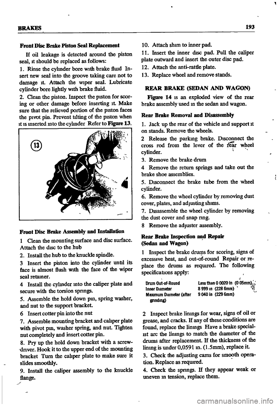
2
Clean
the
piston
Inspect
the
pISton
for
scor
ing
or
other
damage
before
inserting
It
Make
sure
that
the
relieved
portion
of
the
pISton
faces
the
pivot
pin
Prevent
tilting
of
the
piston
when
It
IS
mserted
mto
the
cyhnder
Refer
to
Figure
13
@
4
Front
Disc
Brake
Assembly
and
Installation
I
Clean
the
mounting
surface
and
disc
surface
Attach
the
disc
to
the
hub
2
Install
the
hub
to
the
knuckle
spindle
3
Insert
the
piston
into
the
cylinder
untIl
its
face
is
almost
flush
With
the
face
of
the
wiper
seal
retamer
4
Install
the
cyhnder
mto
the
caliper
plate
and
secure
with
the
torsion
spnngs
5
Assemble
the
hold
down
pm
spring
washer
and
nut
to
the
support
bracket
6
Insert
cotter
pin
into
the
nut
7
Assemble
mounting
bracket
and
calJper
plate
with
pivot
pm
washer
spring
and
nut
Tighten
nut
completely
and
insert
cotter
pin
8
Pry
up
the
hold
down
bracket
with
a
screw
dnver
Hook
it
to
the
upper
end
of
the
mounting
bracket
Turn
the
cal1per
plate
to
make
sure
it
slides
smoothly
9
Install
the
caliper
assembly
to
the
knuckle
flange
10
Attach
shun
to
inner
pad
I
I
Insert
the
inner
dIsc
pad
Pull
the
caliper
plate
outward
and
insert
the
outer
disc
pad
12
Attach
the
anti
rattle
plate
13
Replace
wheel
and
remove
stands
REAR
BRAKE
SEDAN
AND
WAGON
Figure
14
IS
an
exploded
view
of
the
rear
brake
assembly
used
m
the
sedan
and
wagon
Rear
Brake
Removal
and
Disassembly
1
Jack
up
the
rear
of
the
vehicle
and
support
It
on
stands
Remove
the
wheels
2
Release
the
parkIng
brake
DISConnect
the
cross
rod
from
the
lever
of
the
ie
wheel
cylinder
3
Remove
the
brake
drum
4
Remove
the
return
springs
and
take
out
the
brake
shoe
assemblies
5
Disconnect
the
brake
tube
from
the
wheel
cylinder
6
Remove
the
wheel
cylinder
by
removing
dust
cover
plates
and
adJusting
shIms
7
DISassemble
the
wheel
cylinder
by
removing
the
dust
cover
and
snap
nng
8
Remove
the
adJuster
assembly
Rear
Brake
Inspection
d
Repair
Sedan
and
Wagon
I
Inspect
the
brake
druf
1s
for
scoring
signs
of
excessive
heat
and
out
of
round
Repair
or
re
place
the
drums
as
reqUIred
The
following
specificatIons
apply
Drum
Out
of
Round
Inner
Olameter
MaXImum
Diameter
after
IlI1ndmg
Less
than
0
0020
In
0
05mm
8
999
m
228
6mm
1
9040
In
229
6mm
2
Inspect
brake
limngs
for
wear
signs
of
oil
or
grease
and
cracks
If
any
of
these
conditions
are
found
replace
the
linmgs
Have
a
brake
special
ISt
arc
the
limngs
to
match
the
diameter
of
the
drums
after
replacement
If
the
thickness
of
the
limng
is
under
0
0591
m
1
5mm
replace
it
3
Check
the
adjusting
cams
for
smooth
opera
tion
Replace
as
reqUIred
4
Check
the
spnngs
If
they
appear
weak
or
uneven
m
tension
replace
them