Page 199 of 252

v
194
CHAPTER
FOURTEEN
3
Right
hand
rear
brake
disc
4
Left
hand
rear
brake
disc
5
Fore
rear
brake
shoe
6
Aft
rear
brake
shoe
7
Brake
IImng
8
Rear
brake
adjuster
9
Adjuster
wedge
11
Lock
washer
12
Hex
nut
13
Wheel
cylinder
assembly
14
Piston
cup
15
Piston
16
Dust
cover
6
@
5
Check
the
wheel
cylinder
for
wear
rust
and
damage
If
defectIve
replace
6
Check
die
clearance
between
th
cyhnder
and
the
piston
If
the
clearance
18
greater
than
Q
0059
m
0
15mm
replace
the
cylinder
The
cyluiders
can
be
honed
With
a
wheel
cyhnder
hone
If
the
maXImum
dimensIOn
has
not
been
reached
7
Replace
the
piston
cups
whenever
the
cyhn
derds
disassembled
even
though
the
cups
appear
to
be
m
good
condition
Rear
Brake
Assembly
1
Assembly
IS
the
reverse
of
disassembly
2
Be
careful
not
to
get
dirt
or
brake
fluid
on
the
brake
hnnlgs
3
AdJust
shoe
clearance
then
bleed
the
hy
draulIc
system
17
Dust
cover
ring
18
21
Lock
plates
22
Dust
cover
23
Lever
assembly
24
Bleeder
screw
25
Bleeder
cap
26
Return
spring
27
Return
spring
adjuster
slide
29
Anti
rattle
spring
30
Anti
rattle
pin
31
Anti
rattle
spring
set
32
Anti
rattle
retainer
spring
23
22
24
e
17
a
25
FRONT
BRAKE
pICK
UP
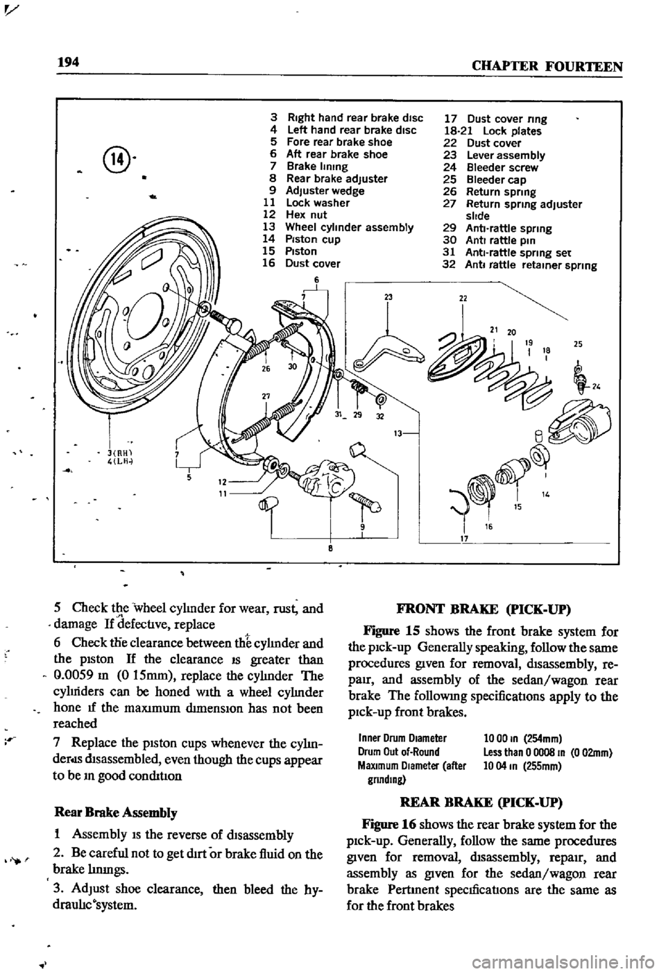
Figure
15
shows
the
front
brake
system
for
the
pick
up
Generally
speaking
follow
the
same
procedures
given
for
removal
disassembly
re
pair
and
assembly
of
the
sedan
wagon
rear
brake
The
followmg
specifications
apply
to
the
pick
up
front
brakes
Inner
Drum
Diameter
Drum
Out
of
Round
MaXimum
DIameter
after
gnndlng
10
00
In
254mm
Less
than
0
0008
In
0
02mm
10
04
In
255mm
REAR
BRAKE
pICK
UP
Figure
16
shows
the
rear
brake
system
for
the
pick
up
Generally
follow
the
same
procedures
given
for
removal
disassembly
repaIr
and
assembly
as
given
for
the
sedan
wagon
rear
brake
Pertment
specificatIons
are
the
same
as
for
the
front
brakes
Page 201 of 252

196
CHAPTER
FOURTEEN
WHEEL
CYLINDERS
pICK
UP
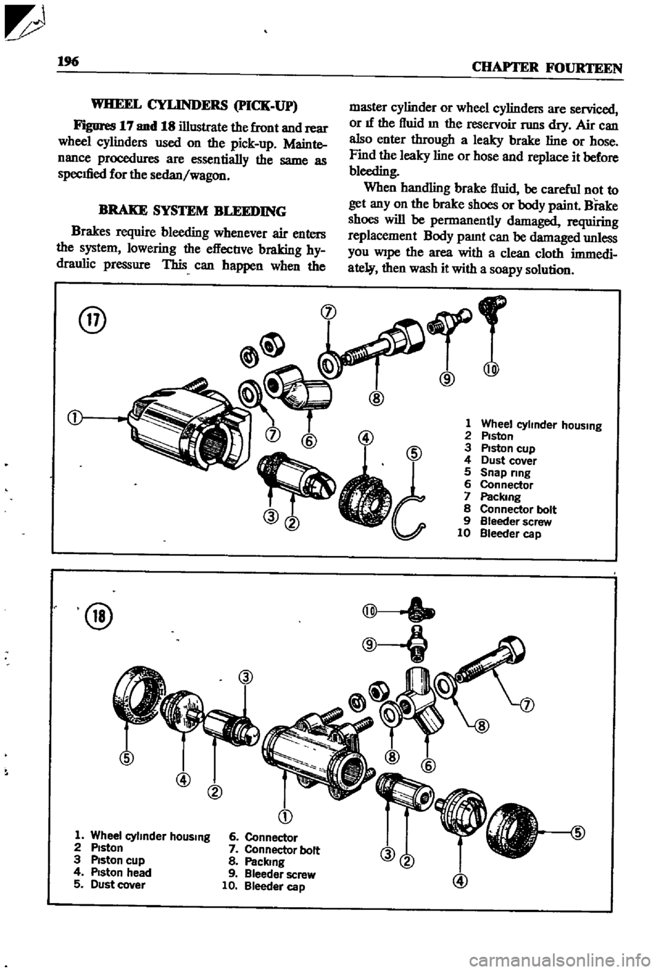
Figures
17
and
18
illustrate
the
front
and
rear
wheel
cylinders
used
on
the
pick
up
Mainte
nance
procedures
are
essentially
the
same
as
specIfied
for
the
sedan
wagon
BRAKE
SYSTEM
BLEEDING
Brakes
require
bleeding
whenever
air
enters
the
system
lowering
the
effectIve
braking
hy
draulic
pressure
This
can
happen
when
the
@
@
@
@
D
1
Wheel
cylmder
hOUSing
2
Piston
3
Piston
cup
4
Piston
head
5
Dust
cover
6
Connector
7
Connector
bolt
8
Paclang
9
Bleeder
screw
10
Bleeder
cap
master
cylinder
or
wheel
cylinders
are
serviced
or
If
the
fluid
m
the
reservoir
TWlS
dry
Air
can
also
enter
through
a
leaky
brake
line
or
hose
Find
the
leaky
line
or
hose
and
replace
it
before
bleeding
When
handling
brake
fluid
be
careful
not
to
get
any
on
the
brake
shoes
or
body
paint
Brake
shoes
will
be
permanently
damaged
requiring
replacement
Body
pamt
can
be
damaged
unless
you
Wipe
the
area
with
a
clean
cloth
immedi
ate
then
wash
it
with
a
soapy
solution
r
@
@
1
Wheel
cyhnder
hOUSing
2
Piston
3
Piston
cup
4
Dust
cover
5
Snap
ring
6
Connector
7
Packmg
8
Connector
bolt
9
Bleeder
screw
10
Bleeder
cap
@
Page 202 of 252

BRAKES
IV
197
I
Ensure
that
the
brake
flUid
reservOir
at
the
master
cylmder
IS
full
and
that
the
vent
m
the
cap
is
open
2
Connect
a
plastIc
or
rubber
tube
to
the
bleeder
valve
on
the
nght
rear
wheel
Suspend
the
other
end
of
the
tube
m
a
Jar
or
bottle
filled
With
a
few
Inches
of
clean
brake
flwd
During
the
remaInIng
steps
keep
thiS
end
submerged
at
all
times
and
never
let
the
level
in
the
brake
flUid
reservoir
drop
below
full
3
Open
the
bleeder
valve
on
the
nght
rear
wheel
about
one
turn
Have
an
asSistant
depress
the
brake
pedal
slowly
As
soon
as
the
pedal
is
all
the
way
down
close
the
bleeder
valve
and
let
the
pedal
up
Repeat
thiS
step
as
many
tImes
as
necessary
until
pure
flUid
WithOUt
au
bubbles
comes
from
the
tube
4
Bleed
the
remammg
wheels
m
the
followmg
order
left
rear
nght
front
and
left
front
Keep
checkmg
the
brake
flUid
reservoir
to
make
cer
tam
It
doesn
t
TWl
out
of
flUId
5
When
all
wheels
are
bled
fill
the
reservOIr
to
the
full
level
Never
reuse
the
brake
flwd
bled
from
the
system
or
any
that
has
been
lymg
around
Start
With
a
fresh
contaIner
HANDBRAKE
Figures
19
next
page
and
20
page
199
are
exploded
views
of
the
handbrake
system
used
on
the
sedan
and
statIon
wagon
respectively
F1gDre
21
page
200
shows
the
pick
up
handbrake
system
Front
Cable
Removal
Sedan
and
Wagon
I
Release
handbrake
completely
Disconnect
the
front
cable
by
removmg
the
cleVIS
pm
that
connects
to
the
handbrake
control
stem
2
Screw
out
the
adJusting
nut
from
the
rear
end
of
the
front
cable
Disconnect
the
cable
from
the
center
lever
4
Remove
the
hand
brake
cable
clamp
from
under
the
verucle
Pull
out
the
lock
plate
fixmg
the
front
cable
to
the
front
cable
retamer
Ex
tract
the
front
cable
5
Unfasten
the
front
cable
outer
casing
from
the
bracket
Remove
the
cable
Front
Cable
Removal
Pick
up
I
Loosen
handbrake
2
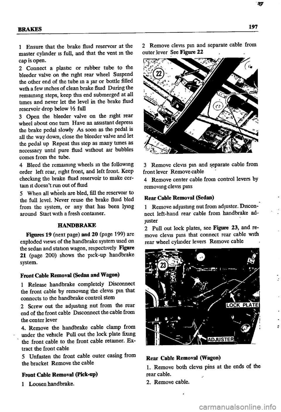
Remove
cleVIS
pm
and
separate
cable
from
outer
lever
See
Figure
22
p
3
Remove
cleVIS
pm
and
eparate
cable
from
front
lever
Removecable
4
Remove
center
cable
from
control
levers
by
removmg
cleViS
pms
Rear
Cable
Removal
Sedan
I
Remove
adJusting
nut
from
adJuster
DIScon
nect
left
hand
rear
cable
from
handbrake
ad
Juster
2
Pull
out
lock
plates
see
Figure
23
and
re
move
cleVIS
pms
that
connect
rear
cable
With
rear
wheel
cylJnder
levers
Remove
cable
Rear
Cable
Removal
Wagon
1
Remove
both
cleVIS
pins
at
the
ends
of
the
rear
cable
2
Remove
cable