1968 DATSUN 510 radiator cap
[x] Cancel search: radiator capPage 12 of 252

PERIODIC
MAINTENANCE
7
Table
1
ENGINE
LUBRICATION
AND
MAINTENANCE
FREQUENCY
EVERY
E
E
E
E
E
E
E
Eo
00
00
00
00
00
00
00
gq
00
00
00
NO
t
r61li
0
CD
Check
engine
011
level
top
up
If
required
X
Change
engine
011
X
Lubricate
carburetor
hnkage
X
Lubricate
distributor
rotor
shaft
and
ann
shaft
X
Apply
grease
to
distributor
cam
heel
X
Check
radiator
coolant
level
X
Change
radIator
coolant
X
Change
radiator
coolant
additive
X
Check
battery
electrolyte
level
X
Check
specific
gravity
of
battery
X
Check
engine
starting
exhaust
color
X
Tighten
cyhnder
head
manifolds
and
pipe
flanges
X
Adjust
valve
clearance
X
Check
Ignition
timing
X
Tighten
carburetor
fittings
X
Check
fan
belt
tension
X
Check
for
011
pan
leakage
X
Tighten
engine
mounts
X
Check
fuel
strainer
X
Replace
fuel
strainer
X
Check
for
fuel
leaks
X
Replace
011
filter
X
Check
spark
plugs
X
Replace
spark
plugs
X
Check
dlstnbutor
cap
rotor
and
POints
X
Adjust
engine
Idle
speed
X
Check
air
cleaner
fittings
X
Clean
011
filler
cap
X
Clean
battery
cables
and
terminals
X
Check
alternator
and
voltage
regulator
function
X
Check
starter
motor
function
X
Replace
aIr
cleaner
element
X
Check
fuel
pump
function
X
Check
cyhnder
compressIon
X
Clean
carburetor
Jets
and
float
chamber
X
Check
dlstnbutor
condenser
X
Check
crankcase
ventilation
control
valve
X
Page 64 of 252

ENGINE
59
2
Coat
the
pan
gasket
on
both
sides
With
gasket
compound
and
attach
the
oil
pan
to
the
cyhnder
block
Torque
as
specIfied
Manifold
and
Carburetor
Installation
1
Install
the
mtake
and
exhaust
manIfolds
WIth
associated
gasket
to
the
cylmder
head
2
Mount
the
carburetor
and
gasket
to
the
mtake
manIfold
2
Adjust
all
mtake
and
exhaust
valves
to
the
specIfied
clearance
for
a
cold
engme
Clutch
Assembly
Installation
CAUTION
Take
extreme
care
not
to
get
grease
or
011
on
the
clutch
or
flywheel
frlc
hon
contact
surfaces
1
Place
the
clutch
disc
assembly
on
the
flywheel
With
the
longer
chamfered
splmed
end
of
the
dISC
toward
the
transmISSion
2
Visually
align
or
use
a
dummy
splmed
dnve
shaft
to
ahgn
the
diSC
assembly
With
the
flywheel
pilot
beanng
3
Install
and
tighten
the
SIX
bolts
holdmg
the
clutch
cover
assembly
to
the
flywheel
Tighten
the
bolts
a
turn
each
tune
by
diagonal
pattern
until
they
are
tight
Tlghtenmg
torque
should
be
174
to
188ft
lbs
24
to
2
6
kg
m
NOTE
There
are
two
dowels
on
the
flywheel
to
locate
the
clutch
cover
4
Remove
dummy
shaft
If
used
after
the
above
bolts
are
fully
tightened
5
Refit
the
release
bearing
and
translI11Ssion
case
Miscellaneous
Installation
1
Connect
the
fuel
hose
on
the
front
part
of
the
engme
to
the
fuel
pump
and
to
the
carburetor
2
Gap
the
spark
plugs
and
mstall
them
usmg
new
gaskets
3
Coat
the
rocker
arm
cover
gasket
With
sealer
and
position
It
on
the
cylmder
head
4
Install
the
rocker
arm
cover
and
tighten
the
two
thumb
screws
that
hold
it
m
place
5
Install
distrIbutor
makmg
certam
that
the
notch
on
the
distributor
shaft
assembly
mates
With
the
drive
spmdle
Ahgn
the
location
marks
made
dunng
disassembly
so
that
the
distrIbutor
is
positioned
as
before
6
Install
and
tighten
the
bolts
which
hold
the
dIStributor
to
the
front
cover
7
Install
pomts
condenser
and
rotor
8
Replace
distrIbutor
cap
and
attach
spark
plug
Wires
m
the
correct
sequence
Make
certain
that
all
wires
are
firmly
seated
m
the
distrIbutor
cap
and
attached
securely
to
the
spark
plugs
9
HOISt
the
engme
assembly
from
the
work
stand
10
Install
the
alternator
bracket
alternator
and
engme
mounts
to
the
block
11
Install
the
IgnItIon
coil
oil
filter
oil
pressure
SWitch
dipstick
and
water
drain
plug
12
Connect
the
vacuum
Ime
between
the
dis
trIbutor
and
carburetor
13
Connect
the
transIDlSSlOn
to
the
engine
prior
to
mstallatIon
m
the
vehicle
Engine
Installation
Installation
is
the
reverse
of
the
procedures
followed
m
removal
Be
certaIn
thatlall
battery
connections
are
made
that
water
hoses
are
se
cured
wmng
IS
connected
properly
and
that
all
required
bolts
and
mounts
are
mstalled
and
tightened
Replace
the
radiator
fan
belts
and
radiator
shroud
Fill
the
engme
With
the
proper
grade
of
oil
and
the
radiator
With
recommended
coolant
Install
the
hood
to
the
hInges
according
to
the
marks
made
dUrIng
removal
SERVICE
DATA
AND
SPECIFICATIONS
Table
1
covers
servIce
data
and
engme
Speci
fications
Page 95 of 252

90
CHAPTER
EIGHT
degrees
C
The
maXImum
WIdth
of
the
thermo
stat
openIng
should
be
0315
In
8mm
3
If
the
thermostat
IS
defectIve
or
If
you
have
an
doubts
about
It
mstall
a
new
one
4
When
Installmg
the
thermostat
m
the
hous
Ing
be
certaIn
to
place
the
spnng
end
down
Coat
both
SIdes
of
the
gasket
WIth
sealer
to
pre
vent
leaks
and
tIghten
the
mountlng
nuts
securely
RADIATOR
The
radIator
IS
of
conventional
desIgn
A
draIn
cock
IS
proVIded
at
the
bottom
back
to
perrmt
drainIng
The
system
IS
pressurized
and
the
rehef
valve
incorporated
In
the
filler
cap
mamtains
the
pressure
at
approximately
12
8
Ib
in
0
9
kg
cm
Coolant
capacity
is
1
691
gallons
6
4
lIters
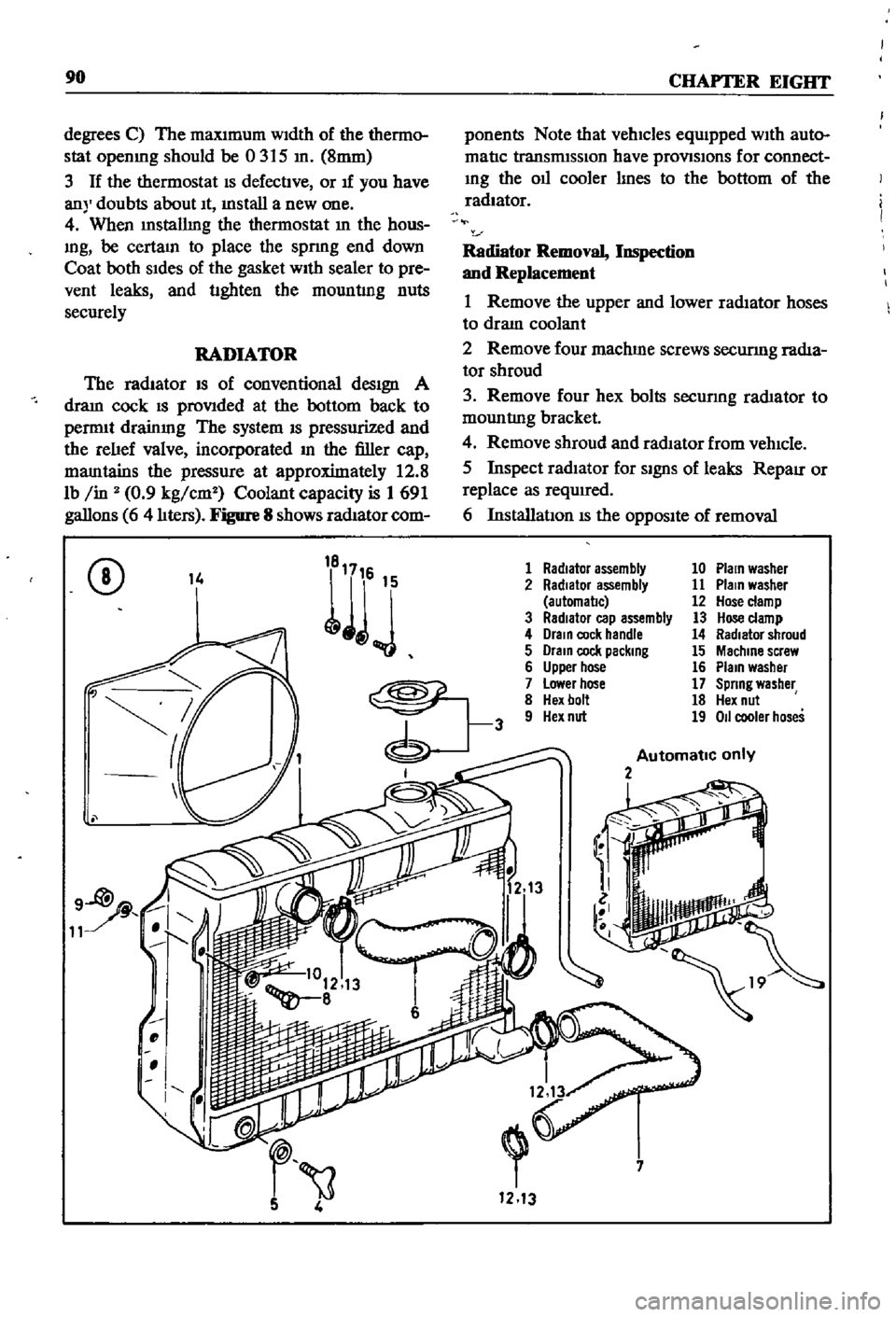
Figure
8
shows
radIator
com
ponents
Note
that
vehicles
equIpped
WIth
auto
matIc
transmISSIon
have
provlSlons
for
connect
Ing
the
011
cooler
lInes
to
the
bottom
of
the
radiator
Radiator
Removal
Inspection
and
Replacement
1
Remove
the
upper
and
lower
radIator
hoses
to
draIn
coolant
2
Remove
four
machme
screws
securmg
radIa
tor
shroud
3
Remove
four
hex
bolts
secunng
rad1ator
to
mountlng
bracket
4
Remove
shroud
and
radIator
from
vehIcle
5
Inspect
radIator
for
SignS
of
leaks
RepaIr
or
replace
as
required
6
InstallatIon
IS
the
OppOSIte
of
removal
CD
14
1
Radiator
assembly
10
Plain
washer
2
Radiator
assembly
11
Plain
washer
automal1c
12
Hose
clamp
3
RadIator
cap
assembly
13
Hose
clamp
4
Drain
cock
handle
14
Radiator
shroud
5
Drain
cock
packing
15
Machine
screw
6
Upper
hose
16
Plain
washer
7
Lower
hose
17
Spring
washer
8
Hex
bolt
18
Hex
nut
9
Hex
nut
19
011
cooler
hoses
Automatic
only
2
i
7
1213
Page 231 of 252

1
Radiator
grille
5
Screw
6
Washer
7
Washer
8
9
Head
lamp
finIsher
10
Screw
11
Nut
12
Hood
top
moulding
14
Screw
15
Washer
16
Moulding
19
Moulding
21
Front
apron
23
Front
bumper
24
Hex
bolt
with
washer
25
Washer
26
27
Bumper
stay
28
Bolt
29
Nut
30
Washer
31
Washer
32
Plug
34
35
Overrlder
36
Rubber
37
Washer
38
Lock
washer
39
Nut
40
41
Front
Fender
43
Hood
assembly
44
45
Hood
hinge
46
Bolt
47
Washer
48
49
Cowl
panel
50
Cowl
grille
51
Cowl
grille
cap
52
Sealing
rubber
52
1
14
V
27
r
l
DETAIL
A
23
8
41
t
l