1968 DATSUN 510 fuse
[x] Cancel search: fusePage 5 of 252
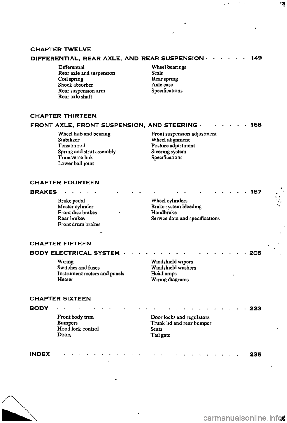
CHAPTER
TWELVE
DIFFERENTIAL
REAR
AXLE
AND
REAR
SUSPENSION
149
DIfferentIal
Rear
axle
and
suspension
Codspnng
Shock
absorber
Rear
suspensIOn
arm
Rear
axle
shaft
Wheel
beanngs
Seals
Rear
spnng
Axle
case
SpecificatIons
CHAPTER
THIRTEEN
FRONT
AXLE
FRONT
SUSPENSION
AND
STEERING
168
Wheel
hub
and
bearmg
StabilIzer
TenSion
rod
Spnng
and
strut
assembly
Transverse
lInk
Lower
ball
Jomt
Front
suspension
adjustment
Wheel
alignment
Posture
adJustment
Steenng
system
SpeCificatIons
CHAPTER
FOURTEEN
BRAKES
187
Brake
pedal
Master
cylInder
Front
diSC
brakes
Rear
brakes
Front
drum
brakes
Wheel
cylInders
Brake
system
bleedIng
Handbrake
Service
data
and
speCificatIons
CHAPTER
FIFTEEN
BODY
ELECTRICAL
SYSTEM
Wmng
SWitches
and
fuses
Instrument
meters
and
panels
Heater
205
Wmdshleld
wipers
Wmdslueld
washers
Headlamps
WIrIng
diagrams
CHAPTER
SIXTEEN
BODY
223
Front
body
trIm
Bumpers
Hood
lock
control
Doors
Door
locks
and
regulators
Trunk
lId
and
rear
bumper
Seats
Tad
gate
INDEX
235
I
Page 14 of 252
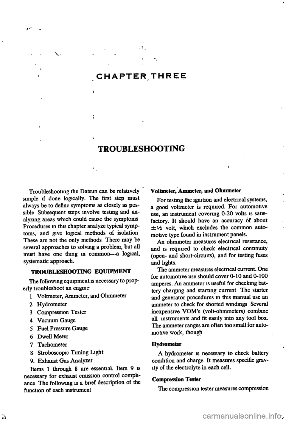
CHAPTER
THREE
TROUBLESHOOTING
TroubleshootIng
the
Datsun
can
be
relatlvely
simple
1f
done
lOgically
The
first
step
must
always
be
to
define
symptoms
as
closely
as
pos
Sible
Subsequent
steps
mvolve
testIng
and
an
alyzmg
areas
which
could
cause
the
symptoms
Procedures
m
thiS
chapter
analyze
typical
symp
toms
and
give
lOgical
methods
of
isolation
These
are
not
the
only
methods
There
may
be
several
approaches
to
solvmg
a
problem
but
all
must
have
one
thmg
m
common
a
lOgical
systematic
approach
TROUBLESHOOTING
EQUIPMENT
The
followmg
eqUipment
is
necessary
to
prop
erly
troubleshoot
an
engme
1
Voltmeter
Ammeter
and
Ohmmeter
2
Hydrometer
3
Compression
Tester
4
Vacuum
Gauge
5
Fuel
Pressure
Gauge
6
Dwell
Meter
7
Tachometer
8
StroboscopiC
Trming
Light
9
Exhaust
Gas
Analyzer
Items
1
through
8
are
essentlal
Item
9
is
necessary
for
exhaust
elDlSSion
control
comph
ance
The
followmg
is
a
bnef
description
of
the
functlon
of
each
mstrument
Voltmeter
Ammeter
and
Ohmmeter
For
testIng
the
ignitlon
and
electncal
systems
a
good
voltmeter
is
reqUIred
For
automotIve
use
an
mstrument
covenng
0
20
volts
is
salls
factory
It
should
have
an
accuracy
of
about
Ih
volt
which
excludes
the
common
auto
moUve
type
found
in
instrument
panels
An
ohmmeter
measures
electncal
reSiStance
and
is
reqUired
to
check
electncal
contInUity
open
and
short
circwts
and
for
testing
fuses
and
hghts
The
ammeter
measures
electncal
current
One
for
automotIve
use
should
cover
0
10
and
0
100
amperes
An
ammeter
is
useful
for
checkmg
bat
tery
chargmg
and
startIng
current
The
starter
and
generator
procedures
m
tlus
manual
use
an
ammeter
to
check
for
shorted
wmdmgs
Several
inexpensive
VOM
s
volt
ohmmeters
combme
all
mstruments
and
fit
easily
mto
any
tool
box
The
ammeter
ranges
are
often
too
small
for
auto
motIve
work
thougll
Hydrometer
A
hydrometer
is
necessary
to
check
battery
condition
and
charge
It
measures
specific
grav
ity
of
the
electrolyte
in
each
cell
Compression
Tester
The
compressiOn
tester
measures
compression
Page 210 of 252
CHAPTER
FIFTEEN
BODY
ELECTRICAL
SYSTEM
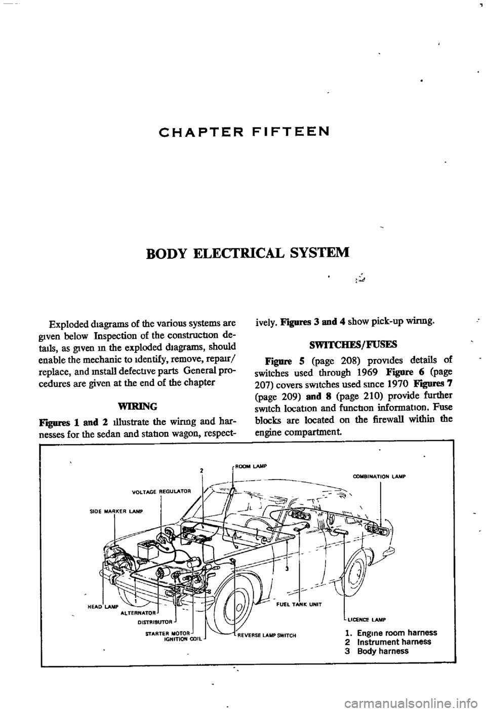
Exploded
diagrams
of
the
various
systems
are
given
below
Inspection
of
the
constructIon
de
tails
as
given
m
the
exploded
diagrams
should
enable
the
mechanic
to
Identify
remove
repauj
replace
and
mstall
defectIve
parts
General
pro
cedures
are
given
at
the
end
of
the
chapter
WIRING
FJgUres
1
and
2
illustrate
the
winng
and
har
nesses
for
the
sedan
and
statIon
wagon
respect
2
VOLTAGE
REGULATOR
JOE
MARKER
l
AMJ
STARTER
MOTOR
IGHITION
COIL
t
ively
Figures
3
and
4
show
pick
up
winng
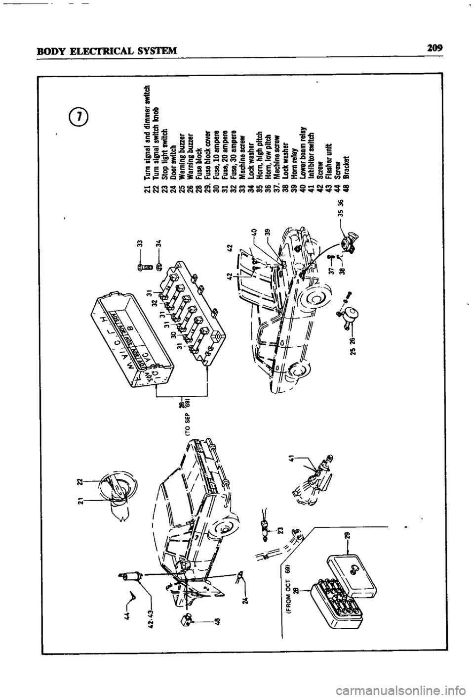
SWITCHES
FUSES
Figure
5
page
208
prOVides
details
of
switches
used
through
1969
Figure
6
page
207
covers
SWitches
used
smce
1970
FIgDI
eS
7
page
209
and
8
page
210
provide
further
SWitch
locatlon
and
fnnctIon
informatIon
Fuse
blocks
are
located
on
the
firewall
within
the
engine
compartment
ROOM
LAMP
COMBINATION
lAMP
LICENCE
lAMP
1
Engme
room
harness
2
Instrument
harness
3
Body
harness
Page 214 of 252
44
y
l
l
42
43
r
48
cr
23
41
f
Jj
it
d
F
1L
f7
IF
f
0
l
Q
U
lJ
37
1
2S
26
38
A
3S
36
G
21
Turn
signal
and
dimmer
switch
22
Turn
signal
switch
knob
23
Stop
light
switch
24
Door
switch
25
WarnIng
buzzer
26
Warning
buzzer
28
Fuse
block
29
Fuse
block
cover
30
Fuse
10
ampere
31
Fuse
20
ampere
32
Fuse
30
ampere
33
Machlnescrew
34
Lock
washer
35
Horn
hIgh
pitch
36
Horn
low
pitch
37
Machine
acrew
38
Lock
washer
39
Horn
relay
40
Lower
beem
relay
41
Inhibitor
switch
42
Screw
43
Flasher
unit
44
Screw
48
Bracket
o
i
Page 222 of 252

BODY
ELECTRICAL
SYSTEM
217
bulb
socket
must
be
pulled
out
from
the
back
of
the
unit
and
then
the
bulb
can
be
replaced
Care
fully
mspect
the
unit
that
reqUIres
bulb
replace
ment
and
follow
the
appropriate
procedure
Make
certain
you
replace
the
bulb
with
one
rated
at
the
same
voltage
amperage
and
watt
age
Examples
of
units
that
might
require
bulb
replacement
are
the
front
park
and
directional
lamps
rear
combination
lamp
side
marker
lamps
interior
room
lamps
license
plate
lamps
and
engine
compartment
lamps
Fuse
Replacement
Whenever
a
fallure
occurs
m
any
part
of
the
electrical
system
always
check
the
fuse
box
to
see
1f
a
fuse
has
blown
The
fuse
box
is
located
on
the
firewall
within
the
engine
compartment
If
a
fuse
has
blown
It
will
be
eVident
by
bIacken
mg
of
the
fuse
or
by
a
break
of
the
metal
element
Within
the
fuse
The
wiring
diagrams
below
mdIcate
the
cir
cuits
that
are
connected
to
each
fuse
Before
replacing
a
fuse
always
detenIlIDe
what
caused
it
to
blow
and
correct
the
trouble
Never
replace
a
fuse
With
one
of
a
higher
amperage
ratIng
than
originally
used
Never
use
tmfOll
or
other
ma
tenal
to
Jump
across
fuse
tenIlIDals
Failure
to
follow
these
basic
rules
could
result
in
fire
or
damage
to
major
components
WIRING
DIAGRAMS
The
following
figures
provide
wiring
diagrams
for
the
sedan
wagon
and
pick
up
Figure
20
page
220
applies
to
the
sedan
and
station
wagon
with
manual
transmission
Figure
21
page
221
covers
the
sedan
and
station
wagon
With
automatic
transmission
Figure
22
page
222
is
for
the
pick
up
I
Page 242 of 252
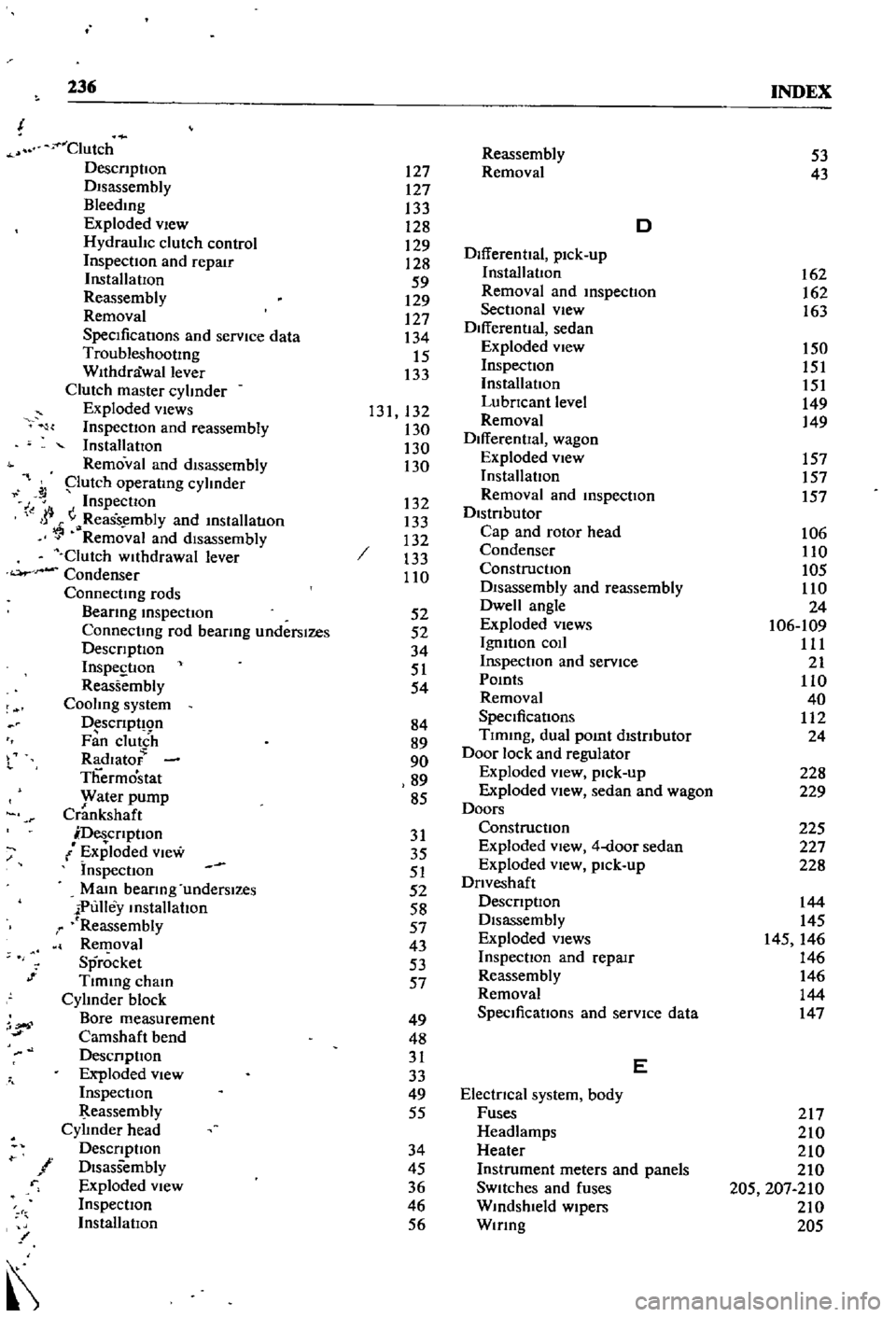
236
INDEX
Clutch
DescnptIon
DIsassembly
Bleedmg
Exploded
vIew
Hydraulic
clutch
control
InspectIOn
and
repair
InstallatIOn
Reassembly
Removal
SpecificatIons
and
service
data
TroubleshootIng
Withdrawal
lever
Clutch
master
cylinder
Exploded
views
InspectIon
and
reassembly
InstallatIOn
Removal
and
disassembly
putch
operatmg
cylinder
J
Inspection
I
jj
ReaSs
mbly
and
mslallatlOn
Removal
and
disassembly
Clutch
wllhdrawal
lever
Condenser
Connectmg
rods
Beanng
mspectIon
Connectmg
rod
bearmg
underslzes
DescrIptIOn
InspestIon
Reassembly
Cooling
system
D
scrIpt
Qn
Fan
clutch
Radlato
Thermostat
yvater
pump
Crankshaft
DescrIptIon
Exploded
View
Inspection
Mam
bearIng
underslzes
iPulley
mstallahon
r
Reassembly
Removal
Sprocket
Tlmmg
cham
Cylinder
block
Bore
measurement
Camshaft
bend
DesCrIpllOn
Exploded
view
InspectIOn
eassembly
Cylinder
head
DescrIptIon
f
DIsassembly
r
Exploded
View
InspectIOn
InstallatIOn
l
or
1
Reassembly
127
Removal
127
133
128
D
129
DifferentIal
pick
up
128
59
InstallatIon
129
Removal
and
mspecllOn
127
SectIOnal
view
134
Differential
sedan
15
Exploded
view
133
Inspection
InstallatIOn
131
132
LubrIcant
level
130
Removal
130
DifferentIal
wagon
130
Exploded
view
InstallatIon
132
Removal
and
mspecllon
133
DistrIbutor
132
Cap
and
rotor
head
133
Condenser
110
ConstructIon
DIsassembly
and
reassembly
52
Dwell
angle
52
Exploded
Views
34
IgmtIon
coIl
51
Inspection
and
service
54
Pomts
Removal
84
SpeCificatIons
89
Tlmmg
dual
pomt
distrIbutor
90
Door
lock
and
regulator
89
Exploded
view
pick
up
85
Exploded
View
sedan
and
wagon
Doors
31
Construction
35
Exploded
view
4
door
sedan
51
Exploded
vIew
pick
up
52
DrIveshaft
58
DescrIptIOn
57
Disassembly
43
Exploded
Views
53
InspectIon
and
repaIr
57
Reassembly
Removal
49
SpeCificatIons
and
service
data
48
31
E
33
49
ElectrIcal
system
body
55
Fuses
Headlamps
34
Heater
45
Instrument
meters
and
panels
36
SWitches
and
fuses
46
Wmdshleld
wipers
56
Wmng
53
43
162
162
163
150
151
151
149
149
157
157
157
106
110
105
110
24
106
109
111
21
110
40
112
24
228
229
225
227
228
144
145
145
146
146
146
144
147
217
210
210
210
205
207
210
210
205
Page 243 of 252
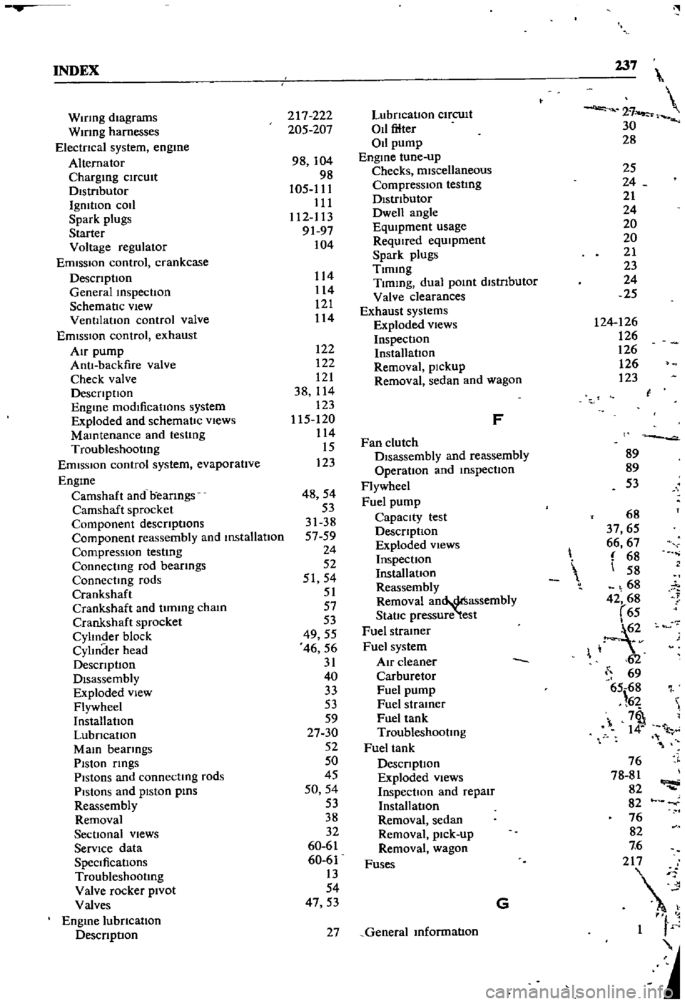
INDEX
237
2
7
30
28
WIrIng
diagrams
WIrIng
harnesses
Electncal
system
engme
Alternator
Chargmg
ClfCUlt
Dlstnbutor
IgmtlOn
coIl
Spark
plugs
Starter
Voltage
regulator
Emission
control
crankcase
DescnptIon
General
mspectIon
SchematIc
vIew
VentIlatIOn
control
valve
EmIssIOn
control
exhaust
AIr
pump
AntI
backfire
valve
Check
valve
DescnptlOn
Engme
modificatIons
system
Exploded
and
schematIc
vIews
Mamtenance
and
testIng
Troubleshootmg
Emission
control
system
evaporatIve
Engme
Camshaft
and
beanngs
Camshaft
sprocket
Component
descnptIons
Componenl
reassembly
and
mstallatIon
CompressIOn
testmg
Connectmg
rod
beanngs
Connectmg
rods
Crankshaft
Crankshaft
and
tImmg
cham
Crankshafl
sprocket
Cylmder
block
CylInder
head
DescnptlOn
Disassembly
Exploded
view
Flywheel
InstallatIOn
LubncatIon
MaIO
bearmgs
PIston
nngs
Pistons
and
connectmg
rods
PiStOns
and
piston
pms
Reassembly
Removal
SectIonal
views
ServIce
data
SpeCificatIons
Troubleshootmg
Valve
rocker
PIvot
Valves
Engme
lubncatlon
DescnptIon
217
222
205
207
98
104
98
105
111
111
112
113
9197
104
122
122
121
38
114
123
115
120
114
15
123
48
54
53
31
38
5759
24
52
51
54
51
57
53
49
55
46
56
31
40
33
53
59
27
30
52
50
45
50
54
53
38
32
60
61
60
61
13
54
47
53
114
114
121
114
LubncatlOn
ClfCUlt
011
filter
011
pump
Engme
tune
up
Checks
miscellaneous
Compression
testIng
DIstributor
Dwell
angle
EqUIpment
usage
ReqUIred
eqUIpment
Spark
plugs
Tlmmg
Tlmmg
dual
pomt
dlstnbutor
Valve
clearances
Exhaust
systems
Exploded
views
InspectIon
InstallatIOn
Removal
pickup
Removal
sedan
and
wagon
F
Fan
clutch
DIsassembly
and
reassembly
OperatIon
and
mspectlon
Flywheel
Fuel
pump
Capacity
test
DescnptlOn
Exploded
views
InspectIOn
InstallatIOn
Reassembly
Removal
an
assembly
StatIc
pressure
test
Fuel
stramer
Fuel
system
Air
cleaner
Carburetor
Fuel
pump
Fuel
stramer
Fuel
tank
Troubleshootmg
Fuel
tank
DescnptIon
Exploded
Views
InspectIOn
and
repaIr
Installation
Removal
sedan
Removal
pick
up
Removal
wagon
Fuses
G
27
General
mformatIon
25
24
21
24
20
20
21
23
24
25
124
126
126
126
126
123
l
89
89
53
68
37
65
66
67
68
58
68
42
68
65
1
2v
62
69
65
68
l
6
7
1
l
76
78
81
82
82
76
82
7
6
2
1
F