1968 DATSUN 510 bulb
[x] Cancel search: bulbPage 15 of 252

10
CHAPTER
THREE
pressure
bUllt
up
In
each
cylInder
The
readIngs
when
properly
Interpreted
IndIcate
general
cyl
Inder
and
valve
condltlOn
Vacuum
Gauge
The
vacuum
gauge
IS
easy
to
use
but
dIfficult
for
an
Inexpenenced
mechanIC
to
Interpret
The
results
when
conSIdered
WIth
other
findIngs
can
prOVIde
valuable
clues
to
pOSSIble
trouble
Connect
the
vacuum
gauge
WIth
a
T
connec
tIon
In
the
hose
from
the
carburetor
to
the
vacuum
advance
on
the
dIstnbutor
Start
the
engme
and
let
It
warm
up
thoroughly
Vacuum
readIng
should
be
steady
at
18
22
Inches
NOTE
Subtract
1
Inch
from
reading
for
every
1000
feet
of
altitude
Figure
1
shows
numerous
tYPical
readIngs
WIth
InterpretatIons
Results
are
not
conclusive
WIthout
companng
to
other
tests
such
as
com
preSSIOn
readIngs
Fuel
Pressure
Gauge
ThIS
Instrument
IS
VItal
for
evaluatIng
fuel
pump
performance
Often
a
vacuum
gauge
and
fuel
pressure
gauge
are
combIned
Dwell
Meter
A
dwell
meter
measures
the
dIstance
In
de
grees
of
cam
rotatIon
that
the
breaker
pOInts
remaIn
closed
while
the
engme
IS
runnIng
SInce
thIS
angle
IS
determmed
by
breaker
pOInt
gap
the
dwell
angle
IS
an
accurate
IndIcatIon
of
pOInt
gap
Many
tachometers
Intended
for
tunIng
and
testIng
Incorporate
a
dwell
meter
as
well
Follow
the
manufacturer
s
InstructIon
to
measure
dwell
on
the
Datsun
Tachometer
A
tachometer
IS
essential
for
tunIng
Datsuns
WIth
exhaust
emission
control
deVices
IgmtIOn
turung
and
carburetor
adjustments
must
be
per
formed
at
the
specified
Idle
speed
The
best
In
strument
for
thIS
purpose
IS
one
WIth
a
range
of
0
1
000
or
0
2
000
rpm
Extended
range
0
6
000
or
8
000
Instruments
lack
accuracy
at
lower
speeds
The
InStrument
should
be
capable
of
detecting
changes
of
25
rpm
Stroboscopic
Timing
Light
ThIS
Instrument
pernuts
accurate
IgnitIon
tImIng
By
f1ashmg
a
bght
at
the
preCISe
Instant
cylInder
No
1
fires
the
posItIon
of
the
crank
shaft
pulley
at
that
Instant
can
be
seen
Marks
on
the
pulley
bne
up
With
a
reference
pOInter
on
the
block
dunng
the
tIming
procedure
SUltable
bghts
are
neon
bulb
types
and
xenon
strobe
hghts
Neon
tunmg
bghts
are
ddticult
to
see
and
must
be
used
in
dImly
bt
areas
Xenon
strobe
bghts
can
be
used
In
bnght
sunbght
Use
the
bght
accordIng
to
the
manufacturer
s
InStruC
tIons
Exhaust
Analyzer
Of
all
Instruments
descnbed
here
this
IS
the
least
bkely
to
be
owned
by
a
home
mechanic
One
Instrument
samples
the
exhaust
gases
from
the
taIlpIpe
and
measures
the
thermal
conduc
tIVIty
of
the
exhaust
gas
SInce
different
gases
conduct
heat
at
varYIng
rates
thermal
conduc
tIVIty
of
the
exhaust
IS
a
good
IndIcatIon
of
gases
present
This
Instrument
IS
VItal
for
accurately
checkIng
the
effectIveness
of
exhaust
emIssion
control
adjustments
but
IS
too
expenSIve
for
an
amateur
mechanIC
to
conSIder
buying
STARTER
Starter
system
troubles
are
relatIvely
easy
to
ISolate
The
followmg
are
common
symptoms
and
cures
1
Engme
cranks
very
slowly
or
not
at
all
Turn
on
the
headhghts
If
the
bghts
are
very
dun
most
likely
the
battery
or
the
connecting
WireS
are
at
fault
Check
the
battery
using
the
pro
cedures
descnbed
in
the
Tune
up
chapter
Check
wmmgfur
e
s
wom
andd
connectIom
H
the
battery
and
connectIng
WIres
check
good
turn
the
headlIghts
on
and
try
to
crank
the
engIne
H
the
lIghts
dIDl
drastIcally
the
starter
is
probably
shorted
to
ground
Remove
the
starter
and
test
it
usmg
the
procedures
gIven
in
Chapter
NIne
If
the
lights
remain
bnght
or
dun
slIghtly
when
crankIng
the
engme
the
trouble
may
be
in
the
starter
solenOId
or
wmng
To
ISolate
the
trouble
short
the
two
large
solenoid
ternunals
together
not
to
ground
if
the
starter
cranks
normally
check
the
solenoid
and
wmng
up
to
the
Page 153 of 252

148
CHAPTER
ELEVEN
1
Insert
key
in
IgnItion
switch
and
turn
to
first
posltlon
2
Depress
accelerator
pedal
fully
LISten
for
the
solenOId
to
click
If
a
clIck
is
heard
the
solenoid
is
operating
correctly
3
Replace
solenoid
if
click
IS
not
heard
Before
replacing
solenoid
dram
apprOlumately
2
pInts
of
transmission
011
from
tranSmISsion
Re
fill
when
solenoid
replacement
is
complete
4
If
solenoId
IS
operatlng
correctly
but
trouble
persISts
check
WIres
for
continuity
With
electri
cal
tester
Linkage
Inspection
and
Adjustment
To
inspect
and
adjust
the
linkage
on
the
transmission
proceed
as
follows
Figure
4
j
shows
the
linkage
for
column
shift
models
and
Figure
47
shows
the
lInkage
for
floor
shift
models
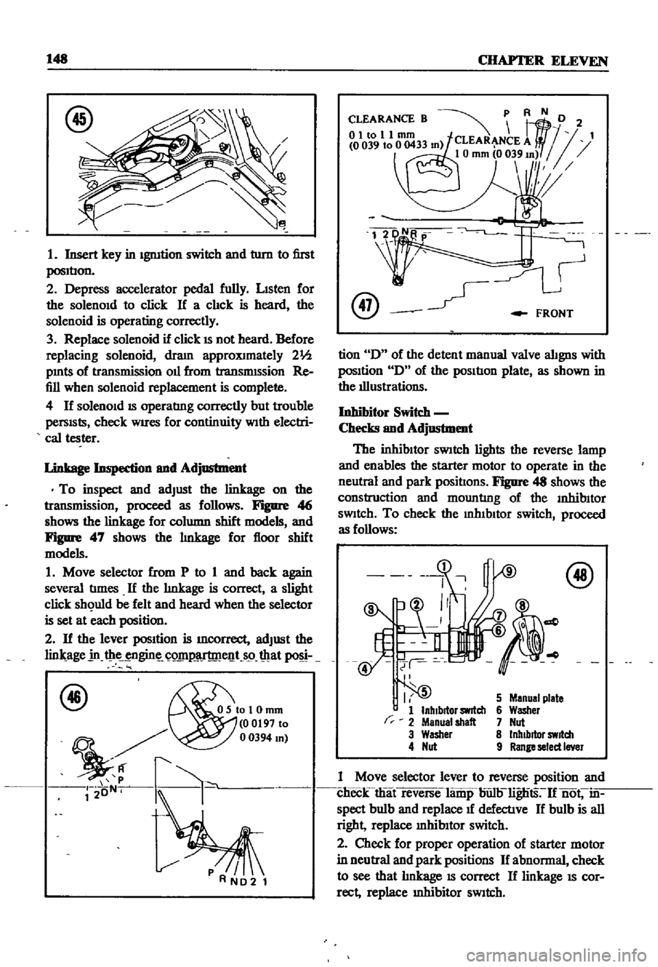
1
Move
selector
from
P
to
1
and
back
again
several
tImes
If
the
lInkage
is
correct
a
slight
click
sh
uld
be
felt
and
heard
when
the
selector
is
set
at
each
position
2
If
the
lever
position
is
mcorrect
adjust
the
lin
age
in
t
ie
ngin
C
Q1I1
lT
me
t
s9
mat
f46
OSIoI0mm
00197
to
mJ
r2
oN
k
@
FRONT
tion
D
of
the
detent
manual
valve
alignS
with
posItion
D
of
the
pOSItIon
plate
as
shown
in
the
illustrations
Inhibitor
Switc
h
Checks
and
Adjustment
The
inhibItor
SWitch
lights
the
reverse
lamp
and
enables
the
starter
motor
to
operate
in
the
neutral
and
park
positIons
Figure
48
shows
the
construction
and
mountlng
of
the
InhibItor
SWitch
To
check
the
mhIbltor
switch
proceed
as
follows
r
I
5
1
InhIbitor
switch
2
Menual
shalt
3
Washer
4
Nut
5
Manual
plate
6
Washer
7
Nut
8
Inhibitor
switch
9
Range
select
Iner
1
Move
selector
lever
to
reverse
position
and
clieck
that
reverse
lamp
bun
lignts
If
not
in
spect
bulb
and
replace
1f
defectlve
If
bulb
is
all
right
replace
mhibItor
switch
2
Check
for
proper
operation
of
starter
motor
in
neutral
and
park
positions
If
abnormal
check
to
see
that
lInkage
IS
correct
If
linkage
IS
cor
rect
replace
Inhibitor
SWitch
Page 190 of 252

NP
BRAND
3536
48
47
49
UP
TO
SEP
69
15
10
l
f
J
r
1
L
IZM
BRAND
39
39
AUTOMATIC
2
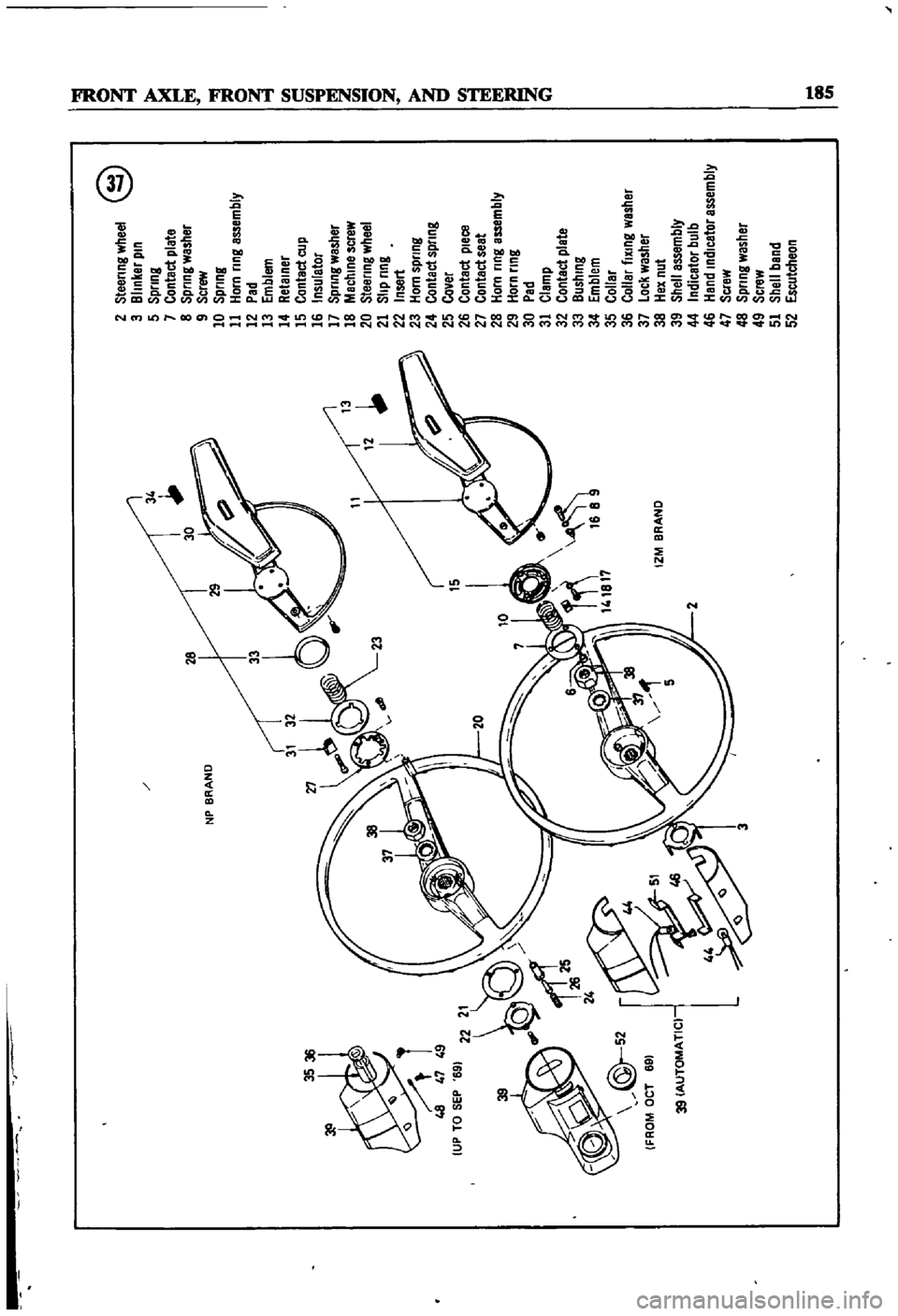
Steering
wheel
@
3
Blinker
pin
5
Spring
7
Contact
plate
8
Spring
washer
9
Screw
10
Spring
11
Horn
ring
assembly
12
Pad
13
Emblem
14
Retainer
15
Contact
cup
16
Insulator
17
Spring
washer
18
Machine
screw
20
Steering
wheel
21
Slip
ring
22
Insert
23
Horn
spring
24
Contact
spring
25
Cover
26
Contact
pleca
27
Contact
seat
28
Horn
ring
assembly
29
Horn
ring
30
Pad
31
Clamp
32
Contact
plate
33
Bushing
34
Emblem
35
Collar
36
Collar
fiXing
washer
37
Lock
washer
38
Hex
nut
39
Shell
assembly
44
Indicator
bulb
46
Hand
indicator
assembly
47
Scraw
48
Spring
washer
49
Screw
51
Shell
band
52
Escutcheon
o
I
l
I
l
i
J
I
Ci
l
QD
II
L
Page 215 of 252

110
CHAPTER
FIFTEEN
FOR
MANUAL
IGNITION
KEY
i
I
MADV
Nf
D
BRAKE
POINT
v
sa
tS
57
51
Th
rottle
sWItch
52
Speed
sWItch
relay
53
Speed
detector
assembly
Q
FOR
AUTOMATIC
IGNITION
KEY
AOVANEO
BRAKE
POINT
I
SPEED
DETECTOR
SPEED
SWITCH
I
RELAY
MJsr
I
IQ
52
SOLENOID
VALVE
54
Relay
55
Screw
56
Clutch
sWItch
assembly
57
Relay
assembly
58
Screw
INSTRUMENT
METERS
AND
PANELS
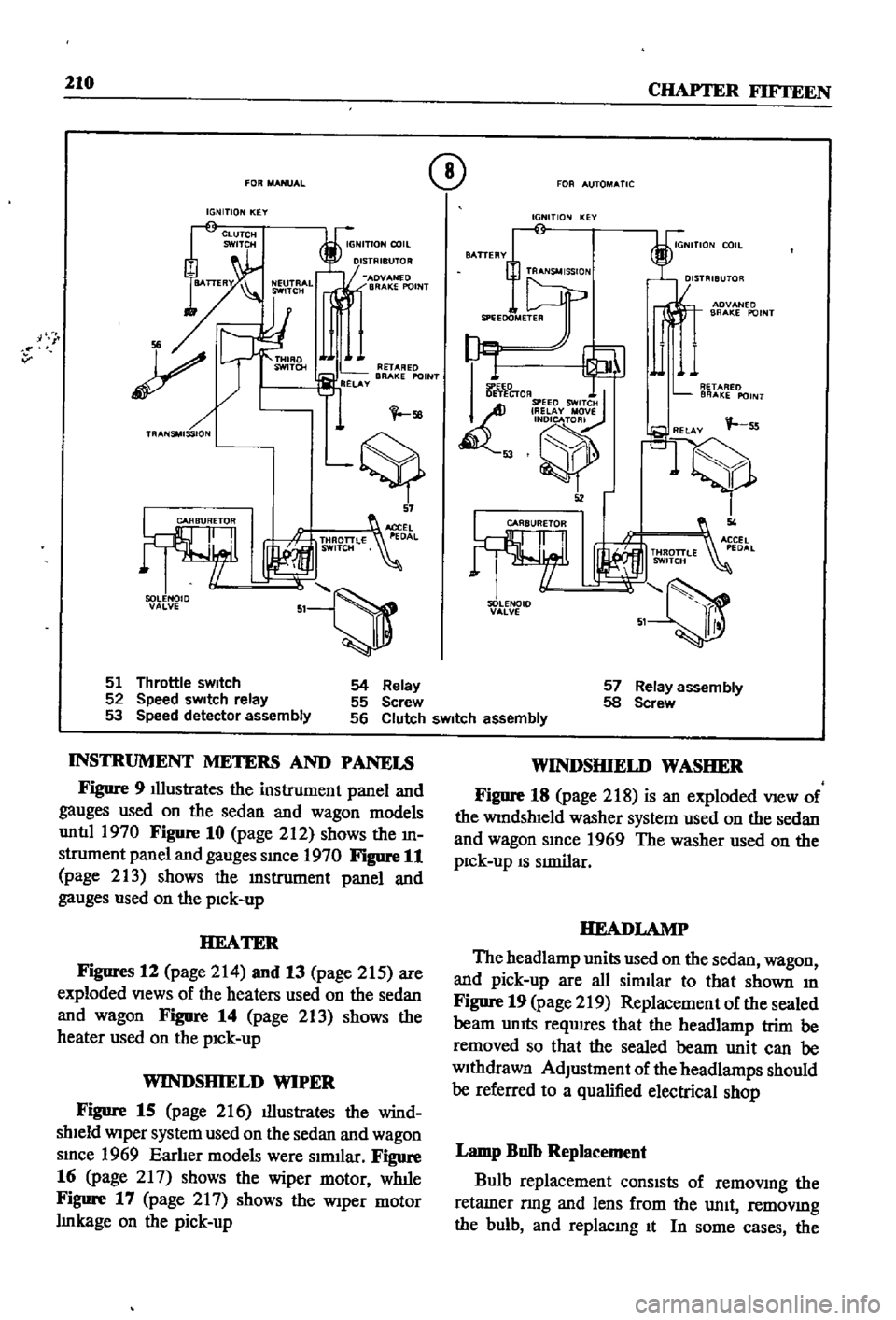
Figure
9
Illustrates
the
instrument
panel
and
gauges
used
on
the
sedan
and
wagon
models
untIl
1970
Figure
10
page
212
shows
the
m
strument
panel
and
gauges
smce
1970
Figure
11
page
213
shows
the
lDstrument
panel
and
gauges
used
on
the
pick
up
HEATER
Figures
12
page
214
and
13
page
215
are
exploded
Views
of
the
heaters
used
on
the
sedan
and
wagon
FigDre
14
page
213
shows
the
heater
used
on
the
pick
up
WINDSHIELD
WIPER
Figure
15
page
216
illustrates
the
wind
shield
Wiper
system
used
on
the
sedan
and
wagon
smce
1969
Earlier
models
were
slrmlar
Figure
16
page
217
shows
the
wiper
motor
wlule
Figure
17
page
2
I
7
shows
the
Wiper
motor
Imkage
on
the
pick
up
WINDSHIELD
WASHER
Figure
18
page
218
is
an
exploded
View
of
the
WindshIeld
washer
system
used
on
the
sedan
and
wagon
smce
1969
The
washer
used
on
the
pick
up
IS
SImilar
HEADLAMP
The
headlamp
units
used
on
the
sedan
wagon
and
pick
up
are
all
similar
to
that
shown
m
Figure
19
page
219
Replacement
of
the
sealed
beam
UnIts
reqwres
that
the
headlamp
trim
be
removed
so
that
the
sealed
beam
unit
can
be
withdrawn
AdJustment
of
the
headlamps
should
be
referred
to
a
qualified
electrical
shop
Lamp
Bulb
Replacement
Bulb
replacement
consIsts
of
removmg
the
retamer
nng
and
lens
from
the
unit
removmg
the
bulb
and
replacmg
It
In
some
cases
the
Page 222 of 252

BODY
ELECTRICAL
SYSTEM
217
bulb
socket
must
be
pulled
out
from
the
back
of
the
unit
and
then
the
bulb
can
be
replaced
Care
fully
mspect
the
unit
that
reqUIres
bulb
replace
ment
and
follow
the
appropriate
procedure
Make
certain
you
replace
the
bulb
with
one
rated
at
the
same
voltage
amperage
and
watt
age
Examples
of
units
that
might
require
bulb
replacement
are
the
front
park
and
directional
lamps
rear
combination
lamp
side
marker
lamps
interior
room
lamps
license
plate
lamps
and
engine
compartment
lamps
Fuse
Replacement
Whenever
a
fallure
occurs
m
any
part
of
the
electrical
system
always
check
the
fuse
box
to
see
1f
a
fuse
has
blown
The
fuse
box
is
located
on
the
firewall
within
the
engine
compartment
If
a
fuse
has
blown
It
will
be
eVident
by
bIacken
mg
of
the
fuse
or
by
a
break
of
the
metal
element
Within
the
fuse
The
wiring
diagrams
below
mdIcate
the
cir
cuits
that
are
connected
to
each
fuse
Before
replacing
a
fuse
always
detenIlIDe
what
caused
it
to
blow
and
correct
the
trouble
Never
replace
a
fuse
With
one
of
a
higher
amperage
ratIng
than
originally
used
Never
use
tmfOll
or
other
ma
tenal
to
Jump
across
fuse
tenIlIDals
Failure
to
follow
these
basic
rules
could
result
in
fire
or
damage
to
major
components
WIRING
DIAGRAMS
The
following
figures
provide
wiring
diagrams
for
the
sedan
wagon
and
pick
up
Figure
20
page
220
applies
to
the
sedan
and
station
wagon
with
manual
transmission
Figure
21
page
221
covers
the
sedan
and
station
wagon
With
automatic
transmission
Figure
22
page
222
is
for
the
pick
up
I
Page 244 of 252

138
INDEX
H
OIl
pump
Descnptlon
36
Handbrake
Exploded
view
29
Adjustment
202
Inspection
and
repaIr
28
Cable
removal
front
sedan
and
wagon
197
Installation
58
Cable
removal
rear
pick
up
201
Removal
28
40
Cable
removal
rear
sedan
and
wagon
197
Cross
rod
removal
wagon
201
Exploded
views
198
200
p
Inspection
and
repair
201
Installation
201
Penodlc
mamtenance
Headlights
MaIntenance
mtervals
chart
7
Bulb
replacement
210
Penodlc
checks
6
Descnptlon
210
Recommended
lubncants
8
Exploded
view
219
Routine
checks
6
HeatIng
system
Piston
nngs
Descnptlon
210
Exploded
view
pick
up
213
Inspection
50
Exploded
VIews
sedan
and
wagon
214
215
Removal
45
Hood
lock
control
RIng
gap
50
Exploded
View
pick
up
225
Pistons
Descnptlon
34
Exploded
VIew
sedan
and
wagon
226
Inspection
50
Reassembly
54
Igmtlon
coil
111
R
Igmtlon
system
Tlmmg
23
Radiator
Troubleshooting
13
Exploded
view
90
Instrument
meters
and
panels
Removal
and
replacement
90
Descnptlon
210
Rear
axle
pick
up
Exploded
View
pick
up
213
Axle
case
166
Exploded
view
sedan
and
wagon
Inspection
and
mstalIatlon
164
1970
1972
212
Removal
164
Exploded
view
sedan
and
wagon
Sectional
view
163
through
1969
211
Rear
axle
wagon
Intake
manifold
Disassembly
158
Descnptlon
36
Exploded
view
158
Removal
42
Inspection
and
reassembly
160
InstallatIOn
160
Removal
158
M
Rear
axle
and
suspenSion
sedan
Exploded
view
152
153
Mam
beanngs
52
Inspection
and
repaIr
154
MaIntenance
penodlc
6
8
InstalIatlon
154
Master
cylInder
Removal
151
Exploded
vIew
smgle
188
Rear
spnngs
pick
up
166
Exploded
view
tandem
189
Rear
spnngs
wagon
161
Inspection
and
repllIr
188
Rear
axle
shaft
sedan
155
156
Reassembly
and
InstalIatlon
190
Rear
suspension
arm
sedan
155
Removal
and
disassembly
188
Rear
suspenSion
pick
up
Modelldentdicatlon
1
Exploded
view
166
Inspection
and
repllIr
167
InstalIatlon
167
0
Rear
spnngs
166
Removal
165
011
filler
30
Spnngs
166
d
43
Torques
67