1968 DATSUN 510 gas type
[x] Cancel search: gas typePage 14 of 252

CHAPTER
THREE
TROUBLESHOOTING
TroubleshootIng
the
Datsun
can
be
relatlvely
simple
1f
done
lOgically
The
first
step
must
always
be
to
define
symptoms
as
closely
as
pos
Sible
Subsequent
steps
mvolve
testIng
and
an
alyzmg
areas
which
could
cause
the
symptoms
Procedures
m
thiS
chapter
analyze
typical
symp
toms
and
give
lOgical
methods
of
isolation
These
are
not
the
only
methods
There
may
be
several
approaches
to
solvmg
a
problem
but
all
must
have
one
thmg
m
common
a
lOgical
systematic
approach
TROUBLESHOOTING
EQUIPMENT
The
followmg
eqUipment
is
necessary
to
prop
erly
troubleshoot
an
engme
1
Voltmeter
Ammeter
and
Ohmmeter
2
Hydrometer
3
Compression
Tester
4
Vacuum
Gauge
5
Fuel
Pressure
Gauge
6
Dwell
Meter
7
Tachometer
8
StroboscopiC
Trming
Light
9
Exhaust
Gas
Analyzer
Items
1
through
8
are
essentlal
Item
9
is
necessary
for
exhaust
elDlSSion
control
comph
ance
The
followmg
is
a
bnef
description
of
the
functlon
of
each
mstrument
Voltmeter
Ammeter
and
Ohmmeter
For
testIng
the
ignitlon
and
electncal
systems
a
good
voltmeter
is
reqUIred
For
automotIve
use
an
mstrument
covenng
0
20
volts
is
salls
factory
It
should
have
an
accuracy
of
about
Ih
volt
which
excludes
the
common
auto
moUve
type
found
in
instrument
panels
An
ohmmeter
measures
electncal
reSiStance
and
is
reqUired
to
check
electncal
contInUity
open
and
short
circwts
and
for
testing
fuses
and
hghts
The
ammeter
measures
electncal
current
One
for
automotIve
use
should
cover
0
10
and
0
100
amperes
An
ammeter
is
useful
for
checkmg
bat
tery
chargmg
and
startIng
current
The
starter
and
generator
procedures
m
tlus
manual
use
an
ammeter
to
check
for
shorted
wmdmgs
Several
inexpensive
VOM
s
volt
ohmmeters
combme
all
mstruments
and
fit
easily
mto
any
tool
box
The
ammeter
ranges
are
often
too
small
for
auto
motIve
work
thougll
Hydrometer
A
hydrometer
is
necessary
to
check
battery
condition
and
charge
It
measures
specific
grav
ity
of
the
electrolyte
in
each
cell
Compression
Tester
The
compressiOn
tester
measures
compression
Page 15 of 252

10
CHAPTER
THREE
pressure
bUllt
up
In
each
cylInder
The
readIngs
when
properly
Interpreted
IndIcate
general
cyl
Inder
and
valve
condltlOn
Vacuum
Gauge
The
vacuum
gauge
IS
easy
to
use
but
dIfficult
for
an
Inexpenenced
mechanIC
to
Interpret
The
results
when
conSIdered
WIth
other
findIngs
can
prOVIde
valuable
clues
to
pOSSIble
trouble
Connect
the
vacuum
gauge
WIth
a
T
connec
tIon
In
the
hose
from
the
carburetor
to
the
vacuum
advance
on
the
dIstnbutor
Start
the
engme
and
let
It
warm
up
thoroughly
Vacuum
readIng
should
be
steady
at
18
22
Inches
NOTE
Subtract
1
Inch
from
reading
for
every
1000
feet
of
altitude
Figure
1
shows
numerous
tYPical
readIngs
WIth
InterpretatIons
Results
are
not
conclusive
WIthout
companng
to
other
tests
such
as
com
preSSIOn
readIngs
Fuel
Pressure
Gauge
ThIS
Instrument
IS
VItal
for
evaluatIng
fuel
pump
performance
Often
a
vacuum
gauge
and
fuel
pressure
gauge
are
combIned
Dwell
Meter
A
dwell
meter
measures
the
dIstance
In
de
grees
of
cam
rotatIon
that
the
breaker
pOInts
remaIn
closed
while
the
engme
IS
runnIng
SInce
thIS
angle
IS
determmed
by
breaker
pOInt
gap
the
dwell
angle
IS
an
accurate
IndIcatIon
of
pOInt
gap
Many
tachometers
Intended
for
tunIng
and
testIng
Incorporate
a
dwell
meter
as
well
Follow
the
manufacturer
s
InstructIon
to
measure
dwell
on
the
Datsun
Tachometer
A
tachometer
IS
essential
for
tunIng
Datsuns
WIth
exhaust
emission
control
deVices
IgmtIOn
turung
and
carburetor
adjustments
must
be
per
formed
at
the
specified
Idle
speed
The
best
In
strument
for
thIS
purpose
IS
one
WIth
a
range
of
0
1
000
or
0
2
000
rpm
Extended
range
0
6
000
or
8
000
Instruments
lack
accuracy
at
lower
speeds
The
InStrument
should
be
capable
of
detecting
changes
of
25
rpm
Stroboscopic
Timing
Light
ThIS
Instrument
pernuts
accurate
IgnitIon
tImIng
By
f1ashmg
a
bght
at
the
preCISe
Instant
cylInder
No
1
fires
the
posItIon
of
the
crank
shaft
pulley
at
that
Instant
can
be
seen
Marks
on
the
pulley
bne
up
With
a
reference
pOInter
on
the
block
dunng
the
tIming
procedure
SUltable
bghts
are
neon
bulb
types
and
xenon
strobe
hghts
Neon
tunmg
bghts
are
ddticult
to
see
and
must
be
used
in
dImly
bt
areas
Xenon
strobe
bghts
can
be
used
In
bnght
sunbght
Use
the
bght
accordIng
to
the
manufacturer
s
InStruC
tIons
Exhaust
Analyzer
Of
all
Instruments
descnbed
here
this
IS
the
least
bkely
to
be
owned
by
a
home
mechanic
One
Instrument
samples
the
exhaust
gases
from
the
taIlpIpe
and
measures
the
thermal
conduc
tIVIty
of
the
exhaust
gas
SInce
different
gases
conduct
heat
at
varYIng
rates
thermal
conduc
tIVIty
of
the
exhaust
IS
a
good
IndIcatIon
of
gases
present
This
Instrument
IS
VItal
for
accurately
checkIng
the
effectIveness
of
exhaust
emIssion
control
adjustments
but
IS
too
expenSIve
for
an
amateur
mechanIC
to
conSIder
buying
STARTER
Starter
system
troubles
are
relatIvely
easy
to
ISolate
The
followmg
are
common
symptoms
and
cures
1
Engme
cranks
very
slowly
or
not
at
all
Turn
on
the
headhghts
If
the
bghts
are
very
dun
most
likely
the
battery
or
the
connecting
WireS
are
at
fault
Check
the
battery
using
the
pro
cedures
descnbed
in
the
Tune
up
chapter
Check
wmmgfur
e
s
wom
andd
connectIom
H
the
battery
and
connectIng
WIres
check
good
turn
the
headlIghts
on
and
try
to
crank
the
engIne
H
the
lIghts
dIDl
drastIcally
the
starter
is
probably
shorted
to
ground
Remove
the
starter
and
test
it
usmg
the
procedures
gIven
in
Chapter
NIne
If
the
lights
remain
bnght
or
dun
slIghtly
when
crankIng
the
engme
the
trouble
may
be
in
the
starter
solenOId
or
wmng
To
ISolate
the
trouble
short
the
two
large
solenoid
ternunals
together
not
to
ground
if
the
starter
cranks
normally
check
the
solenoid
and
wmng
up
to
the
Page 26 of 252

ENGINE
AND
IGNITION
TUNE
UP
21
many
types
of
test
eqUipment
and
may
be
used
as
a
gUide
If
the
manufacturer
s
mstructioQs
are
not
aVailable
Connections
shown
in
Figure
1
are
as
follows
1
Voltmeter
a
PosItive
lead
to
resistor
side
of
COli
b
Negative
1
ead
to
ground
2
Tlmmg
Light
a
PosItive
lead
to
posItive
battery
termmal
b
Tngger
lead
to
number
1
spark
plug
c
Negative
lead
to
ground
3
Tachometer
a
PosItive
lead
to
dlstnbutor
Side
of
coil
b
Negative
lead
to
ground
4
Dwell
Meter
a
PosItive
lead
to
dlstnbutor
Side
of
COlI
b
Negative
lead
to
ground
BAlTERY
INSPECTION
AND
SERVICE
1
Check
the
level
of
the
electrolyte
m
battery
cells
If
necessary
replemsh
with
distilled
water
Do
not
overfill
2
Measure
the
speCific
gravity
of
the
battery
electrolyte
Refer
to
the
followmg
table
2
Use
the
proper
size
socket
and
wrench
to
remove
spark
plugs
from
the
cyhnder
head
Make
certam
that
the
gaskets
are
removed
from
the
spark
plug
holes
3
Wipe
off
the
msulator
With
a
clean
rag
to
remove
grease
and
dirt
4
Carefully
mspect
the
msulator
and
body
of
each
plug
for
signs
of
cracks
or
chips
Replace
If
faulty
5
Inspect
spark
plug
threads
and
electrodes
for
damage
or
excessive
wear
Replace
as
requrred
Figure
2
shows
the
cond1t
J
on
of
normal
and
de
fectIVe
spark
plugs
along
with
an
explanation
of
the
causes
of
the
abnormal
conditions
6
If
the
spark
plugs
are
still
serviceable
clean
them
thoroughly
With
a
stiff
brush
or
preferably
With
a
sand
blasting
type
of
cleaner
7
File
the
center
electrode
so
that
It
has
a
fiat
surface
8
File
the
surfaces
of
the
outer
electrode
so
that
all
surfaces
are
fiat
and
smooth
9
Usmg
a
feeler
gauge
adjust
clearance
be
tween
the
electrodes
to
0
031
to
0
035
m
0
8
to
0
9mm
as
shown
m
Figure
3
Full
Charge
Value
CD
68
degrees
F
PermiSSIble
Value
20
degrees
C
3
Frigid
chmates
Tropical
chmates
Other
climates
Over
1
22
Over
118
Over
1
20
128
123
126
3
Clean
top
of
battery
and
termmals
With
a
solutIOn
of
bakmg
soda
and
water
Rmse
off
and
dry
thoroughly
Top
of
battery
must
be
clean
to
prevent
current
leakage
between
termmal
and
from
pOSitive
termmal
to
hold
down
clamp
Pro
longed
accumulatIOn
of
aCid
and
dirt
on
top
of
battery
may
cause
blIstenng
of
the
matenal
cov
enng
on
the
connector
straps
and
detenoration
of
the
straps
themselves
4
Tighten
the
cable
connectors
to
the
termmal
securely
5
Coat
the
termmals
lIghtly
With
petrolatum
to
protect
them
from
corrosion
SPARK
PLUGS
INSPECTION
AND
SERVICE
1
Remove
spark
plug
WIres
Mark
them
to
fi
sure
correct
replacement
J
J
I
I
j
j
10
Remstall
spark
plugs
Make
certam
to
use
a
new
gasket
for
each
plug
Use
a
torque
wrench
to
tighten
spark
plugs
from
11
0
to
150
ft
lb
1
5
to
2
0
kg
m
11
Remstall
WIres
DISTRIBUTOR
INSPECTION
AND
SERVICE
Dependmg
on
the
model
year
velucles
have
a
smgle
pomt
or
a
dual
pomt
dlstnbutor
system
Page 35 of 252

30
CHAPTER
FIVE
should
be
1
54
m
39mm
If
the
spnng
tension
is
accurate
the
rehef
valve
should
open
at
54
0
to
59
7
lb
1m
3
8
to
4
2
kg
cm
6
Reassemble
the
oil
pump
Make
certain
all
gaskets
are
mounted
flat
to
avoid
leaks
7
Install
the
dnve
spindle
and
the
oil
pump
to
the
front
cover
8
Install
the
distnbutor
in
the
same
relative
locallon
from
which
it
was
removed
If
the
num
ber
1
cyhnder
was
at
top
dead
center
on
the
compression
stroke
the
punch
mark
on
the
dnve
spindle
should
face
toward
the
front
of
the
engine
9
Install
the
front
splash
shield
and
the
front
stablhzer
10
Insert
the
drain
plug
in
the
pan
and
refill
the
engme
11
Oil
pressure
at
idle
should
be
142
to
17
1
lb
lin
1
0
to
1
2
kg
cm
12
Tlghtenmg
torque
values
for
the
oil
pump
mounting
bolts
is
10
8
to
152ft
lb
1
5
to
2
1
kg
m
and
21
69
to
25
31
ft
lb
3
0
to
25
kg
m
for
the
release
valve
cap
nut
Oil
Filter
The
oil
filter
is
mounted
on
the
nght
hand
side
of
the
cyhnder
block
It
IS
a
cartndge
type
with
built
m
gasket
and
threads
onto
the
mounting
spindle
The
filter
should
be
replaced
every
6
000
miles
as
follows
1
Dram
the
engme
oil
Walt
10
15
minutes
before
removmg
oil
filter
to
allow
It
to
dram
2
By
hand
or
with
the
aid
of
an
oil
filter
wrench
unscrew
the
filter
from
the
spmdle
as
shown
m
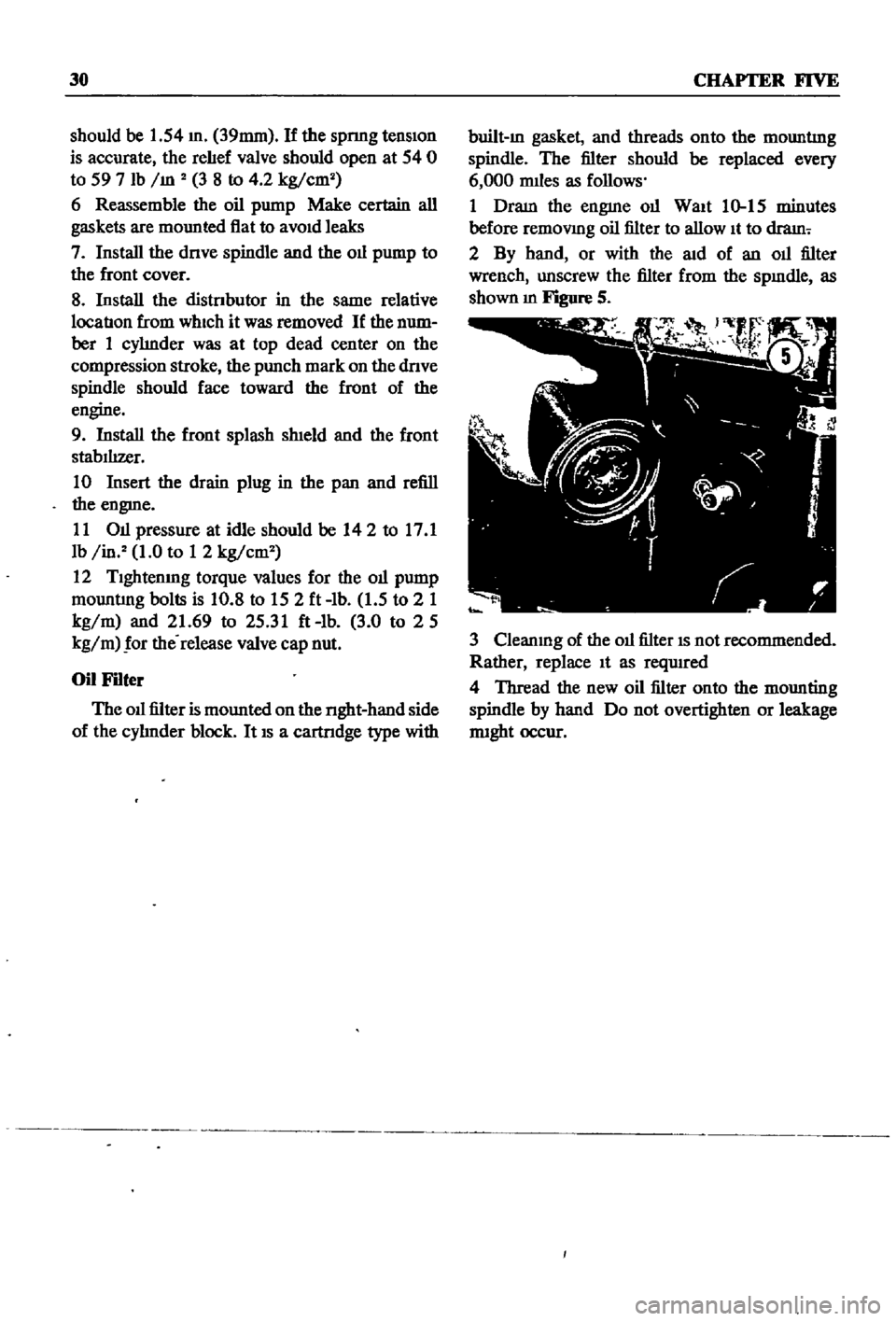
Figure
S
3
Cleanmg
of
the
oil
filter
IS
not
recommended
Rather
replace
It
as
reqUIred
4
Thread
the
new
oil
filter
onto
the
mounting
spindle
by
hand
Do
not
overtighten
or
leakage
nught
occur
Page 41 of 252

36
CHAPTER
SIX
0B
34
35
2224
19
21
p
7
31
13
4
7
O
41
rlj
17
11
lOlL
JET
2
Intake
valve
Insert
3
Exhaust
valve
Insert
4
Intake
valve
guide
5
Exhaust
valve
guide
3
2
7
Od
gallery
taper
plug
I
441
J
8
Cylinder
blind
plug
9
Cylinder
blind
plug
10
Taper
plug
21
Washer
34
Rocker
cover
44
Spnng
washer
11
Cylinder
head
011
jet
22
Front
head
cover
35
Rocker
cover
gasket
45
Water
outlet
12
stud
23
Bolt
36
Od
filler
cap
46
JOint
washer
13
stud
24
Front
cover
head
gasket
37
011
cap
paclung
47
stud
14
stud
28
Hex
bolt
38
Rocker
cover
bolt
48
Hex
nut
15
Stud
29
lock
washer
spring
39
Thennostat
a5sem
bly
49
Spring
washer
17
Cylinder
head
gasket
30
Engine
front
Slinger
40
Thennostat
hOUSing
50
Water
temperature
gauge
18
Cylinder
head
bolt
31
Engine
rear
slinger
41
Thennostat
gasket
51
Water
temperature
ground
nut
19
Cylinder
head
bolt
32
Spnng
washer
42
Hex
bolt
53
Cam
bracket
bolt
20
Cylinder
head
bolt
33
Hex
nut
43
Hex
bolt
54
Cam
bracket
bolt
shoe
type
of
tensIOner
reduces
vibration
and
controls
overall
cham
tenSIOn
MANIFOLDS
The
intake
and
exhaust
manifolds
are
shown
in
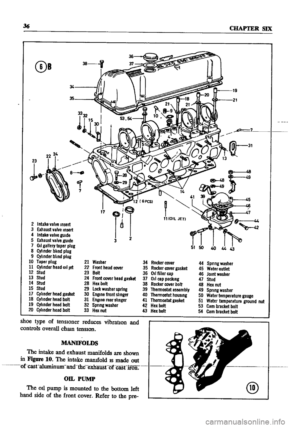
Figure
10
The
intake
mamfold
IS
made
out
of
cast
aluminum
and
the
eXhaustof
casn
roir
OIL
PUMP
The
oil
pump
is
mounted
to
the
bottom
left
hand
side
of
the
front
cover
Refer
to
the
pre
@
Page 61 of 252

56
CHAPTER
SIX
NOTE
Lubncate
the
cylinder
walls
with
new
engine
oil
prior
to
insertIOn
of
pistOns
Make
certain
that
the
ring
gaps
are
not
In
line
wIth
one
another
Place
the
gaps
180
degrees
from
each
other
and
not
posltloned
either
front
to
back
or
dIrectly
in
line
with
the
piston
pIns
CAUTION
Use
extreme
care
when
Inserting
pzs
tons
so
as
to
avoId
crankshaft
damage
14
With
the
aid
of
a
nng
compressor
illStaIl
the
pISton
and
connectmg
rod
assembhes
into
the
cyhnder
block
as
shown
in
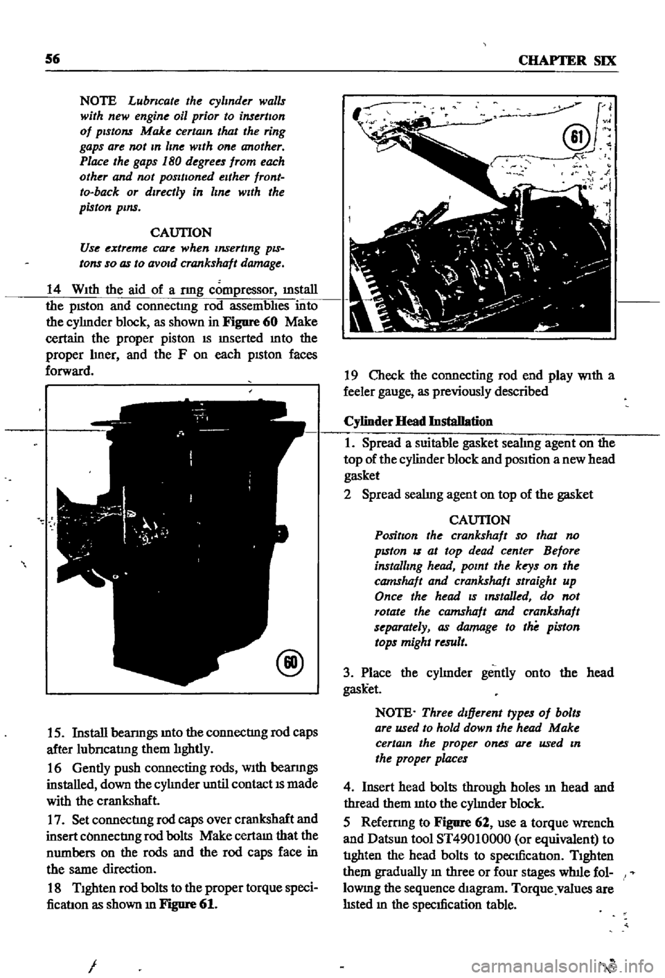
Figure
60
Make
certain
the
proper
piston
IS
mserted
mto
the
proper
hner
and
the
F
on
each
pISton
faces
forward
@
15
Install
beanngs
mto
the
connectIng
rod
caps
after
lubncatmg
them
hghtly
16
Gently
push
connecting
rods
With
beanngs
installed
down
the
cyhnder
until
contact
IS
made
with
the
crankshaft
17
Set
connectIng
rod
caps
over
crankshaft
and
insert
COnnectIng
rod
bolts
Make
certam
that
the
numbers
on
the
rods
and
the
rod
caps
face
in
the
same
direction
18
Tighten
rod
bolts
to
the
proper
torque
speci
ficatIon
as
shown
m
Figure
61
I
J
@v
N
i
19
Check
the
connecting
rod
end
play
With
a
feeler
gauge
as
previously
described
Cylinder
Head
Installation
1
Spread
a
suitable
gasket
seahng
agent
on
the
top
of
the
cylinder
block
and
position
a
new
head
gasket
2
Spread
seahng
agent
on
top
of
the
gasket
CAUTION
PositIon
the
crankshaft
so
that
no
pzston
IS
at
top
dead
center
Before
installing
head
point
the
keys
on
the
camshaft
and
crankshaft
straight
up
Once
the
head
zs
Installed
do
not
rotate
the
camshaft
and
crankshaft
separately
as
damage
to
the
piston
tops
might
result
3
Place
the
cyhnder
gently
onto
the
head
gask
et
NOTE
Three
dIfferent
types
of
bolts
are
used
to
hold
down
the
head
Make
certain
the
proper
ones
are
used
In
the
proper
places
4
Insert
head
bolts
through
holes
ill
head
and
thread
them
mto
the
cyhnder
block
5
Refemng
to
Figure
62
use
a
torque
wrench
and
Datsun
tool
ST49010000
or
equivalent
to
tIghten
the
head
bolts
to
specIficatIon
Tighten
them
gradually
m
three
or
four
stages
wlnle
fol
lOWIng
the
sequence
diagram
Torque
values
are
hsted
m
the
specIfication
table