1968 DATSUN 510 tire pressure
[x] Cancel search: tire pressurePage 11 of 252

CHAPTER
TWO
PERIODIC
MAINTENANCE
To
ensure
good
performance
dependability
and
safety
regular
penodlc
maintenance
is
necessary
TIns
chapter
outlInes
routine
and
penodlc
mamtenance
for
the
average
dnver
Under
heavy
usage
semcmg
mtervals
will
be
shortened
Regular
routme
mamtenance
will
help
aVOId
expensive
repaIrs
ROUTINE
CHECKS
The
followlDg
checks
should
be
performed
at
each
fuel
stop
1
Check
engme
oil
level
Top
up
as
requrred
2
Check
radiator
coolant
level
Top
up
as
re
qwred
3
Check
battery
electrolyte
The
battery
case
IS
marked
With
upper
hrmt
and
lower
lnmt
lInes
Level
should
be
maID
tamed
between
the
IIDes
4
Check
that
the
master
cylInder
brake
flwd
reservOir
level
IS
between
the
max
and
mm
lInes
marked
on
the
plastic
case
S
Check
the
plastic
clutch
cyhnder
reservoir
level
Level
should
be
between
the
max
and
mm
lInes
6
Check
the
windsh1eld
washer
flwd
reservoir
Top
up
as
required
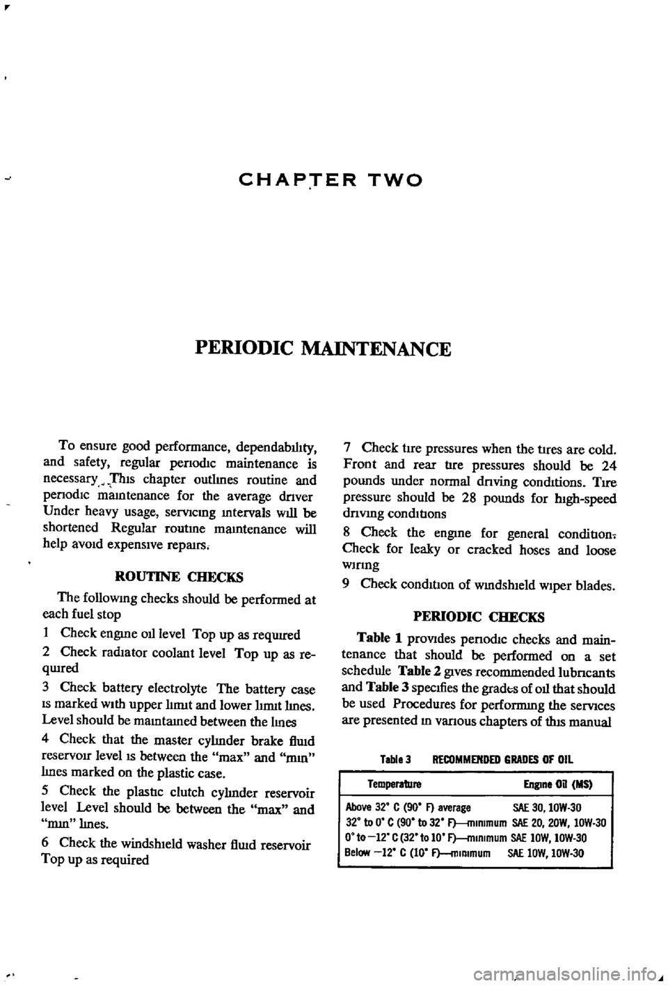
7
Check
tire
pressures
when
the
tIres
are
cold
Front
and
rear
tire
pressures
should
be
24
pounds
under
normal
dnving
conditions
TIre
pressure
should
be
28
pounds
for
h1gh
speed
dnvmg
conditions
8
Check
the
engIne
for
general
conditIon
Check
for
leaky
or
cracked
hoses
and
loose
wmng
9
Check
condition
of
wmdshleld
wiper
blades
PERIODIC
CHECKS
Table
1
prOVIdes
penodIc
checks
and
main
tenance
that
should
be
performed
on
a
set
schedule
Table
2
gIves
recommended
lubncants
and
Table
3
specIfies
the
grades
of
oil
that
should
be
used
Procedures
for
performmg
the
semces
are
presented
ID
vanous
chapters
of
tlus
manual
Table
3
RECOMMENDED
GRADES
OF
OIL
Temperature
Engine
on
MS
Above
32
C
90
F
average
SAE
30
IOW
30
32
to
0
C
90
to
32
F
mlmmum
SAE
20
20W
IOW
30
O
to
12
C
32
tolO
F
mlRlmum
SAE
IOW
IOW
30
Below
12
C
10
F
mlmmum
SAE
lOW
IOW
30
Page 21 of 252

16
CHAPTER
TIlREE
sary
Also
check
all
parts
for
mlSaltgnment
and
uneven
wear
TRANSMISSION
1
Difficult
to
mesh
gears
Make
certam
the
clutch
pressure
plate
and
re
lease
beanng
are
m
good
condItion
The
trouble
can
be
caused
by
worn
gears
shaft
and
or
bear
mgs
DISassemble
and
repaIr
as
requIred
Also
can
be
caused
by
msufficlent
operatmg
stroke
due
to
worn
or
loose
sltdmg
parts
or
a
defective
synchronIZer
DIsassemble
carefully
InSpect
and
replace
as
requIred
2
Gears
slip
out
of
mesh
Generally
thIS
trouble
occurs
when
the
mterlock
plunger
check
ball
and
or
spnng
IS
weakened
or
worn
The
trouble
can
also
be
caused
by
worn
fork
rod
ball
groove
damaged
bearings
or
dam
aged
gears
DIsassemble
carefully
mspect
and
replace
as
required
3
NOIse
If
nOISes
are
heard
wIth
the
engme
idlmg
and
the
clutch
disengaged
the
nOIse
IS
probably
conung
from
the
transmISSIOn
Several
Items
can
cause
nOISes
either
smgly
or
m
combmatIon
Check
the
qualIty
and
quantity
of
lubrIcant
in
the
trans
mISSIon
Replace
or
replenISh
as
necessary
Worn
bearIngs
wIll
usually
produce
a
lugh
humming
at
hIgh
speed
and
a
cycltc
knockIng
sound
at
low
speed
Worn
or
damaged
splInes
and
bushmgs
will
also
cause
nOIse
BRAKES
1
Brake
pedal
goes
to
floor
There
are
numerous
causes
for
thIS
includIng
excessIvely
worn
Itnmgs
aIr
in
the
hydraultc
sys
tem
leaky
brake
lmes
leaky
wheel
cylmders
or
leaky
or
worn
master
cylmder
Check
for
leaks
and
thIn
brake
linmgs
Bleed
and
adjust
the
brakes
If
thIS
doesn
t
cure
the
trouble
rebwld
wheel
cylmders
a
nd
or
master
cylmder
2
Spongy
pedal
Normally
caused
by
aIr
m
the
system
blee
d
and
adjust
the
brakes
3
Brakes
pull
Check
brake
adjustment
Also
check
for
contam
inated
brake
Itmngs
from
leaks
leaky
wheel
cyltnders
loose
caltpers
frozen
or
seIZed
pIstons
and
restrIcted
brake
lmes
or
hoses
In
addItion
check
front
end
alignment
and
suspensIOn
dam
age
such
as
broken
front
or
rear
sprmgs
shocks
etc
Check
condItIon
of
tIres
4
Brakes
squeal
or
chatter
Check
brake
lmmg
thickness
and
brake
drum
roundness
Ensure
that
the
shoes
have
cham
ferred
ends
and
are
not
loose
Inspect
the
condI
tion
of
the
rotors
on
the
front
wheel
dISC
brakes
to
make
certain
they
are
not
scored
or
damaged
Clean
away
all
dIrt
on
shoes
pads
rotors
or
drums
5
Draggmg
brakes
Check
brake
adjustment
includmg
handbrake
Check
for
broken
or
weak
shoe
return
springs
swollen
rubber
parts
due
to
unproper
brake
flUId
or
other
contammatIon
Clean
or
replace
de
fectIve
parts
6
Hard
pedal
Check
brake
linmgs
for
contammation
Also
check
for
restrIcted
brake
lines
and
hoses
7
High
speed
fade
Check
for
dIstorted
or
out
of
round
drums
and
contamInated
brake
lmmgs
Make
certam
the
recommended
brake
flUId
IS
used
Dram
entIre
system
and
refill
If
In
doubt
8
Pulsatmg
pedal
Check
for
dIStorted
or
out
of
round
drums
or
rotors
Check
for
excessIVe
brake
dISC
run
out
STEERING
AND
SUSPENSION
NOTE
Unusual
steermg
pullmg
or
wandermg
IS
usually
caused
by
bent
or
otherwise
mIsaligned
suspenszon
parts
Because
of
the
speCialized
equIp
ment
reqUired
to
evaluate
and
correct
these
faults
It
IS
recommended
t
tat
servIce
to
the
steermg
and
suspension
system
be
referred
to
your
Datsun
dealer
oca
quallfied
specrallst
m
thiS
field
1
VibratIOn
felt
m
steermg
wheel
VIbratIon
can
be
caused
by
several
thmgs
includ
ing
lll1proper
aIr
pressure
m
tIres
uneven
wear
Page 22 of 252

TROUBLESHOOTING
17
of
tIre
loose
wheels
unproper
adjustment
or
wear
of
front
wheel
bearIngs
faulty
wheel
align
ment
or
wear
of
transverse
lInk
and
tension
rod
bushings
Inspect
all
parts
carefully
for
wear
or
damage
Replace
or
replUI
parts
as
required
2
Shock
transmltled
through
steering
wheel
This
is
usually
most
noticeable
when
traveling
over
bad
roads
at
relatively
high
speeds
Causes
Include
damage
to
the
idler
ann
insuffiCient
tIghtening
of
steenng
gear
box
wear
of
the
steer
Ing
linkage
and
wear
of
the
suspension
ball
joint
Inspect
all
parts
for
wear
or
damage
Refer
to
Chapter
ThIrteen
for
service
or
repair
you
can
perform
and
for
procedures
which
should
be
referred
to
your
deal
r
3
Shlmmymg
This
is
usually
most
noticeable
when
a
specIfic
speed
IS
attained
and
will
normally
repeat
at
that
speed
Causes
are
generally
unbalanced
wheels
unproper
adjustment
of
steenng
gear
insuffi
cient
backlash
malfunction
of
the
shock
ab
sorbers
or
loose
bolts
for
the
strut
mountIng
Reparr
or
replace
defective
parts
as
required
Refer
to
Chapter
Thirteen
4
Wandermg
of
car
m
one
dlrectlOnl
This
problem
can
be
caused
by
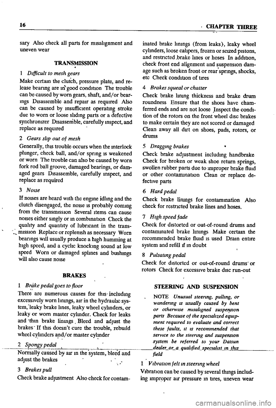
improper
air
pressure
loose
wheel
nuts
difference
in
tire
tread
wear
from
left
to
right
side
Incorrect
adjustment
of
wheel
bearings
defectIve
wheel
beanngs
collapsing
or
twistIng
of
front
spnng
or
Incorrect
wheel
alignment
Also
binding
of
the
brake
shoes
worn
bushings
in
the
transverse
link
or
the
tension
rod
and
deformation
of
s
enng
lInkage
and
suspension
link
can
cause
wander
Carefully
iuspect
all
parts
for
looseness
and
wear
and
re
place
or
repaIr
as
required
In
some
c
ases
a
de
fective
rear
suspension
may
also
cause
the
vehicle
to
wander
5
InstabIlity
Instability
can
be
caused
by
unproper
tIre
pres
sures
worn
bushings
in
the
transverse
link
and
tension
rod
mcorrect
wheel
alignment
worn
steenng
linkage
Incorrect
adjustment
of
steer
ing
gear
and
unbalanced
wheels
Inspect
all
parts
carefully
for
wear
and
damage
Adjust
repair
or
replace
as
required
6
Heavy
feelmg
m
steering
This
can
be
caused
by
improper
tIre
pressures
insuffiCient
or
contamInated
lubncant
in
gear
box
damage
or
insuffiCient
grease
In
suspeuslon
ball
Joint
damaged
or
badly
adjusted
wheel
bearIngs
worn
or
damaged
steermg
gear
dam
age
of
upper
strut
bearing
and
mterference
of
steenng
column
With
turn
signal
SWitch
Inspect
all
parts
carefully
for
wear
and
damage
Adjust
repair
or
replace
as
required
7
ExceSSIve
play
m
steermg
wheel
This
is
usually
caused
by
Incorrect
adjustment
of
the
steenng
gear
worn
bushings
in
the
steering
linkage
or
Idler
arm
mcorrect
adjustment
of
the
front
wheel
bearings
worn
bushIngs
in
the
trans
verse
lInk
and
tension
rod
Carefully
inspect
all
parts
for
wear
or
damage
Adjust
repair
or
re
place
as
reqUIred
TIRE
WEAR
ANALYSIS
Abnormal
tIre
wear
should
always
be
ana
lyzed
to
deternune
the
cause
The
most
common
are
Incorrect
tIre
pressure
improper
dnving
overloading
and
Incorrect
wheel
ahgDment
Figures
2A
through
2F
identify
wear
patterns
and
mdicate
likely
causes
Of
I
1
l
D
1
Undennflatlon
Worn
more
on
Sides
than
In
center
Page 90 of 252

COOLING
SYSTEM
8S
and
In
those
with
exhaust
and
evaporatIve
emIS
sion
control
devIces
a
fan
clutch
IS
combIned
WIth
the
thermostat
to
detect
temperature
m
the
engme
compartlnent
When
the
temperature
nses
the
thermostat
detects
the
change
an
the
fan
clutch
engages
thereby
helpmg
to
cool
the
engme
WATER
PUMP
Figure
2
page
86
IS
an
exploded
drawmg
of
the
water
pump
and
fan
assembly
for
1970
to
1971
The
top
half
of
the
IllustratIon
applIes
to
those
models
WIth
exhaust
and
evaporatIve
emiSSIOn
control
systems
The
bottom
half
covers
models
WIth
a
crankcase
emiSSIon
control
deVIce
only
Figure
3
page
87
IS
an
exploded
drawmg
of
the
water
pump
and
fan
assembly
for
1968
models
Without
exhaust
or
evaporatIve
controls
Figure
4
page
88
shows
the
1968
model
With
emISSIon
control
deVIce
As
can
be
seen
from
the
illustratIons
most
dIfferences
eXISt
withIn
the
fan
clutch
assembly
Water
Pump
Removal
1
Remove
upper
and
lower
radIator
hoses
from
the
thermostat
housmg
and
cylmder
block
re
spectIvely
Dram
coolant
from
rad1ator
and
cylInder
block
2
Loosen
the
alternator
mountlng
bolt
and
the
adjustIng
bolt
on
the
alternator
mountIng
bracket
3
Move
the
alternator
toward
the
cylinder
block
untIl
slack
IS
eVIdent
10
the
fan
belt
Re
move
fa
belt
fro
alternator
water
pump
and
crankshaft
pulley
4
It
IS
difficult
to
remove
the
water
pump
from
the
front
housmg
With
the
radiator
and
top
shroud
10
place
so
remove
them
5
Remove
the
bolts
holdmg
the
fan
assembly
to
the
water
pump
and
remove
the
fan
assembly
6
Remove
the
bolts
holdmg
the
water
pump
to
the
front
housmg
as
shown
In
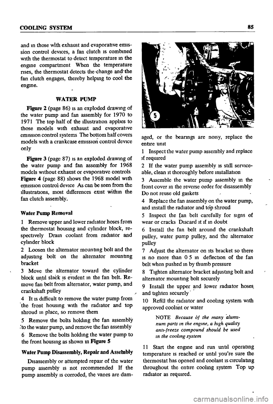
Figure
S
Water
Pump
Disassembly
Repair
and
Assembly
Disassembly
or
attempted
repaIr
of
the
water
pump
assembly
IS
not
recommended
If
the
pump
assembly
IS
corroded
the
vanes
are
dam
aged
or
the
bearmgs
are
nOISY
replace
the
entIre
umt
1
Inspect
the
water
pump
assembly
and
replace
If
reqUIred
2
If
the
water
pump
assembly
IS
stIll
serVIce
able
clean
It
thoroughly
before
mstallatIon
3
Assemble
the
water
pump
assembly
m
the
front
cover
10
the
reverse
order
for
disassembly
Do
not
reuse
old
gaskets
4
Replace
the
fan
assembly
on
the
water
pump
and
mstall
the
radiator
and
top
shroud
5
Inspect
the
fan
belt
carefully
for
SIgnS
of
wear
or
cracks
DIscard
It
If
10
doubt
6
Install
the
fan
belt
around
the
crankshaft
pulley
water
pump
pulley
and
the
alternator
pulley
7
Adjust
the
alternator
on
Its
bracket
so
there
IS
no
more
than
0
5
10
deflection
of
the
fan
belt
when
pushed
10
by
thumb
pressure
8
TIghten
alternator
bracket
adjustIng
bolt
and
alternator
mountmg
bolt
securely
9
Install
the
upper
and
lower
rad1ator
hoses
and
tIghten
securely
10
Refill
the
radIator
and
coolmg
system
With
approved
coolant
or
water
NOTE
Because
of
the
many
aluml
num
parts
In
the
engine
a
hIgh
qualIty
antI
freeze
compound
should
be
used
In
the
cooling
system
11
Start
the
engme
and
run
untIl
operatIng
temperature
IS
reached
or
untIl
you
re
sure
the
thermostat
has
opened
and
coolant
IS
CIrCulatIng
throughout
the
entIre
coolIng
system
Top
up
radIator
as
reqUIred
Page 94 of 252

COOLING
SYSTEM
89
FAN
CLUTCH
Fan
Clutch
Operation
and
Inspection
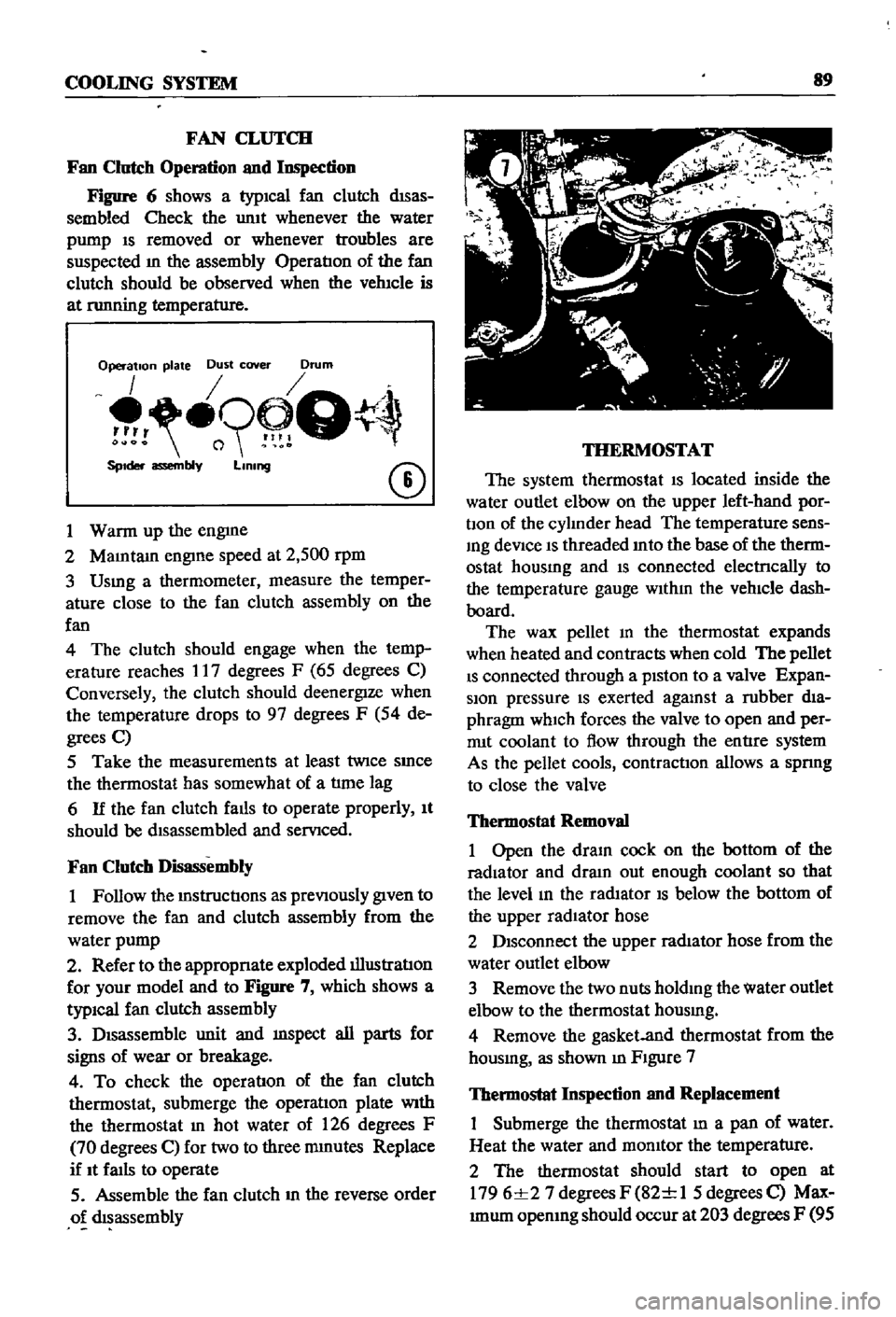
Figure
6
shows
a
typICal
fan
clutch
dISas
sembled
Check
the
umt
whenever
the
water
pump
IS
removed
or
whenever
troubles
are
suspected
m
the
assembly
OperatIon
of
the
fan
clutch
should
be
observed
when
the
vehIcle
is
at
nmning
temperature
Operation
plate
Dust
cover
Drum
o9
Q
SpIder
assembly
LIning
CD
1
Warm
up
the
engme
2
MaIntam
engIne
speed
at
2
500
rpm
3
Usmg
a
thermometer
measure
the
temper
ature
close
to
the
fan
clutch
assembly
on
the
fan
4
The
clutch
should
engage
when
the
temp
erature
reaches
17
degrees
F
65
degrees
C
Conversely
the
clutch
should
deenergIze
when
the
temperature
drops
to
97
degrees
F
54
de
grees
C
5
Take
the
measurements
at
least
twice
SInce
the
thermostat
has
somewhat
of
a
tlme
lag
6
If
the
fan
clutch
falls
to
operate
properly
It
should
be
dIsassembled
and
servIced
Fan
Clutch
Disassembly
1
Follow
the
mstructIons
as
prevIOusly
gIven
to
remove
the
fan
and
clutch
assembly
from
the
water
pump
2
Refer
to
the
appropnate
exploded
illustratIon
for
your
model
and
to
Figure
7
which
shows
a
typiCal
fan
clutch
assembly
3
DIsassemble
unit
and
mspect
all
parts
for
signs
of
wear
or
breakage
4
To
check
the
operatIon
of
the
fan
clutch
thermostat
submerge
the
operatIon
plate
With
the
thermostat
In
hot
water
of
126
degrees
F
70
degrees
C
for
two
to
three
mmutes
Replace
if
It
faIls
to
operate
5
Assemble
the
fan
clutch
m
the
reverse
order
o
dIsassembly
THERMOSTAT
The
system
thermostat
IS
located
inside
the
water
outlet
elbow
on
the
upper
left
hand
por
bon
of
the
cylInder
head
The
temperature
sens
Ing
deVice
IS
threaded
Into
the
base
of
the
therm
ostat
housmg
and
IS
connected
electrlcally
to
the
temperature
gauge
WIthIn
the
vehIcle
dash
board
The
wax
pellet
m
the
thermostat
expands
when
heated
and
contracts
when
cold
The
pellet
IS
connected
through
a
pIston
to
a
valve
Expan
sion
pressure
IS
exerted
agalUst
a
rubber
dIa
phragm
which
forces
the
valve
to
open
and
per
rrut
coolant
to
flow
through
the
entIre
system
As
the
pellet
cools
contractIOn
allows
a
spnng
to
close
the
valve
Thermostat
Removal
1
Open
the
draIn
cock
on
the
bottom
of
the
radiator
and
dram
out
enough
coolant
so
that
the
level
In
the
radIator
IS
below
the
bottom
of
the
upper
radIator
hose
2
DIsconnect
the
upper
radIator
hose
from
the
water
outlet
elbow
3
Remove
the
two
nuts
holdIng
the
water
outlet
elbow
to
the
thermostat
housmg
4
Remove
the
gasket
and
thermostat
from
the
housmg
as
shown
m
FIgure
7
Thermostat
Inspection
and
Replacement
Submerge
the
thermostat
In
a
pan
of
water
Heat
the
water
and
momtor
the
temperature
2
The
thermostat
should
start
to
open
at
1796
1
27
degrees
F
82
1
1
5
degrees
C
Max
Imum
opemng
should
occur
at
203
degrees
F
95