1968 DATSUN 510 fuel filter
[x] Cancel search: fuel filterPage 9 of 252
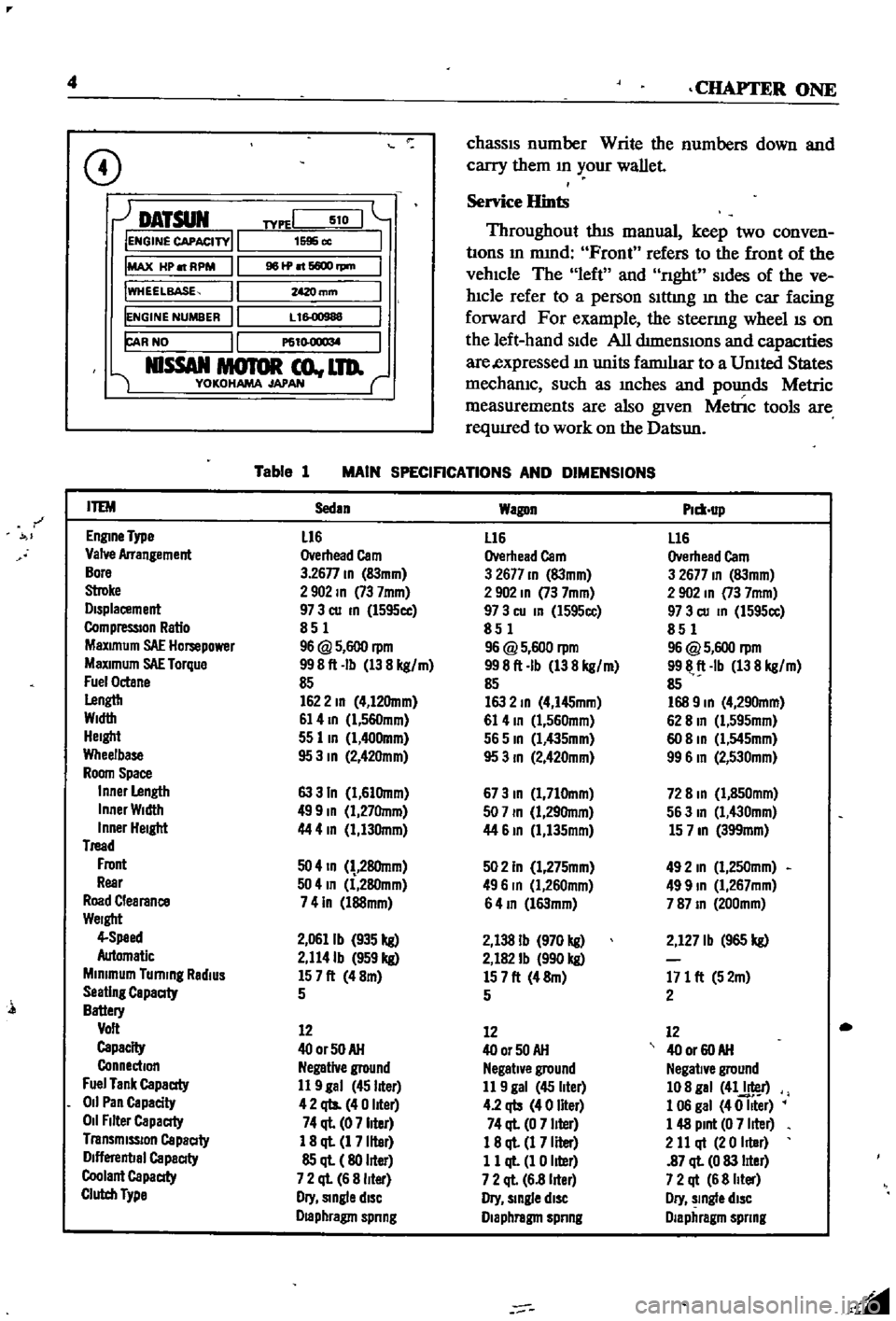
4
CHAPTER
ONE
chassIs
number
Write
the
numbers
down
and
carry
them
ill
your
wallet
Service
Hints
Throughout
thIs
manual
keep
two
conven
bons
ill
mmd
Front
refers
to
the
front
of
the
vehicle
The
left
and
nght
sides
of
the
ve
hicle
refer
to
a
person
sittIng
ill
the
car
facing
forward
For
example
the
steenng
wheelIS
on
the
left
hand
Side
All
dimensIOns
and
capacities
are
expressed
ill
units
fanuhar
to
a
Umted
States
mechaniC
such
as
illches
and
pounds
Metric
measurements
are
also
given
Metnc
tools
are
reqUITed
to
work
on
the
Datsun
CD
DATSUN
IENGINE
CAPACITY
IMAX
HP
RPM
IWHEELBASE
IENGINE
NUMBER
FAR
NO
NlSSAN
MOTOR
co
LTD
YOKOHAMA
JAPAN
TYPEI
510
1595
cc
961P
6600
rpm
mm
L
1
00988
P61
l
O
1
l
M
Table
1
MAIN
SPECIFICATIONS
AND
DIMENSIONS
r
ITEM
Sedan
Wagon
Plm
up
EnglDe
Type
L16
L16
L16
Valve
Arrangement
Overhead
Cam
Overhead
Cam
Overhead
Cam
Bore
3
26n
ID
83mm
3
2677
ID
83mm
3
2677
ID
83mm
Stroke
2902
ID
73
7mm
2
902
ID
73
7mm
2
902
In
73
7mm
Displacement
97
3
cu
ID
l595cc
97
3
cu
In
l595cc
97
3
cu
ID
1595cc
CompressIOn
Ratio
851
851
851
MaXimum
SAE
Hompower
96
@
5
600
rpm
96
@
5
600
rpm
96
@
5
600
rpm
MaXimum
SAE
Torque
998ft
Ib
138
kg
m
998ft
Ib
138
kg
m
9911
ft
Ib
138
kg
m
Fuel
Octane
85
85
85
Lengtb
1622
ID
4
12Omm
163
2
ID
4
I45mm
168
9
ID
4
290mm
Width
61
4
ID
l
560mm
61
4
ID
1
560mm
62
8
In
Cl
595mm
Height
55
lID
1
400mm
565
ID
Cl
435mm
60
8
ID
Cl
545mm
Wheelbase
95
3
ID
2
42Omm
95
3
ID
2
420mm
99
6
In
2
530mm
Room
Space
Inner
Length
63
3
In
1
61Omm
673
ID
1
710mm
72
8
ID
1
850mm
Inner
Width
499
ID
1
27Omm
507
ID
1
29Omm
563
In
1
430mm
Inner
Height
44
4
In
1
130mm
44
61D
1
135mm
15
7
ID
399mm
Tread
Front
50
4
ID
28Omm
502
In
1
275mm
492
In
1
250mm
Rear
504
In
1
280mm
496
In
Cl
260mm
499
ID
1
267mm
Road
Clearance
741n
l88mm
64
ID
l63mm
787
ID
200mm
Weight
4
Speed
2
0611b
935
kg
2
138
Ib
970
kg
2
127
Ib
965
kg
Automatic
2
114Ib
959
kg
2
182
Ib
990
kg
Minimum
Turning
RadiUS
157ft
48m
157ft
48m
171
ft
52m
Seating
Capaaty
5
5
2
Battery
Volt
12
12
12
Capacity
400rSOAH
400r50AH
40
or
60
AH
Connection
Negative
ground
Negative
ground
Negative
ground
Fuel
Tank
Capaaty
11
9
gal
45
liter
11
9
gal
45
liter
108
gal
41J
r
011
Pan
Capacity
42
qts
40
liter
4
2
qb
40
liter
1
06
gal
40
Iller
011
Filter
Capaaty
74
ql
07
liter
74
ql
0
7
liter
1
48
Pint
0
7
liter
Transmission
Capaaty
1
8
ql
1
7
liter
18
ql
1
7
Iller
2
11
qt
20
Iller
Dlflerenbal
Capaaty
85
ql
80
liter
11
ql
1
0
liter
87
ql
0
83
lIter
Coolant
Capaaty
7
2
ql
6
8
liter
7
2
ql
6
8
lIter
7
2
qt
6
8
Iller
Clutch
Type
Dry
Single
diSC
Dry
slDgle
diSC
Dry
slDgle
diSC
Draphragm
spnng
Diaphragm
spnng
Diaphragm
spnng
l
Page 12 of 252

PERIODIC
MAINTENANCE
7
Table
1
ENGINE
LUBRICATION
AND
MAINTENANCE
FREQUENCY
EVERY
E
E
E
E
E
E
E
Eo
00
00
00
00
00
00
00
gq
00
00
00
NO
t
r61li
0
CD
Check
engine
011
level
top
up
If
required
X
Change
engine
011
X
Lubricate
carburetor
hnkage
X
Lubricate
distributor
rotor
shaft
and
ann
shaft
X
Apply
grease
to
distributor
cam
heel
X
Check
radiator
coolant
level
X
Change
radIator
coolant
X
Change
radiator
coolant
additive
X
Check
battery
electrolyte
level
X
Check
specific
gravity
of
battery
X
Check
engine
starting
exhaust
color
X
Tighten
cyhnder
head
manifolds
and
pipe
flanges
X
Adjust
valve
clearance
X
Check
Ignition
timing
X
Tighten
carburetor
fittings
X
Check
fan
belt
tension
X
Check
for
011
pan
leakage
X
Tighten
engine
mounts
X
Check
fuel
strainer
X
Replace
fuel
strainer
X
Check
for
fuel
leaks
X
Replace
011
filter
X
Check
spark
plugs
X
Replace
spark
plugs
X
Check
dlstnbutor
cap
rotor
and
POints
X
Adjust
engine
Idle
speed
X
Check
air
cleaner
fittings
X
Clean
011
filler
cap
X
Clean
battery
cables
and
terminals
X
Check
alternator
and
voltage
regulator
function
X
Check
starter
motor
function
X
Replace
aIr
cleaner
element
X
Check
fuel
pump
function
X
Check
cyhnder
compressIon
X
Clean
carburetor
Jets
and
float
chamber
X
Check
dlstnbutor
condenser
X
Check
crankcase
ventilation
control
valve
X
Page 18 of 252

TROUBLESHOOTING
13
trouble
may
also
be
worn
bearings
Remove
the
alternator
and
repair
ENGINE
These
procedures
assume
the
starter
cranks
the
engme
over
normally
If
not
refer
to
Starter
section
m
this
chapter
1
Engme
won
t
start
Could
be
caused
by
the
IgOltlon
or
fuel
problems
First
determine
If
high
voltage
to
spark
plug
occurs
To
do
thiS
dISconnect
one
of
the
spark
plug
wires
Hold
the
exposed
wrre
termlOal
y
to
Y2
lOch
from
ground
any
metal
in
engine
com
partment
With
an
msulated
screwdriver
Crank
the
engme
over
If
sparks
do
not
Jump
to
ground
or
the
sparks
are
very
weak
the
trouble
may
be
10
the
IgnitIOn
system
See
Ignition
System
Trou
bleshootmg
to
further
check
If
sparks
occur
properly
the
trouble
may
be
10
the
fuel
system
See
Fuel
System
Troubleshootmg
2
Engme
misses
steadily
Remove
one
spark
plug
wrre
at
a
tune
and
ground
the
wrre
If
engme
mISs
increases
that
cyhnder
was
work
109
properly
Reconnect
the
wire
and
check
the
others
When
a
wire
IS
dIs
connected
and
engme
miss
remams
the
same
that
cylinder
IS
not
finng
Check
spark
as
descnbed
10
Step
1
If
no
spark
occurs
for
one
cyhnder
only
check
dlStnbutor
cap
wrre
and
spark
plug
If
spark
occurs
prop
erly
check
compressIOn
and
mtake
maOlfold
vacuum
to
ISolate
the
trouble
3
Engme
misses
erratlcally
at
all
speeds
Interrmttent
trouble
can
be
difficult
to
find
It
could
be
ill
the
Ignition
system
exhaust
system
or
fuel
system
Follow
troubleshooting
proce
dures
for
these
systems
carefully
to
isolate
the
trouble
4
Engme
misses
at
Idle
only
Trouble
could
exist
anywhere
ill
IgOltlon
system
Follow
Ignition
TroubleshootlOg
procedure
care
fully
Trouble
could
also
eXist
10
the
carburetor
Idle
crrcult
Check
Idle
mIXture
adjustment
and
check
for
restnctions
m
the
idle
crrcUlt
5
Engme
misses
at
high
speed
only
Problems
could
be
ill
the
fuel
or
IgOltlon
systems
heck
accelerator
pump
operation
fuel
pump
dehvery
fuel
hnes
etc
as
descnbed
under
Fuel
System
Troubleshootillg
Also
check
spark
plugs
and
wrres
6
Low
performance
at
all
speeds
poor
acceleratIOn
Trouble
usually
ill
IgOltlon
or
fuel
system
Check
each
With
the
appropnate
troubleshooting
pro
cedure
7
ExceSSive
fuel
consumptIOn
Could
be
caused
by
a
Wide
variety
of
seemmgly
unrelated
factors
Check
for
clutch
shppage
brake
drag
defective
wheel
beanngs
or
poor
front
end
alignment
Check
IgOltlOn
system
and
fuel
system
8
011
pressure
lamp
does
not
light
when
IgmtlOn
switch
IS
on
Check
the
alternator
warning
lamp
If
it
ISn
t
on
either
go
to
Step
1
Chargmg
System
Trouble
shootlOg
If
only
the
oil
pressure
lamp
IS
off
open
the
englOe
compartment
hd
and
locate
the
oil
pressure
sender
on
the
block
near
the
oil
filter
Make
sure
the
wrre
is
connected
to
the
sender
and
makmg
good
contact
Pull
the
wrre
off
and
ground
it
If
the
lamp
hghts
replace
the
sender
If
the
lamp
does
not
light
replace
the
lamp
9
011
pressure
lamp
lights
or
flickers
when
engme
IS
runmng
Indicates
low
or
complete
loss
of
oil
pressure
Stop
the
englOe
unmedmtely
coast
to
a
stop
With
the
clutch
dISengaged
Tlus
may
simply
be
caused
by
a
low
oil
level
or
an
overheatmg
en
glOe
Check
the
oil
level
and
fan
belt
tensIOn
Check
for
a
shorted
oil
pressure
sender
with
an
ohmmeter
or
a
contlOulty
tester
Remove
and
clean
the
oil
dipstick
and
check
oil
level
and
condition
RepleOlsh
or
replace
the
oil
as
re
qurred
Listen
for
unusual
nOISes
mdlcatmg
dam
aged
beanngs
etc
Do
not
re
start
the
engine
until
you
know
why
the
hght
went
on
and
are
sure
that
the
problem
has
been
corrected
IGNITION
SYSTEM
This
procedure
assumes
the
battery
IS
ill
good
enough
condition
to
crank
the
engme
at
a
normal
rate
Page 27 of 252
22
CHAPTER
FOUR
CD
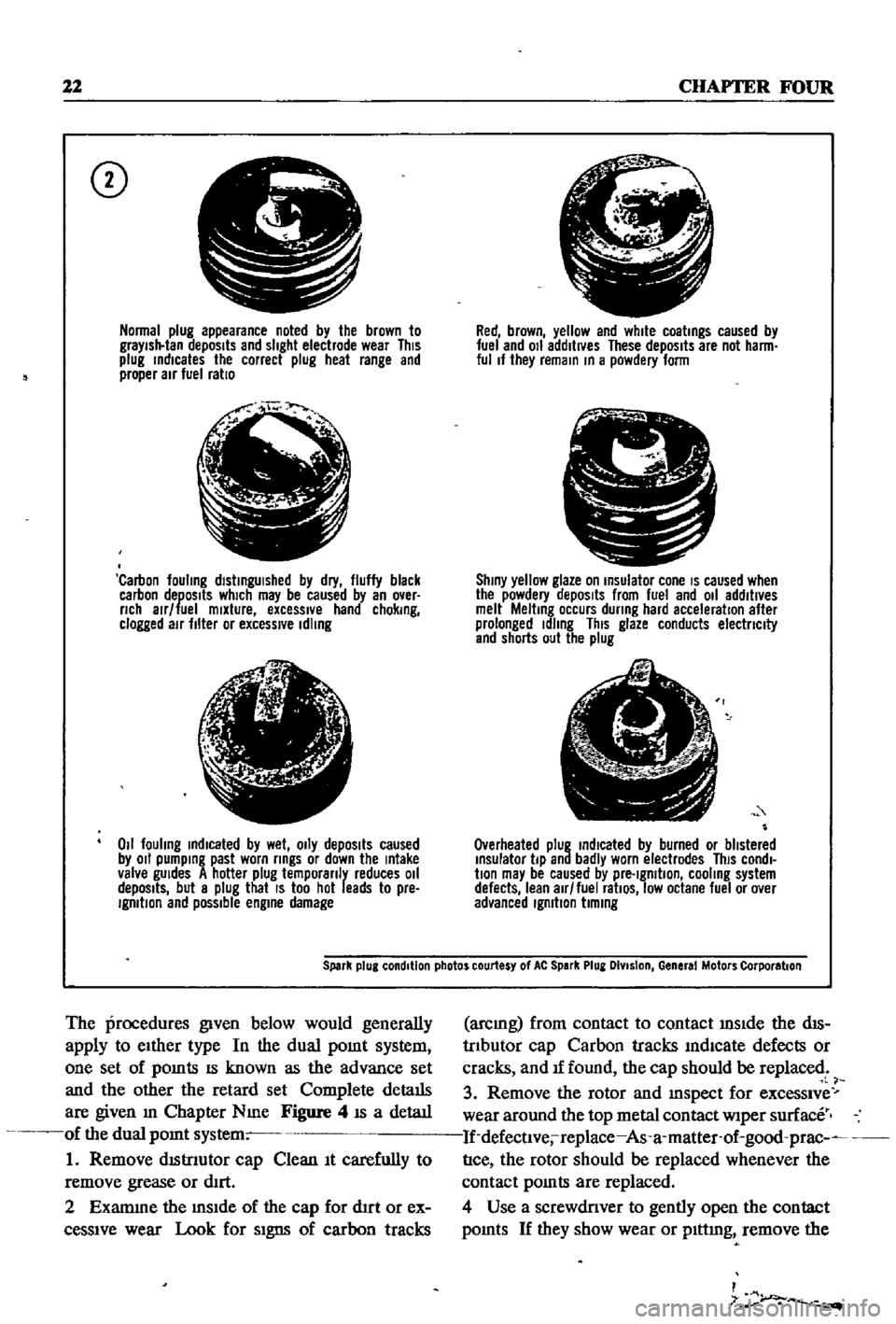
Normal
plug
appearance
noted
by
the
brown
to
graYish
tan
deposits
and
slight
electrode
wear
This
plug
rndlcates
the
correct
plug
heat
range
and
proper
air
fuel
ratio
f
j
l
Carbon
fouling
dlstrngUlshed
by
dry
fluffy
black
carbon
deposits
which
may
be
caused
by
an
over
nch
alr
fuel
mixture
excessIVe
hand
chokrng
clogged
air
filter
or
excessive
Idling
lJ
6
1
4i
Z
011
fouling
rndlcated
by
wet
OIly
depOSits
caused
by
011
pumprng
past
worn
rrngs
or
down
the
rntake
valve
gUides
A
hotter
plug
temporanly
reduces
011
depOSits
but
a
plug
that
IS
too
hot
leads
to
pre
IgmtlOn
and
possible
engrne
damage
Red
brown
yellow
and
white
coatrngs
caused
by
fuel
and
011
additives
These
depOSits
are
not
harm
ful
If
they
remarn
rn
a
powdery
form
C
I
Shrny
yellow
glaze
on
rnsulator
cone
IS
caused
when
the
powdery
depOSits
from
fuel
and
011
additives
melt
Meltrng
occurs
dunng
hard
acceleration
after
prolonged
Idling
This
glaze
conducts
electnclty
and
shorts
out
the
plug
Overheated
plug
rndlcated
by
burned
or
blistered
rnsulator
tip
and
badly
worn
electrodes
This
condl
bon
may
be
caused
by
pre
Igmtlon
cooling
system
defects
lean
air
fuel
ratiOS
low
octane
fuel
or
over
advanced
Igmbon
bmrng
Spark
plug
condition
photos
courtesy
of
At
Spark
Plug
DIvision
General
Motors
Corporation
The
procedures
given
below
would
generally
apply
to
eIther
type
In
the
dual
pomt
system
one
set
of
pomts
IS
known
as
the
advance
set
and
the
other
the
retard
set
Complete
details
are
given
m
Chapter
Nme
Figure
4
IS
a
detaIl
of
the
dual
pomt
system
1
Remove
dIStnutor
cap
Clean
It
carefully
to
remove
grease
or
dIrt
2
Examme
the
mSIde
of
the
cap
for
d1rt
or
ex
ceSSIve
wear
Look
for
SIgns
of
carbon
tracks
arcmg
from
contact
to
contact
mSIde
the
dIS
trIbutor
cap
Carbon
tracks
mdlcate
defects
or
cracks
and
If
found
the
cap
should
be
replaced
3
Remove
the
rotor
and
mspect
for
exceSSIve
wear
around
the
top
metal
contact
wiper
surface
If
defectlve
replace
As
a
matter
of
good
prac
nce
the
rotor
should
be
replaced
whenever
the
contact
pomts
are
replaced
4
Use
a
screwdriver
to
gently
open
the
contact
pomts
If
they
show
wear
or
plttmg
remove
the
I
7
r
Page 31 of 252
26
CHAPTER
FOUR
2
Check
all
belts
hoses
and
fuellmes
Replace
If
reqUIred
Check
the
tensIon
of
the
belts
for
the
au
pump
and
the
alternator
Adjust
as
re
qUIred
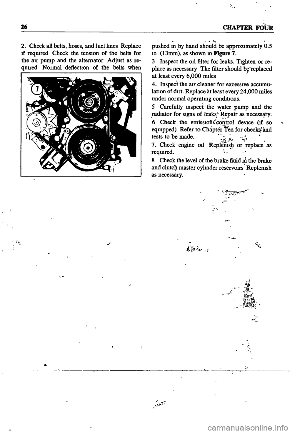
Normal
deflection
of
the
belts
when
pushed
m
by
hand
should
be
approXImately
0
5
m
13mm
as
shown
m
Figure
7
3
Inspect
the
011
filter
for
leaks
TIghten
or
re
place
as
necessary
The
filter
should
replaced
at
least
every
6
000
mIles
4
Inspect
the
lIlr
cleaner
for
excessIve
accumu
latIon
of
dIrt
Replace
at
least
every
24
000
miles
under
normal
operatmg
cornhtIons
5
Carefully
mspect
the
water
pump
and
the
radIator
for
SIgnS
of
leaks
Repair
as
necessl
i
y
6
Check
the
emissIoo
control
deVice
If
so
eqwpped
Refer
to
Chapter
Ten
for
checks
and
tests
to
be
made
c
1
7
Check
engine
oIl
Replems
9
or
replace
as
reqUIred
8
Check
the
level
of
the
brake
fluid
m
the
brake
and
clutcJ1
master
cylmder
reservOirs
ReplenISh
as
necessary
ii
t
d
fl
tlJ
l
Page 64 of 252

ENGINE
59
2
Coat
the
pan
gasket
on
both
sides
With
gasket
compound
and
attach
the
oil
pan
to
the
cyhnder
block
Torque
as
specIfied
Manifold
and
Carburetor
Installation
1
Install
the
mtake
and
exhaust
manIfolds
WIth
associated
gasket
to
the
cylmder
head
2
Mount
the
carburetor
and
gasket
to
the
mtake
manIfold
2
Adjust
all
mtake
and
exhaust
valves
to
the
specIfied
clearance
for
a
cold
engme
Clutch
Assembly
Installation
CAUTION
Take
extreme
care
not
to
get
grease
or
011
on
the
clutch
or
flywheel
frlc
hon
contact
surfaces
1
Place
the
clutch
disc
assembly
on
the
flywheel
With
the
longer
chamfered
splmed
end
of
the
dISC
toward
the
transmISSion
2
Visually
align
or
use
a
dummy
splmed
dnve
shaft
to
ahgn
the
diSC
assembly
With
the
flywheel
pilot
beanng
3
Install
and
tighten
the
SIX
bolts
holdmg
the
clutch
cover
assembly
to
the
flywheel
Tighten
the
bolts
a
turn
each
tune
by
diagonal
pattern
until
they
are
tight
Tlghtenmg
torque
should
be
174
to
188ft
lbs
24
to
2
6
kg
m
NOTE
There
are
two
dowels
on
the
flywheel
to
locate
the
clutch
cover
4
Remove
dummy
shaft
If
used
after
the
above
bolts
are
fully
tightened
5
Refit
the
release
bearing
and
translI11Ssion
case
Miscellaneous
Installation
1
Connect
the
fuel
hose
on
the
front
part
of
the
engme
to
the
fuel
pump
and
to
the
carburetor
2
Gap
the
spark
plugs
and
mstall
them
usmg
new
gaskets
3
Coat
the
rocker
arm
cover
gasket
With
sealer
and
position
It
on
the
cylmder
head
4
Install
the
rocker
arm
cover
and
tighten
the
two
thumb
screws
that
hold
it
m
place
5
Install
distrIbutor
makmg
certam
that
the
notch
on
the
distributor
shaft
assembly
mates
With
the
drive
spmdle
Ahgn
the
location
marks
made
dunng
disassembly
so
that
the
distrIbutor
is
positioned
as
before
6
Install
and
tighten
the
bolts
which
hold
the
dIStributor
to
the
front
cover
7
Install
pomts
condenser
and
rotor
8
Replace
distrIbutor
cap
and
attach
spark
plug
Wires
m
the
correct
sequence
Make
certain
that
all
wires
are
firmly
seated
m
the
distrIbutor
cap
and
attached
securely
to
the
spark
plugs
9
HOISt
the
engme
assembly
from
the
work
stand
10
Install
the
alternator
bracket
alternator
and
engme
mounts
to
the
block
11
Install
the
IgnItIon
coil
oil
filter
oil
pressure
SWitch
dipstick
and
water
drain
plug
12
Connect
the
vacuum
Ime
between
the
dis
trIbutor
and
carburetor
13
Connect
the
transIDlSSlOn
to
the
engine
prior
to
mstallatIon
m
the
vehicle
Engine
Installation
Installation
is
the
reverse
of
the
procedures
followed
m
removal
Be
certaIn
thatlall
battery
connections
are
made
that
water
hoses
are
se
cured
wmng
IS
connected
properly
and
that
all
required
bolts
and
mounts
are
mstalled
and
tightened
Replace
the
radiator
fan
belts
and
radiator
shroud
Fill
the
engme
With
the
proper
grade
of
oil
and
the
radiator
With
recommended
coolant
Install
the
hood
to
the
hInges
according
to
the
marks
made
dUrIng
removal
SERVICE
DATA
AND
SPECIFICATIONS
Table
1
covers
servIce
data
and
engme
Speci
fications
Page 67 of 252
CHAPTER
SEVEN
FUEL
SYSTEM
The
fuel
system
mcludes
the
fuel
tank
straIner
pump
carburetor
arr
cleaner
and
necessary
lines
Inspect
components
for
leaks
and
deterioratIOn
whenever
mamtenance
is
done
The
fuel
stramer
should
be
mspected
peri
odIcally
and
cleaned
AIR
CLEANER
The
au
filter
element
is
viscous
paper
and
does
not
require
cleanmg
Replace
It
every
24
000
mlles
or
more
frequently
under
harsh
condItIons
Several
mInor
differences
exist
between
vehicles
dependmg
on
the
type
of
emisSIOn
con
trol
device
used
Figure
1
shows
location
of
the
air
cleaner
on
the
engme
and
parts
compnsing
the
cleaner
system
on
model
years
through
1969
Figure
2
shows
the
changes
for
1970
and
later
Warm
air
is
supplIed
to
the
air
cleaner
from
the
exhaust
mamfold
to
prevent
carburetor
Icmg
AIR
CLEANER
REMOVAL
AND
REPLACEMENT
1
Unthread
the
WIng
nut
atop
the
cleaner
assembly
2
Remove
the
two
bolts
holdIng
the
air
cleaner
to
the
support
3
Disconnect
the
aIr
cleaner
duct
from
the
base
of
the
cleaner
intake
throat
4
LIft
off
the
aIr
cleaner
body
and
remove
the
aIr
filter
as
shown
m
Figure
3
To
remove
the
arr
cleaner
proceed
as
follows
1
Perform
steps
1
through
4
above
2
Unscrew
the
band
bolt
at
the
base
of
the
air
cleaner
3
DIsconnect
all
hoses
leadmg
to
the
air
cleaner
4
Pull
up
on
the
body
of
the
air
cleaner
and
remove
from
carburetor
5
Except
for
the
au
filter
element
thoroughly
clean
all
parts
6
Reverse
the
steps
above
for
reassembly
FUEL
STRAINER
The
fuel
stramer
IS
located
on
the
nght
hand
side
of
the
engme
compartment
Figure
4
shows
the
fuel
stratner
hoses
clamps
and
the
mount
Ing
clIp
that
holds
the
fuel
stramer
In
place
The
fuel
stramer
IS
of
the
cartrIdge
type
and
uses
a
fiber
mat
and
nylon
as
strainer
elements
The
fuel
stramer
should
be
mspected
frequently
for
foreIgn
material
and
replaced
at
least
every
24
000
rmles
1
DIsconnect
the
inlet
and
outlet
hoses
from
the
fuel
stratner
Make
certatn
that
the
mlet
hose
bottom
IS
not
permItted
to
fall
below
the
level
of
the
fuel
tank
or
leakage
wIll
occur
Page 73 of 252
68
CHAPTER
SEVEN
Capacity
Test
Perform
the
capacity
test
only
when
the
statIc
pressiue
test
IS
withm
acceptable
lirmts
1
D
sconnect
the
fuellme
at
the
carburetor
2
Place
a
sUItable
container
at
the
end
of
the
fuellme
3
St
lrt
the
engm
and
run
at
OOO
rpm
4
The
fuel
pump
should
delIver
fuel
into
the
co
ntainer
at
a
rate
slightly
over
two
pints
per
minute
If
no
gasolme
or
only
a
lIttle
appears
the
fuel
lme
is
clogged
or
thefuel
pump
defectIve
Bef
removmg
the
fuel
pump
remove
the
gas
tank
filler
cap
dtsconnect
the
mlet
and
outlet
fuel
lmes
and
qlow
through
them
With
compressed
air
to
make
certam
they
are
clear
Reconnect
the
fuellmes
and
retest
the
flow
If
stIll
insufficient
the
fuel
p
mp
requires
servicmg
or
replacement
Fuel
Punip
Removal
and
Disassembly
1
Unscrew
the
two
mountIng
nuts
hOldmg
fuel
pump
to
the
cylmder
head
2
Disconnect
the
inlet
and
outlet
lines
3
Remove
the
fuel
pump
from
the
cylmder
head
4
Place
the
pump
on
a
work
bench
and
remove
the
screws
jommg
the
upper
and
lower
bodIes
5
Remove
the
cap
and
gasket
by
removing
the
cap
screws
6
Unscrew
the
elbow
and
connector
7
Remove
the
valve
retamer
by
unscrewmg
the
two
valve
retamer
screws
The
two
valves
are
then
easily
removed
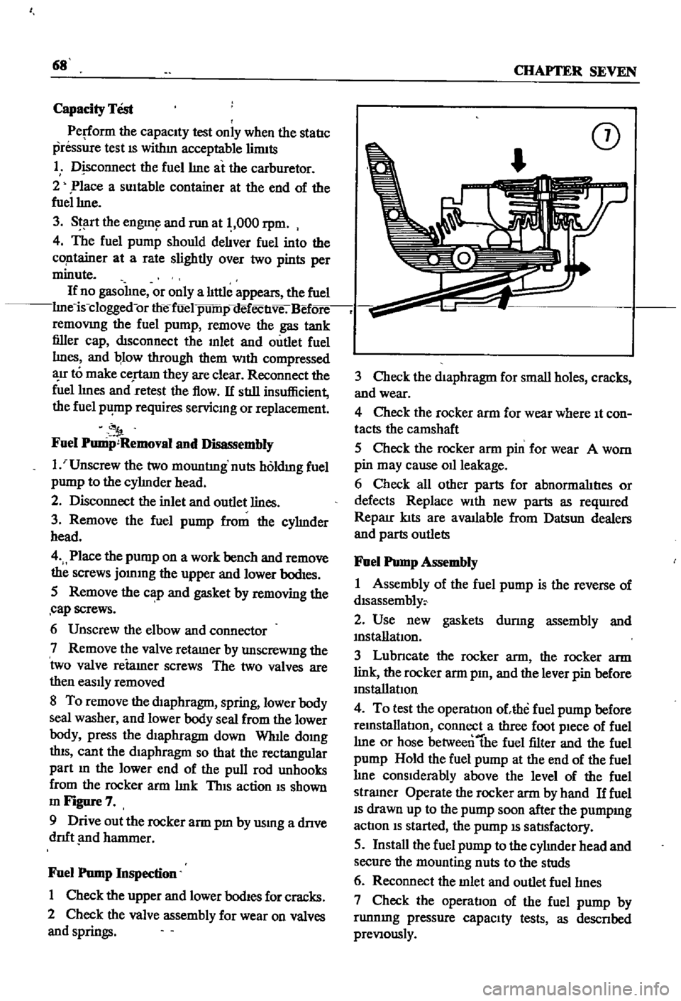
8
To
remove
the
dIaphragm
spring
lower
body
seal
washer
and
lower
body
seal
from
the
lower
body
press
the
diaphragm
down
Wh1le
domg
thIS
cant
the
dIaphragm
so
that
the
rectangular
part
m
the
lower
end
of
the
pull
rod
unhooks
from
the
rocker
arm
lmk
ThIS
action
IS
shown
mFigure7
9
Drive
out
the
rocker
arm
pm
by
usmg
a
dnve
dnft
nd
hammer
Fuel
Pump
Inspection
1
Check
the
upper
and
lower
bodIes
for
cracks
2
Check
the
valve
assembly
for
wear
on
valves
and
springs
CD
3
Check
the
diaphragm
for
small
holes
cracks
and
wear
4
Check
the
rocker
arm
for
wear
where
It
con
tacts
the
camshaft
5
Check
the
rocker
arm
pin
for
wear
A
worn
pin
may
cause
011
leakage
6
Check
all
other
parts
for
abnormalItIes
or
defects
Replace
With
new
parts
as
reqUlred
Reparr
kIts
are
available
from
Datsun
dealers
and
parts
outlets
Fuel
Pump
Assembly
1
Assembly
of
the
fuel
pump
is
the
reverse
of
dlsassembly
2
Use
new
gaskets
durmg
assembly
and
mstanatIon
3
Lubncate
the
rocker
arm
the
rocker
arm
link
the
rocker
arm
pm
and
the
lever
pin
before
mstallatIon
4
To
test
the
operatIon
ohhe
fuel
pump
before
remstallatlOn
connect
a
three
foot
pIece
of
fuel
lme
or
hose
betweentbe
fuel
filter
and
the
fuel
pump
Hold
the
fuel
pump
at
the
end
of
the
fuel
lme
conSIderably
above
the
level
of
the
fuel
stramer
Operate
the
rocker
arm
by
hand
If
fuel
IS
drawn
up
to
the
pump
soon
after
the
pumpmg
actIon
IS
started
the
pump
IS
satIsfactory
5
Install
the
fuel
pump
to
the
cylmder
head
and
secure
the
mounting
nuts
to
the
studs
6
Reconnect
the
mlet
and
outlet
fuellmes
7
Check
the
operatIon
of
the
fuel
pump
by
runnmg
pressure
capaCIty
tests
as
descnbed
preVIously