1968 DATSUN 510 width
[x] Cancel search: widthPage 9 of 252
4
CHAPTER
ONE
chassIs
number
Write
the
numbers
down
and
carry
them
ill
your
wallet
Service
Hints
Throughout
thIs
manual
keep
two
conven
bons
ill
mmd
Front
refers
to
the
front
of
the
vehicle
The
left
and
nght
sides
of
the
ve
hicle
refer
to
a
person
sittIng
ill
the
car
facing
forward
For
example
the
steenng
wheelIS
on
the
left
hand
Side
All
dimensIOns
and
capacities
are
expressed
ill
units
fanuhar
to
a
Umted
States
mechaniC
such
as
illches
and
pounds
Metric
measurements
are
also
given
Metnc
tools
are
reqUITed
to
work
on
the
Datsun
CD
DATSUN
IENGINE
CAPACITY
IMAX
HP
RPM
IWHEELBASE
IENGINE
NUMBER
FAR
NO
NlSSAN
MOTOR
co
LTD
YOKOHAMA
JAPAN
TYPEI
510
1595
cc
961P
6600
rpm
mm
L
1
00988
P61
l
O
1
l
M
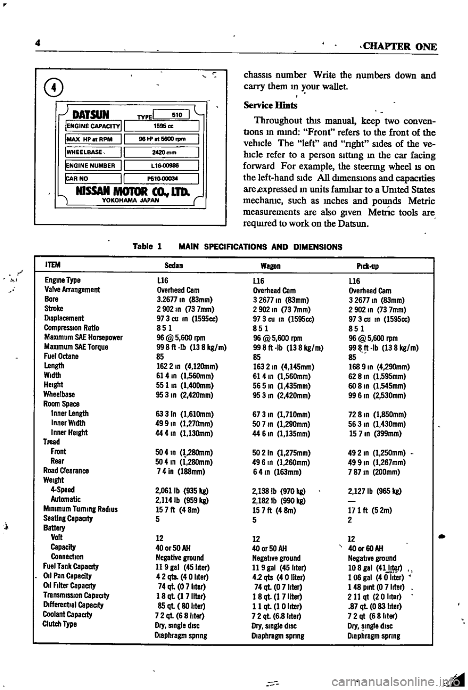
Table
1
MAIN
SPECIFICATIONS
AND
DIMENSIONS
r
ITEM
Sedan
Wagon
Plm
up
EnglDe
Type
L16
L16
L16
Valve
Arrangement
Overhead
Cam
Overhead
Cam
Overhead
Cam
Bore
3
26n
ID
83mm
3
2677
ID
83mm
3
2677
ID
83mm
Stroke
2902
ID
73
7mm
2
902
ID
73
7mm
2
902
In
73
7mm
Displacement
97
3
cu
ID
l595cc
97
3
cu
In
l595cc
97
3
cu
ID
1595cc
CompressIOn
Ratio
851
851
851
MaXimum
SAE
Hompower
96
@
5
600
rpm
96
@
5
600
rpm
96
@
5
600
rpm
MaXimum
SAE
Torque
998ft
Ib
138
kg
m
998ft
Ib
138
kg
m
9911
ft
Ib
138
kg
m
Fuel
Octane
85
85
85
Lengtb
1622
ID
4
12Omm
163
2
ID
4
I45mm
168
9
ID
4
290mm
Width
61
4
ID
l
560mm
61
4
ID
1
560mm
62
8
In
Cl
595mm
Height
55
lID
1
400mm
565
ID
Cl
435mm
60
8
ID
Cl
545mm
Wheelbase
95
3
ID
2
42Omm
95
3
ID
2
420mm
99
6
In
2
530mm
Room
Space
Inner
Length
63
3
In
1
61Omm
673
ID
1
710mm
72
8
ID
1
850mm
Inner
Width
499
ID
1
27Omm
507
ID
1
29Omm
563
In
1
430mm
Inner
Height
44
4
In
1
130mm
44
61D
1
135mm
15
7
ID
399mm
Tread
Front
50
4
ID
28Omm
502
In
1
275mm
492
In
1
250mm
Rear
504
In
1
280mm
496
In
Cl
260mm
499
ID
1
267mm
Road
Clearance
741n
l88mm
64
ID
l63mm
787
ID
200mm
Weight
4
Speed
2
0611b
935
kg
2
138
Ib
970
kg
2
127
Ib
965
kg
Automatic
2
114Ib
959
kg
2
182
Ib
990
kg
Minimum
Turning
RadiUS
157ft
48m
157ft
48m
171
ft
52m
Seating
Capaaty
5
5
2
Battery
Volt
12
12
12
Capacity
400rSOAH
400r50AH
40
or
60
AH
Connection
Negative
ground
Negative
ground
Negative
ground
Fuel
Tank
Capaaty
11
9
gal
45
liter
11
9
gal
45
liter
108
gal
41J
r
011
Pan
Capacity
42
qts
40
liter
4
2
qb
40
liter
1
06
gal
40
Iller
011
Filter
Capaaty
74
ql
07
liter
74
ql
0
7
liter
1
48
Pint
0
7
liter
Transmission
Capaaty
1
8
ql
1
7
liter
18
ql
1
7
Iller
2
11
qt
20
Iller
Dlflerenbal
Capaaty
85
ql
80
liter
11
ql
1
0
liter
87
ql
0
83
lIter
Coolant
Capaaty
7
2
ql
6
8
liter
7
2
ql
6
8
lIter
7
2
qt
6
8
Iller
Clutch
Type
Dry
Single
diSC
Dry
slDgle
diSC
Dry
slDgle
diSC
Draphragm
spnng
Diaphragm
spnng
Diaphragm
spnng
l
Page 57 of 252
52
CHAPTER
SIX
@
1oI
DlA
IlIA
AU
Al
I
2
1I
a
1I
1
6
L
us
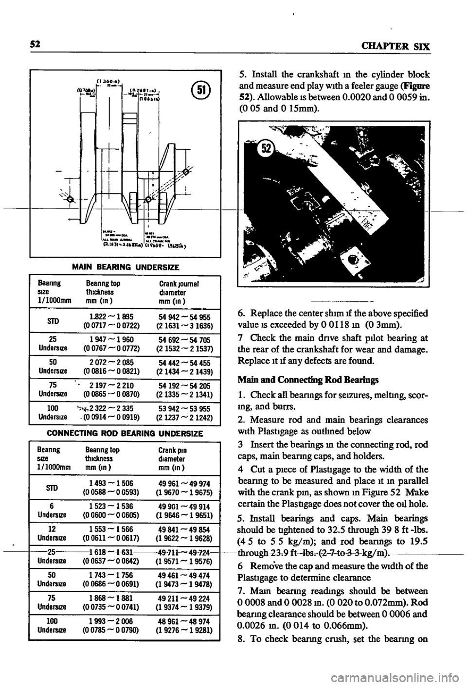
MAIN
BEARING
UNDERSIZE
Beanng
Beanng
top
Crank
Journal
sIZe
thickness
diameter
1
I000mm
mm
In
mm
In
STD
1
822
les5
54
942
54
955
0
0717
0
0722
2
1631
3
1636
25
1947
1960
54
692
54
705
Undersize
0
0767
0
0772
2
1532
2
1537
50
2072
2085
54
442
54
455
UndersIZe
00816
0
0821
2
1434
2
1439
75
2197
2
210
54
192
54
205
UndersIZe
0
0865
0
0870
2
1335
2
1341
100
2
322
2
335
53
942
53
955
UndersIZe
00914
0
0919
2
1237
2
1242
CONNECTING
ROD
BEARING
UNDERSIZE
Beanng
Beanng
top
Crank
pin
SIZe
thickness
diameter
l
loo0mm
mm
In
mm
In
STD
1493
1506
49961
49
974
0
0588
0
0593
1
9670
1
9675
6
1523
1536
49901
49
914
Undersize
0
0600
0
0605
1
9646
1
9651
12
1553
1566
49841
49
854
UndersIZe
00611
0
0617
1
9622
1
9628
25
1
618
1
631
49
711
49
724
UndersJZ8
0
0637
0
0642
1
9571
1
9576
50
1743
1756
49461
49
474
UndersIZe
00686
00691
1
9473
1
9478
75
1868
1881
49
211
49
224
UndelSlZ8
00735
0
0741
1
9374
1
9379
100
1993
2006
48
961
48
974
UndersIZe
0
0785
0
0790
1
9276
1
9281
5
Install
the
crankshaft
m
the
cylinder
block
and
measure
end
play
WIth
a
feeler
gauge
Figure
52
Allowable
IS
between
0
0020
and
0
0059
in
005
and
0
15mm
6
Replace
the
center
shIm
If
the
above
specified
value
IS
exceeded
by
0
0118
m
0
3mm
7
Check
the
main
dnve
shaft
puot
bearing
at
the
rear
of
the
crankshaft
for
wear
and
damage
Replace
It
If
any
defects
are
found
Main
and
Connecting
Rod
Bearings
1
Check
all
beanngs
for
seIZUres
meltIng
scor
mg
and
burrs
2
Measure
rod
and
main
bearings
clearances
WIth
PlastIgage
as
outhned
below
3
Insert
the
bearings
m
the
connecting
rod
rod
caps
main
beanng
caps
and
holders
4
Cut
a
pIece
of
PlastIgage
to
the
width
of
the
beanng
to
be
measured
and
place
It
m
parallel
with
the
crank
pm
as
shown
10
Figure
52
Make
certain
the
PlastIgage
does
not
cover
the
ou
hole
5
Install
bearings
and
caps
Main
bearings
should
be
tIghtened
to
32
5
through
398ft
lbs
45
to
55
kg
m
and
rod
beanngs
to
19
5
through
23
9
ft
lbs
2
7
to
3
3
kg
m
6
Remove
the
cap
and
measure
the
WIdth
of
the
PlastIgage
to
determine
clearance
7
Mam
beanng
readIngs
should
be
between
o
0008
and
0
0028
m
0
020
to
O
072mm
Rod
beanng
clearance
should
be
between
0
0006
and
0
0026
m
0014
to
0
066mm
8
To
check
beanng
crush
set
the
beanng
on
Page 65 of 252
60
SIX
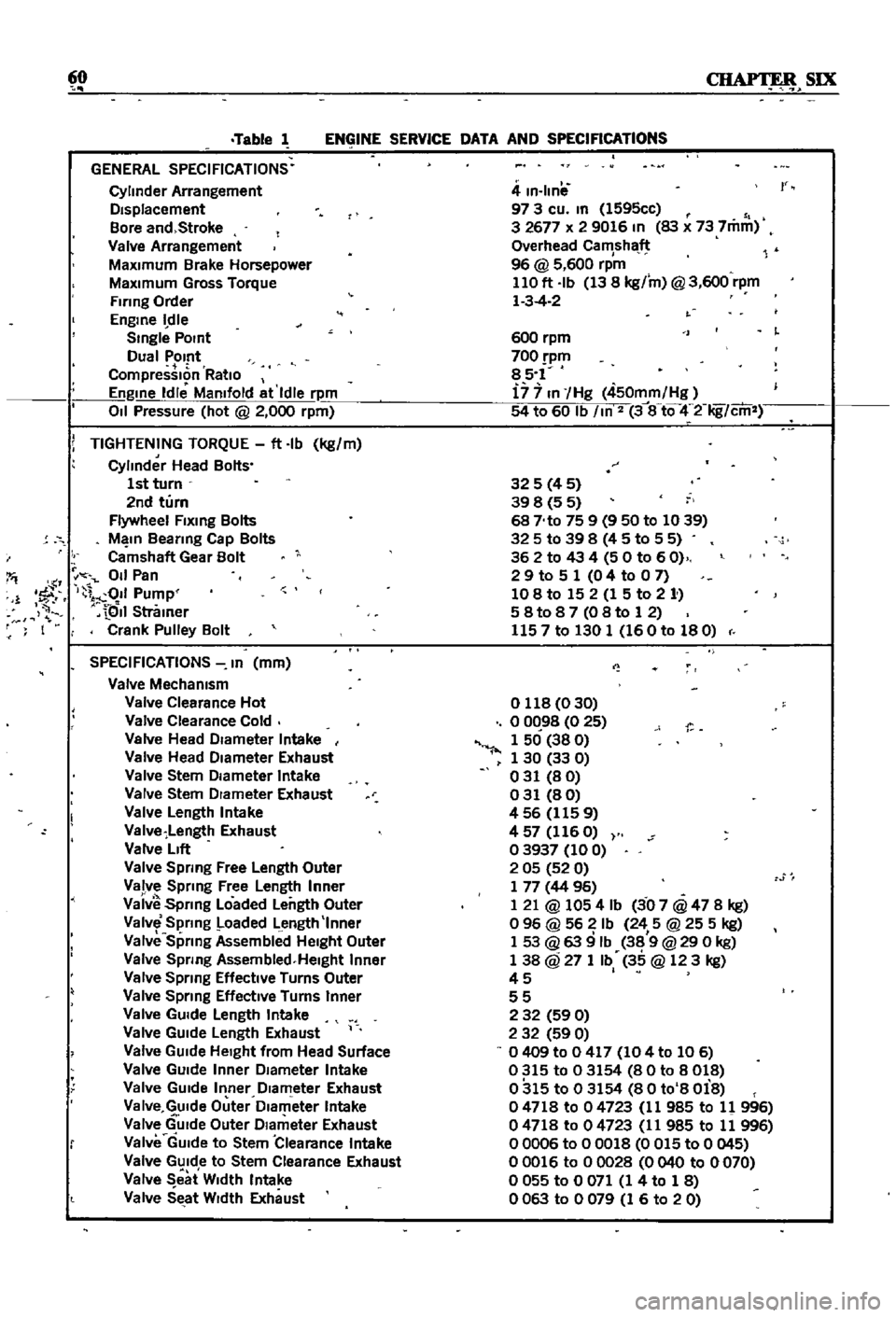
Table
1
ENGINE
SERVICE
DATA
AND
SPECIFICATIONS
GENERAL
SPECIFICATIONS
Cylinder
Arrangement
DIsplacement
Bore
and
Stroke
Valve
Arrangement
MaxImum
Brake
Horsepower
MaxImum
Gross
Torque
Firing
Order
Engme
dle
Smgle
POint
Dual
Pomt
CompressIon
RatIo
Engme
Idle
Mamfold
at
Idle
rpm
011
Pressure
hot
@
2
000
rpm
i
TIGHTENING
TORQUE
ft
Ib
kg
m
Cylinder
Head
Bolts
1st
turn
2nd
turn
Flywheel
Flxmg
Bolts
M
In
Beanng
Cap
Bolts
Camshaft
Gear
Bolt
I
011
Pan
1
1
fF
I
011
Pump
QII
Stramer
F
I
Crank
Pulley
Bolt
SPECIFICATIONS
In
mm
Valve
Mechamsm
Valve
Clearance
Hot
Valve
Clearance
Cold
Valve
Head
DIameter
Intake
Valve
Head
DIameter
Exhaust
Valve
Stem
DIameter
Intake
Valve
Stem
DIameter
Exhaust
Valve
Length
Intake
Valve
Length
Exhaust
Valve
LIft
Valve
Spring
Free
Length
Outer
Valve
Sprmg
Free
Length
Inner
Vaiv
Spnng
Loaded
Length
Outer
Valve
Spring
Loaded
Length
Inner
Valve
Sprmg
Assembllld
HeIght
Outer
Valve
Spnng
Assembled
Helght
Inner
Valve
Spnng
Effective
Turns
Outer
Valve
Sprmg
EffectIve
Turns
Inner
Valve
GUIde
Length
Intake
Valve
GUIde
Length
Exhaust
Valve
GUIde
HeIght
from
Head
Surface
Valve
GUIde
Inner
DIameter
Intake
Valve
GUIde
Inner
DIameter
Exhaust
Va
Ive
GUIde
Outer
Dlam
eter
Intake
Valve
GUIde
Outer
DIameter
Exhaust
Valve
GUIde
to
Stem
Clearance
Intake
Valve
GUIde
to
Stem
Clearance
Exhaust
Valve
eat
W
dth
Intake
Valve
SEtat
WIdth
Exhaust
4
m
Ilnil
97
3
cu
m
1595cc
3
2677
x
2
9016
In
83
x
73
7mm
Overhead
Camshaft
96
@
5
600
rpm
110
ft
Ib
13
8
kg
m
@
3
600
rpm
1
3
4
2
r
600
rpm
700
pm
85
1
i7
7
In
Hg
450mm
Hg
54
to
60
Ib
m
2
3
8
tQ
4
2
Iig
cm
325
4
5
39
8
5
5
68
No
75
9
9
50
to
1039
325
to
39
8
4
5
to
5
5
362
to
43
4
50
to
60
2
9
to
5
1
0
4
to
0
7
108
to
15
2
1
5
to
2
1
58t087
08to
12
1157
to
130
1
160
to
180
o
118
0
30
o
0C
98
0
25
1
50
38
0
1
30
33
0
031
80
031
80
456
1159
4
57
116
O
03937
100
2
05
52
0
1
77
44
96
1
21
@
1054
Ib
3
07
@
47
8
kg
o
96
@
56
Ib
24
5
@
25
5
kg
1
53
@
63
9
Ib
38
9
@
29
0
kg
1
38
@
27
1
Ib
35
@
123
kg
45
I
55
2
32
59
0
2
32
59
0
0409
to
0
417
104
to
106
0315
to
03154
80
to
8018
0315
to
03154
80
to
8
Oi8
04718
to
04723
11
985
to
11
996
04718
to
04723
11
985
to
11
996
00006
to
00018
0
015
to
0
045
00016
to
00028
0040
to
0070
o
055
to
0
071
1
4
to
1
8
0063
to
0079
1
6
to
20
Page 95 of 252
90
CHAPTER
EIGHT
degrees
C
The
maXImum
WIdth
of
the
thermo
stat
openIng
should
be
0315
In
8mm
3
If
the
thermostat
IS
defectIve
or
If
you
have
an
doubts
about
It
mstall
a
new
one
4
When
Installmg
the
thermostat
m
the
hous
Ing
be
certaIn
to
place
the
spnng
end
down
Coat
both
SIdes
of
the
gasket
WIth
sealer
to
pre
vent
leaks
and
tIghten
the
mountlng
nuts
securely
RADIATOR
The
radIator
IS
of
conventional
desIgn
A
draIn
cock
IS
proVIded
at
the
bottom
back
to
perrmt
drainIng
The
system
IS
pressurized
and
the
rehef
valve
incorporated
In
the
filler
cap
mamtains
the
pressure
at
approximately
12
8
Ib
in
0
9
kg
cm
Coolant
capacity
is
1
691
gallons
6
4
lIters
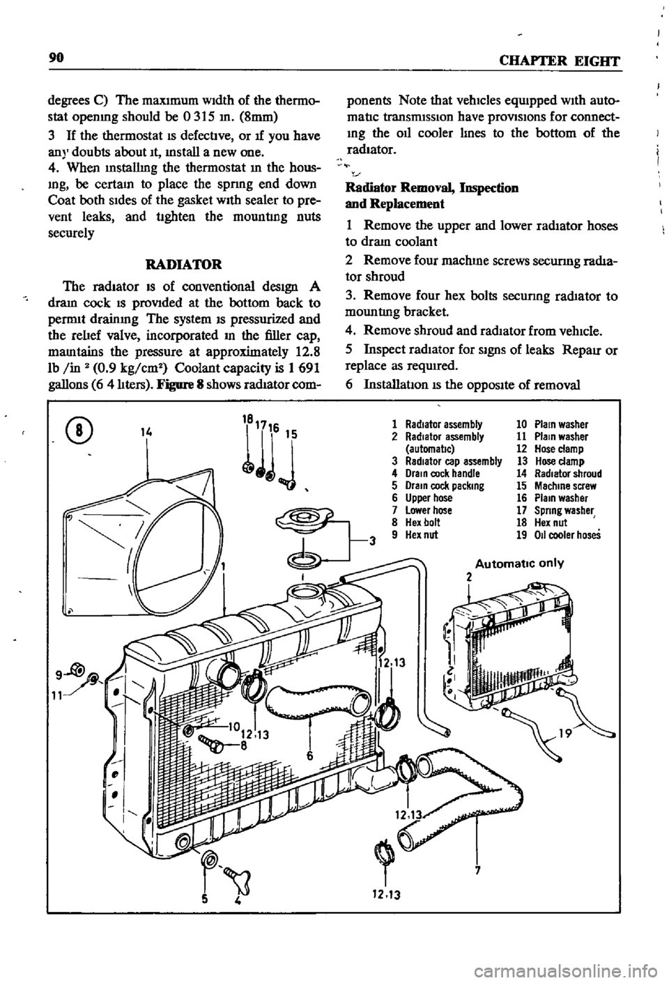
Figure
8
shows
radIator
com
ponents
Note
that
vehicles
equIpped
WIth
auto
matIc
transmISSIon
have
provlSlons
for
connect
Ing
the
011
cooler
lInes
to
the
bottom
of
the
radiator
Radiator
Removal
Inspection
and
Replacement
1
Remove
the
upper
and
lower
radIator
hoses
to
draIn
coolant
2
Remove
four
machme
screws
securmg
radIa
tor
shroud
3
Remove
four
hex
bolts
secunng
rad1ator
to
mountlng
bracket
4
Remove
shroud
and
radIator
from
vehIcle
5
Inspect
radIator
for
SignS
of
leaks
RepaIr
or
replace
as
required
6
InstallatIon
IS
the
OppOSIte
of
removal
CD
14
1
Radiator
assembly
10
Plain
washer
2
Radiator
assembly
11
Plain
washer
automal1c
12
Hose
clamp
3
RadIator
cap
assembly
13
Hose
clamp
4
Drain
cock
handle
14
Radiator
shroud
5
Drain
cock
packing
15
Machine
screw
6
Upper
hose
16
Plain
washer
7
Lower
hose
17
Spring
washer
8
Hex
bolt
18
Hex
nut
9
Hex
nut
19
011
cooler
hoses
Automatic
only
2
i
7
1213
Page 184 of 252
FRONT
AXLE
FRONT
SUSPENSION
AND
STEERING
179
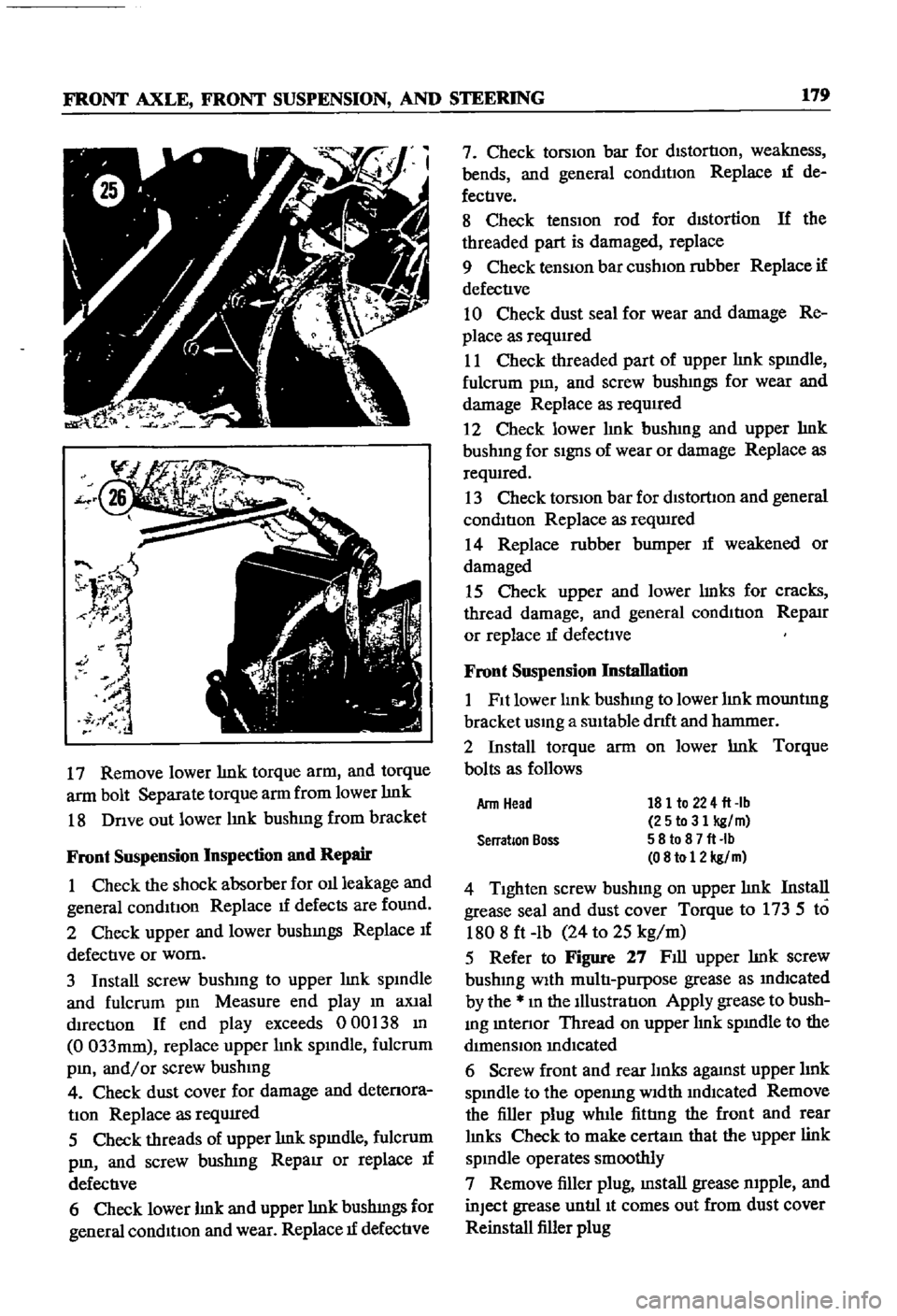
17
Remove
lower
lmk
torque
arm
and
torque
arm
bolt
Separate
torque
arm
from
lower
lmk
18
Dnve
out
lower
lmk
bushmg
from
bracket
Front
Suspension
Inspection
and
Repair
1
Check
the
shock
absorber
for
011
leakage
and
general
conditIon
Replace
1f
defects
are
found
2
Check
upper
and
lower
bushmgs
Replace
If
defective
or
worn
3
Install
screw
bushmg
to
upper
lmk
spmdle
and
fulcrum
pm
Measure
end
play
m
aXial
dIrection
If
end
play
exceeds
000
38
m
0
033mm
replace
upper
lmk
spmdle
fulcrum
pm
and
or
screw
bushmg
4
Check
dust
cover
for
damage
and
detenora
tIon
Replace
as
reqUIred
5
Check
threads
of
upper
lmk
spmdle
fulcrum
pm
and
screw
bushmg
RepaIr
or
replace
If
defective
6
Check
lower
lmk
and
upper
lmk
bushmgs
for
general
condition
and
wear
Replace
1f
defective
7
Check
torsion
bar
for
distortion
weakness
bends
and
general
conmtIon
Replace
If
de
fectIve
8
Check
tensIOn
rod
for
dIStortion
If
the
threaded
part
is
damaged
replace
9
Check
tenSiOn
bar
cushIOn
rubber
Replace
if
defective
10
Check
dust
seal
for
wear
and
damage
Re
place
as
requIred
11
Check
threaded
part
of
upper
lmk
spmdle
fulcrum
pm
and
screw
bushmgs
for
wear
and
damage
Replace
as
required
2
Check
lower
hnk
bushmg
and
upper
hnk
bushmg
for
SignS
of
wear
or
damage
Replace
as
reqwred
13
Check
torsIOn
bar
for
dlstorllon
and
general
condition
Replace
as
reqwred
14
Replace
rubber
bumper
If
weakened
or
damaged
15
Check
upper
and
lower
lmks
for
cracks
thread
damage
and
general
condition
RepaIr
or
replace
If
defectIve
Front
Suspension
Installation
1
Fit
lower
lmk
bushmg
to
lower
lmk
mountmg
bracket
usmg
a
SUItable
drlft
and
hanmIer
2
Install
torque
arm
on
lower
lmk
Torque
bolts
as
follows
181
to
224
fl
lb
25to31
kg
m
58
to
8
7
fl
Ib
08
to
12
kg
m
4
Tighten
screw
bushmg
on
upper
lmk
Install
grease
seal
and
dust
cover
Torque
to
173
5
to
1808
ft
lb
24
to
25
kg
m
5
Refer
to
Figure
27
Fill
upper
lmk
screw
bushmg
With
multi
purpose
grease
as
mdlcated
by
the
m
the
Illustration
Apply
grease
to
bush
mg
mtenor
Thread
on
upper
lmk
spmdle
to
the
dimenSIOn
mdIcated
6
Screw
front
and
rear
lInks
agaJnst
upper
hnk
spmdle
to
the
openmg
Width
mdlcated
Remove
the
filler
plug
while
fittIng
the
front
and
rear
lmks
Check
to
make
cectam
that
the
upper
link
spmdle
operates
smoothly
7
Remove
filler
plug
mstall
grease
mpple
and
inJect
grease
untIl
It
comes
out
from
dust
cover
Reinstall
filler
plug
Arm
Head
Serration
Boss
Page 208 of 252
BRAKES
203
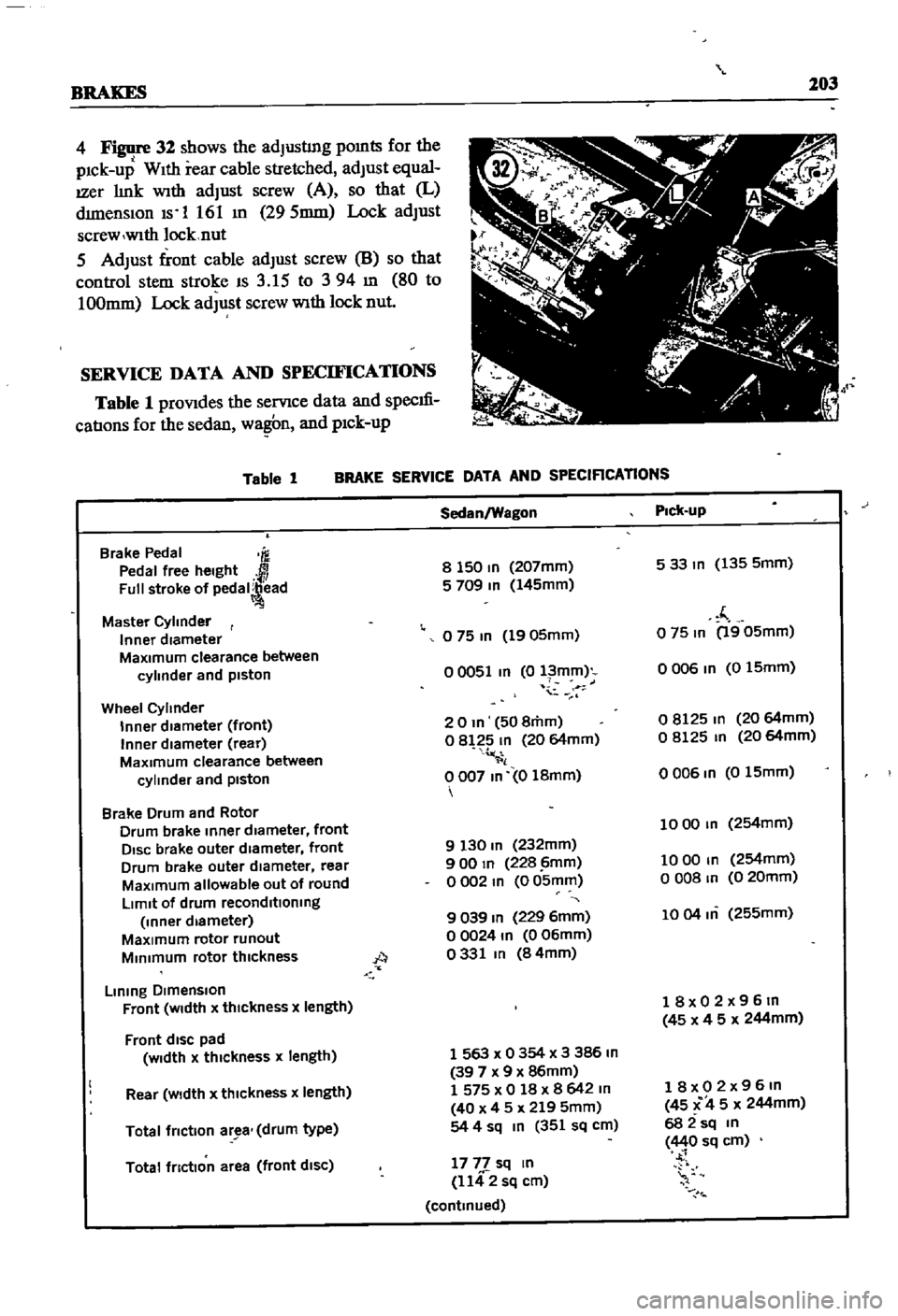
4
32
shows
the
adJusting
pomts
for
the
pick
up
With
rear
cable
stretched
adJust
equal
IZer
link
With
adJust
screw
A
so
that
L
dimensiOn
Is
1
161
m
295mm
Lock
adJust
screw
wlth
locknut
5
AdJust
front
cable
adJust
screw
8
so
that
control
stem
stroke
IS
3
15
to
394
m
80
to
100mm
Lock
adJust
screw
With
lock
nut
SERVICE
DATA
AND
SPECIFICATIONS
Table
1
prOVides
the
servIce
data
and
specm
catIons
for
the
sedan
wa
n
and
pick
up
Table
1
BRAKE
SERVICE
DATA
AND
SPECIRCATlONS
Brake
Pedal
m
Pedal
free
height
Full
stroke
of
pedal
ead
Master
Cylinder
Inner
diameter
MaXImum
clearance
between
cylinder
and
piston
Wheel
Cylinder
Inner
diameter
front
Inner
diameter
rear
MaXimum
clearance
between
cylinder
and
piston
Brake
Drum
and
Rotor
Drum
brake
Inner
diameter
front
DISC
brake
outer
diameter
front
Drum
brake
outer
diameter
rear
MaXimum
allowable
out
of
round
LImit
of
drum
reconditioning
Inner
diameter
MaXimum
rotor
runout
MInimum
rotor
thickness
A
Lining
DImenSion
Front
WIdth
x
thIckness
x
length
Front
dISC
pad
Width
x
thickness
x
length
Rear
Width
x
thickness
x
length
Total
friction
ar
a
drum
type
Total
friction
area
front
diSC
Sedan
Wagon
Pick
up
8
150
In
207mm
533m
135
5mm
5
709
In
145mm
f
o
75
In
1905mm
o
75
In
1905mm
00051
In
0
l
mm
o
006
In
0
15mm
i
20m
508mm
08125
m
20
64mm
o
8
2
In
20
64mm
o
8125
In
20
64mm
il
0007
In
0
18mm
0006
In
015mm
1000
In
254mm
9
130
In
232mm
900
In
228
imm
1000
In
254mm
o
002
m
0
05mm
o
008
In
0
20mm
9
039
In
229
6mm
1004
m
255mm
00024
In
006mm
0331
In
84mm
18x02x96m
45
x
4
5
x
244mm
1
563
x
0
354
x
3
386
In
39
7
x
9
x
86mm
1
575
x
0
18
x
8
642
m
40
x
4
5
x
219
5mm
54
4
sq
In
351
sq
cm
18x02x96m
45
C
4
5
x
244mm
682sq
m
440
sq
cm
1777
sq
In
1142
sq
cm
continued