1968 DATSUN 510 ECO mode
[x] Cancel search: ECO modePage 3 of 252
CON1EN1S
CHAPTER
ONE
GENERAL
INFORMATION
Introduction
Model
Identification
CHAPTER
TWO
PERIODIC
MAINTENANCE
RoutIne
checks
Pen
odic
checks
CHAPTER
THREE
TROUBLESHOOTING
EqUIpment
Starter
ChargIng
system
EngIne
Igmtlon
system
Fuel
system
Exhaust
emIssIon
control
CHAPTER
FOUR
ENGINE
AND
IGNITION
TUNE
UP
EqUIpment
Battery
Spark
plugs
DIstrIbutor
Igmtlon
timIng
CHAPTER
FIVE
ENGINE
LUBRICATION
SYSTEM
Descnptlon
Lubncation
cIrcuIt
SpecIficatiOns
and
dImensIons
EngIne
lubncation
and
maIntenance
Recommended
lubncants
Clutch
TransmIssiOn
Brakes
Steenng
and
suspension
TIre
wear
analysIs
Wheel
balancIng
Idle
speed
and
Idle
mIXture
Dwell
angle
setting
CompressIon
test
Valve
clearance
adjustment
AddlllOnal
checks
Oil
pump
I
6
t
1
4
V
9
t
1
20
27
Page 6 of 252
CHAPTER
ONE
GENERAL
INFORMATION
This
manual
provides
maintenance
informa
tIon
on
the
Datsun
510
Series
and
521
Series
of
vehlcles
The
510
Series
includes
the
two
door
sedan
four
door
sedan
and
station
wagon
The
521
Senes
IS
the
pIck
up
truck
Coverage
is
from
1968
through
1972
models
All
models
use
the
L16
engme
a
96
horse
power
four
cylmder
overhead
camshaft
design
The
510
has
a
fully
synchronized
four
speed
manual
or
three
speed
automatic
transmisSIon
The
521
has
a
four
speed
manual
transmission
only
In
1972
horsepower
ratIng
was
lowered
to
92
horsepower
due
to
changes
m
emission
control
device
requirements
Figure
1
is
an
over
all
view
of
the
four
door
sedan
Figure
2
shows
the
station
wagon
and
Figure
3
illustrates
the
pick
up
truck
Over
the
years
the
510
and
521
series
have
remained
essentIally
the
same
with
the
excep
tion
of
changes
to
the
emISsion
control
systems
and
overall
body
stylmg
In
this
manual
every
effort
has
been
made
to
pinpoint
significant
c
if
ferences
between
model
years
The
use
of
SpecIal
tools
and
test
equipment
has
been
avoided
wherever
possible
When
necessary
special
tools
and
test
equipment
are
illustrated
either
in
actual
use
or
alone
A
well
equipped
mecharuc
may
find
he
can
substitute
similar
tools
or
make
his
own
to
fulfill
a
e
Ii
ment
Recommendations
are
occasionally
made
to
refer
servIce
or
mamtenance
to
a
Datsun
dealer
or
a
SpecIaliSt
in
a
specIfied
field
In
these
cases
work
WIll
probably
be
done
more
qUlckly
and
economIcally
than
if
the
mecharuc
performs
them
himself
MODEL
IDENTIFICATION
Body
Number
Plate
The
body
number
IS
stamped
on
the
fire
wall
in
the
engine
compartment
The
numbers
give
the
chasSIS
model
and
serial
number
Model
Identification
Plate
The
model
Identification
plate
Figure
4
is
mounted
WIthin
the
engine
compartment
TIns
plate
gIves
engine
number
and
veh1cle
number
Engine
Identification
The
engine
identrlicatlon
marking
is
stamped
on
the
right
hand
SIde
of
the
cylinder
block
just
below
the
third
and
fourth
sp8l
k
plugs
Model
Identification
Numbel
ll
The
following
numbers
have
been
assigned
to
the
510
and
52
I
Series
vehicles
oj
Page 70 of 252
FUEL
SYSTEM
6S
CD
2
Remove
the
fuel
stramer
from
Its
mountlng
clIp
3
Replace
the
fuel
stramer
as
reqUIred
4
Reconnect
the
mtake
and
outlet
fuellmes
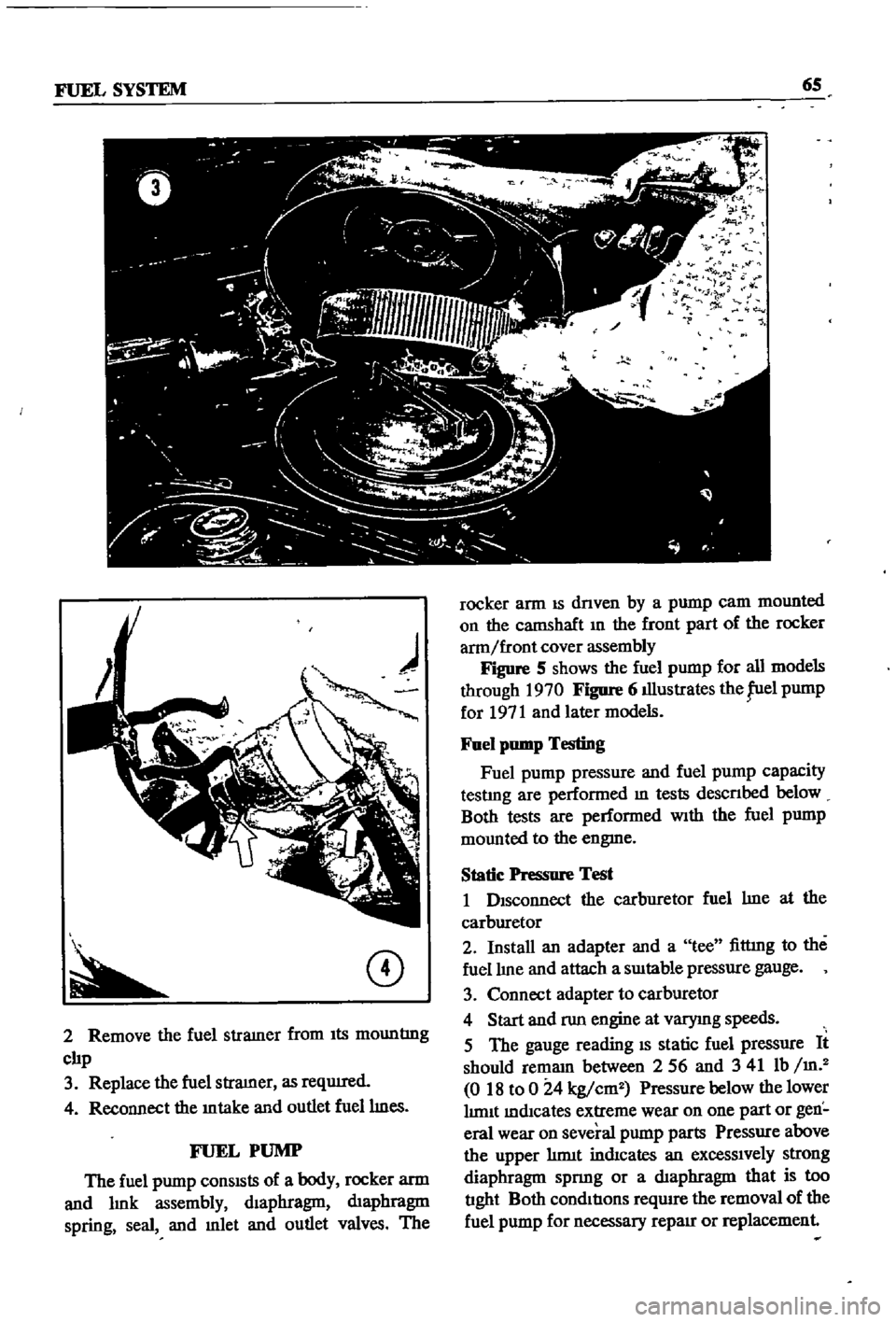
FUEL
PUMP
The
fuel
pump
conSISts
of
a
body
rocker
arm
and
lmk
assembly
dIaphragm
dIaphragm
spring
seal
and
mlet
and
outlet
valves
The
l
r
t
1
9
l
F
r
fl
rocker
arm
IS
dnven
by
a
pump
cam
mounted
on
the
catnShaft
In
the
front
part
of
the
rocker
arm
front
cover
assembly
Figure
S
shows
the
fuel
pump
for
all
models
through
1970
Figure
6
illustrates
the
fuel
pump
for
1971
and
later
models
Fuel
pump
Testing
Fuel
pump
pressure
and
fuel
pump
capacity
testlng
are
performed
m
tests
descnbed
below
Both
tests
are
performed
With
the
fuel
pump
mounted
to
the
engme
Static
Pressure
Test
1
DIsconnect
the
carburetor
fuel
lme
at
the
carburetor
2
Install
an
adapter
and
a
tee
fittmg
to
the
fuel
lIne
and
attach
a
SUItable
pressure
gauge
3
Connect
adapter
to
carburetor
4
Start
and
run
engine
at
varymg
speeds
5
The
gauge
reading
IS
static
fuel
pressure
It
should
remam
between
256
and
341
Ib
m
2
018
to
0
24
kg
cm2
Pressure
below
thelower
lImIt
mdlcates
extreme
wear
on
one
part
or
gen
eral
wear
on
several
pump
parts
Pressure
above
the
upper
hrmt
indIcates
an
excessIvely
strong
diaphragm
spnng
or
a
dIaphragm
that
is
too
tIght
Both
condItIons
require
the
removal
of
the
fuel
pump
for
necessary
repaIr
or
replacement
Page 74 of 252
FUEL
SYSTEM
69
CARBURETOR
The
carburetor
IS
an
Hltach1
Type
DAF328
Several
varIations
are
used
dependmg
on
the
model
year
type
of
transmissIOn
and
the
emIS
SIon
control
system
The
dIfferent
models
are
the
same
as
far
as
basiC
operation
IS
concerned
Therefore
the
followmg
dISCUSSIon
covers
a
typIcal
carburetor
The
automatIc
choke
IS
used
on
automatIc
transmISSIon
and
1972
models
only
All
other
chokes
are
manual
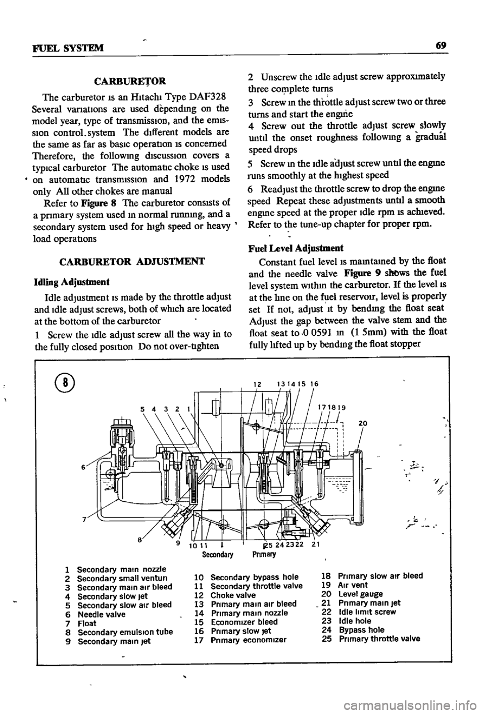
Refer
to
Figure
8
The
carburetor
conSIsts
of
a
pnmary
system
used
m
normal
runnmg
and
a
secondary
system
used
for
hIgh
speed
or
heavy
load
operatIons
CARBURETOR
ADJUSTMENT
Idling
Adjustment
Idle
adjustment
IS
made
by
the
throttle
adjust
and
Idle
adjust
screws
both
of
wh1ch
are
located
at
the
bottom
of
the
carburetor
1
Screw
the
Idle
adjust
screw
all
the
way
in
to
the
fully
closed
pOSItIon
Do
not
over
tIghten
CD
6
2
Unscrew
the
Idle
adjust
screw
approXImately
three
cor
nplete
turns
3
Screw
m
the
throttle
adjust
screw
two
or
three
turns
and
start
the
engui
e
4
Screw
out
the
throttle
adjust
screw
slowly
until
the
onset
roughness
followmg
a
gradu81
speed
drops
5
Screw
m
the
Idle
aOJust
screw
untIl
the
engme
runs
smoothly
at
the
hIghest
speed
6
Readjust
the
throttle
screw
to
drop
the
engme
speed
Repeat
these
adjustments
untIl
a
smooth
engme
speed
at
the
proper
Idle
rpm
IS
ach1eved
Refer
to
the
tune
up
chapter
for
proper
rpm
Fuel
Level
Adjustment
Constant
fuel
level
IS
mamtamed
by
the
float
and
the
needle
valve
Figure
9
sb
ws
the
fuel
level
system
wlthm
the
carburetor
If
the
level
IS
at
the
lIne
on
the
f
lel
reservOir
level
is
properly
set
If
not
adjust
It
by
bendmg
the
float
seat
Adjust
the
gap
between
the
valve
stem
and
the
float
seat
to
00591
m
1
5mm
with
the
float
fully
luted
up
by
bendmg
the
float
stopper
1213141516
20
I
h
r
1
Secondary
main
nozzle
2
Secondary
small
venturi
10
Secondary
bypass
hole
18
Primary
slow
air
bleed
3
Secondary
main
air
bleed
11
Secondary
throttle
valve
19
Air
vent
4
Secondary
slow
Jet
12
Choke
valve
20
Level
gauge
5
Secondary
slow
air
bleed
13
Primary
main
air
bleed
21
Primary
main
Jet
6
Needle
valve
14
Primary
main
nozzle
22
Idle
limit
screw
7
Float
15
Economizer
bleed
23
Idle
hole
8
Secondary
emulSion
tube
16
Primary
slow
let
24
Bypass
hole
9
Secondary
main
Jet
17
Primary
economizer
25
Primary
throttle
valve
Page 76 of 252
FUEL
SYSTEM
71
Dash
Pot
Adjustment
The
adjustment
of
the
dash
pot
IS
done
by
warmmg
up
the
engme
properly
and
checkIng
If
the
throttle
lever
touches
th
dash
pot
stem
as
the
engine
reaches
1
800
and
2
000
rpm
under
no
load
conditIons
Proper
contact
between
the
throttle
lever
and
the
dash
pot
stem
produces
a
normal
dash
pot
performance
Should
a
normal
mcrease
m
engme
speed
not
occur
adjust
the
dash
pot
as
follows
1
Loosen
the
dash
pot
locknuts
2
Rotate
the
dash
pot
nght
and
then
left
3
Adjust
the
dash
pot
so
that
the
throttle
lever
hIts
the
stem
between
1
800
and
2
000
rpm
4
Fasten
the
lock
nuts
securely
5
The
clearance
between
the
throttle
valve
and
the
throttle
chamber
wall
should
be
0
0709
m
0
8mm
or
10
degrees
In
throttle
valve
angle
MAJOR
CARBURETOR
SERVICE
PROCEDURES
A
carburetor
m
good
operatIng
condition
will
delIver
the
pr
per
gasolme
and
aIr
ratIos
for
all
engme
runnmg
speeds
A
gradual
declme
In
smoothness
response
and
power
Will
occur
as
the
carburetor
slIps
from
adjustment
and
Its
delI
cate
parts
become
dirty
and
worn
Overhaul
should
only
be
attempted
by
an
expenenced
mechanic
Accurate
calIbratIon
of
passages
and
dIS
charge
hole
reqUIre
that
extreme
care
be
taken
In
dISassembly
cleanmg
and
reassembly
Use
only
a
hIgh
grade
carburetor
cleaner
and
com
pressed
arr
to
clean
parts
and
passages
Never
use
wire
or
other
pOInted
Instruments
for
clean
ing
CalIbratIon
of
the
carburetor
will
be
af
fected
The
procedures
below
are
generally
true
for
all
models
As
an
aId
Figures
13
and
14
are
typIcal
examples
of
the
carburetors
used
Carburetor
Removal
1
Remove
the
au
cleaner
by
dIsconnectIng
all
hoses
attached
to
It
remoVmg
the
two
bolts
holdmg
the
aIr
cleaner
to
the
support
and
loos
enmg
the
band
bolt
at
the
base
of
the
aIr
cleaner
2
DIsconnect
fuellme
vacuum
Ime
and
choke
wire
u
eqUIpped
from
the
carburetor
3
Remove
the
throttle
lever
4
Remove
four
nuts
and
washers
holdmg
car
buretor
to
manIfold
5
Lift
carburetor
off
of
manuold
6
Remove
and
dIscard
carburetor
to
manuold
gasket
7
Place
carburetor
on
clean
workbench
Carburetor
Disassembly
1
The
maIn
Jets
slow
Jets
and
needle
valves
on
both
the
pnmary
and
secondary
systenIS
are
accessIble
from
outsIde
the
carburetor
Refer
to
FIgures
13
and
14
for
locatI
n
2
The
choke
chamber
can
be
detached
by
re
mOVIng
the
connectIng
rod
pump
connectIng
rod
return
sprmg
stop
pm
and
the
set
screws
I
that
hold
It
in
place
3
The
pnmary
and
secondary
emulSIon
tubes
can
be
disassembled
by
remOVIng
the
mam
air
bleeds
on
the
respectIve
SIdes
4
To
check
the
accelerator
pump
remove
the
cylInder
cover
Be
careful
not
to
lose
the
return
spnng
and
Inlet
valve
at
the
lower
part
of
the
pIston
durmg
dIsassembly
5
Detach
the
throttle
chamber
from
the
float
chamber
by
remOVIng
the
rod
lInkIng
the
dia
phragm
WIth
the
secondary
throttle
valve
and
the
four
screws
that
hold
It
However
It
IS
preferable
to
leave
the
throttle
valve
mtact
unless
absolutely
reqUired
If
It
IS
necessary
to
dlS
assemble
the
valve
It
should
be
Installed
so
that
the
secondary
throttle
valve
will
be
gap
free
OtherwIse
stable
Idle
and
good
slow
speed
performance
will
suffer
is
To
check
the
float
the
float
chamber
cover
must
be
removed
I
7
The
dIaphragm
IS
dIsassembled
by
removing
the
set
screws
holdmg
the
dIaphragm
chamber
cover
In
reassemblIng
the
diaphragm
be
careful
not
to
turn
the
edge
of
the
dIaphragm
up
8
In
dlsassemblmg
and
reassembling
the
mter
lockIng
lInks
take
care
so
that
each
lInkage
has
a
smooth
actIon
and
that
parts
are
not
forced
mto
pOSItIon
9
For
vehIcles
equipped
With
an
automatIc
choke
remove
the
brmetal
case
by
releasmg
the
set
screws
The
bimetal
1l
extremely
senSItIve
Page 81 of 252
76
CHAPTER
SEVEN
Carburetor
Assembly
Assembly
is
the
reverse
of
dISassembly
Make
certam
all
gaskets
are
mounted
flat
Be
careful
not
to
use
force
In
assembly
Make
certam
that
all
Interlock
lInks
operate
smoothly
FUEL
TANK
Description
FIgures
15
16
17
and
18
are
exploded
views
of
the
fuel
tanks
used
on
the
sedan
and
wagons
Figure
15
IS
for
sedans
through
model
year
1969
Figure
16
applIes
to
sedans
from
1970
With
evaporative
control
system
F
q
nre
17
shows
the
statIon
wagon
through
1969
Figure
18
applIes
to
the
statIon
wagon
WIth
evaporative
control
system
f
m
1970
The
fuel
tank
for
the
pIck
up
is
shown
m
Figure
19
A
fuel
return
system
from
the
carburetor
to
the
fuel
tank
keeps
fuel
from
becommg
over
heated
m
the
carburetor
float
chamber
When
the
normal
level
m
the
float
chamber
IS
exceeded
a
pressure
valve
opens
and
returns
the
excess
fuel
to
the
tank
Removal
Sedans
1
Remove
drain
plug
m
bottom
of
fuel
tank
and
drain
the
fuel
into
a
suitable
safe
contamer
2
Detach
rear
seat
and
seat
back
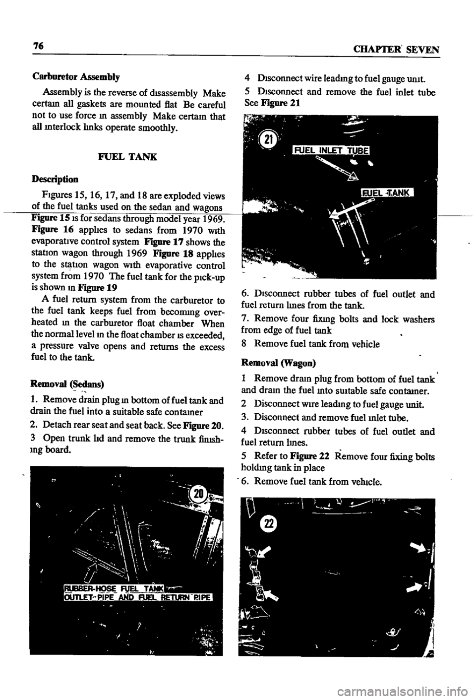
See
Figure
20
3
Open
trunk
lId
and
remove
the
trunk
finISh
mg
board
4
DIsconnect
wire
leadmg
to
fuel
gauge
umt
5
DIsconnect
and
remove
the
fuel
inlet
tube
See
Figure
21
6
DIsconnect
rubber
tubes
of
fuel
outlet
and
fuel
return
lInes
from
the
tank
7
Remove
four
fixmg
bolts
and
lock
washers
from
edge
of
fuel
tank
8
Remove
fuel
tank
from
vehicle
Removal
Wagon
1
Remove
draIn
plug
from
bottom
of
fuel
tank
and
dram
the
fuel
mto
swtable
safe
contatner
2
Disconnect
WIre
leadIng
to
fuel
gauge
unit
3
Disconnect
and
remove
fuel
mlet
tube
4
DISconnect
rubber
tubes
of
fuel
outlet
and
fuel
return
lInes
5
Refer
to
Figure
22
Remove
four
fixing
bolts
holdmg
tank
in
place
6
Remove
fuel
tank
from
veh1c1e
Page 90 of 252
COOLING
SYSTEM
8S
and
In
those
with
exhaust
and
evaporatIve
emIS
sion
control
devIces
a
fan
clutch
IS
combIned
WIth
the
thermostat
to
detect
temperature
m
the
engme
compartlnent
When
the
temperature
nses
the
thermostat
detects
the
change
an
the
fan
clutch
engages
thereby
helpmg
to
cool
the
engme
WATER
PUMP
Figure
2
page
86
IS
an
exploded
drawmg
of
the
water
pump
and
fan
assembly
for
1970
to
1971
The
top
half
of
the
IllustratIon
applIes
to
those
models
WIth
exhaust
and
evaporatIve
emiSSIOn
control
systems
The
bottom
half
covers
models
WIth
a
crankcase
emiSSIon
control
deVIce
only
Figure
3
page
87
IS
an
exploded
drawmg
of
the
water
pump
and
fan
assembly
for
1968
models
Without
exhaust
or
evaporatIve
controls
Figure
4
page
88
shows
the
1968
model
With
emISSIon
control
deVIce
As
can
be
seen
from
the
illustratIons
most
dIfferences
eXISt
withIn
the
fan
clutch
assembly
Water
Pump
Removal
1
Remove
upper
and
lower
radIator
hoses
from
the
thermostat
housmg
and
cylmder
block
re
spectIvely
Dram
coolant
from
rad1ator
and
cylInder
block
2
Loosen
the
alternator
mountlng
bolt
and
the
adjustIng
bolt
on
the
alternator
mountIng
bracket
3
Move
the
alternator
toward
the
cylinder
block
untIl
slack
IS
eVIdent
10
the
fan
belt
Re
move
fa
belt
fro
alternator
water
pump
and
crankshaft
pulley
4
It
IS
difficult
to
remove
the
water
pump
from
the
front
housmg
With
the
radiator
and
top
shroud
10
place
so
remove
them
5
Remove
the
bolts
holdmg
the
fan
assembly
to
the
water
pump
and
remove
the
fan
assembly
6
Remove
the
bolts
holdmg
the
water
pump
to
the
front
housmg
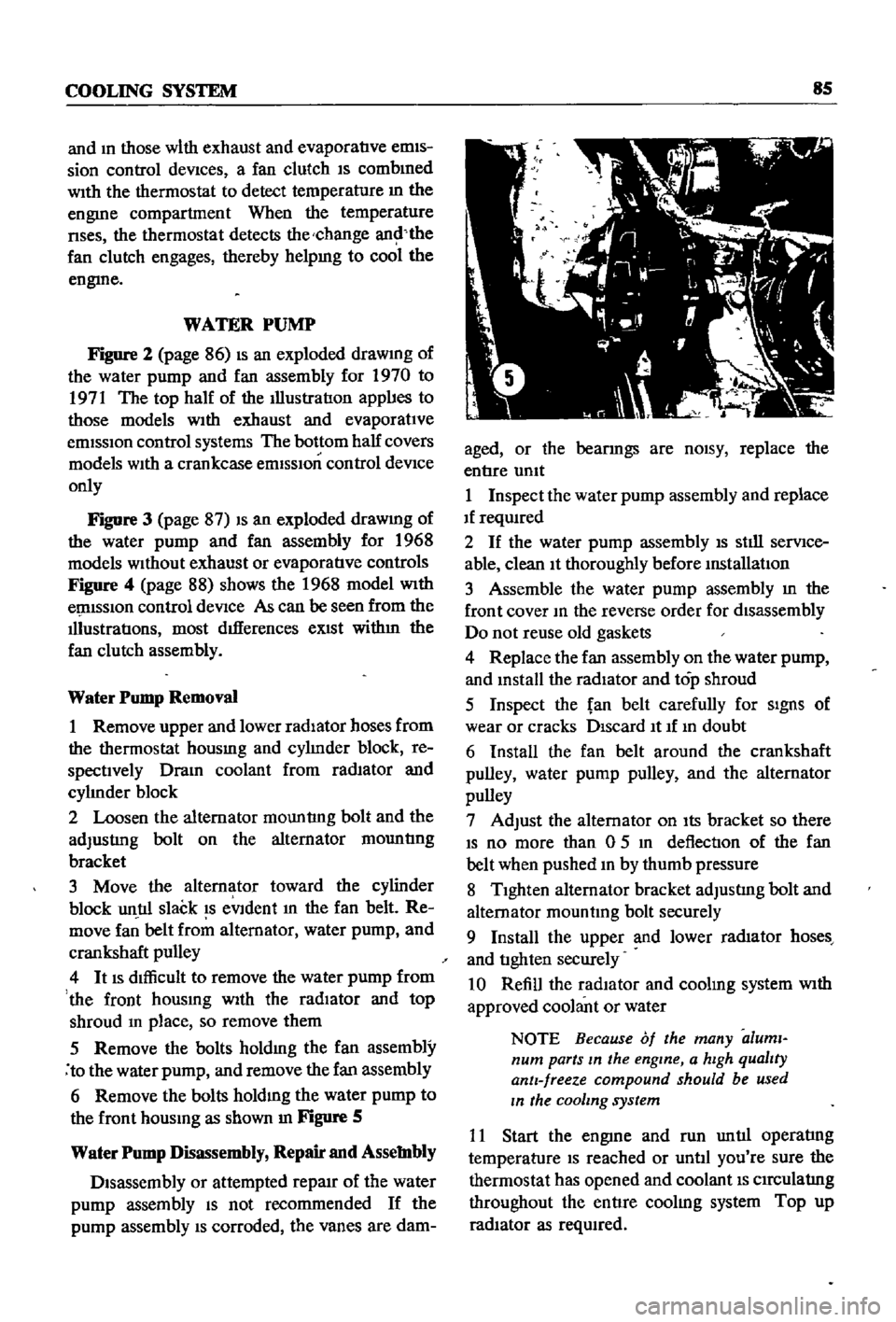
as
shown
In
Figure
S
Water
Pump
Disassembly
Repair
and
Assembly
Disassembly
or
attempted
repaIr
of
the
water
pump
assembly
IS
not
recommended
If
the
pump
assembly
IS
corroded
the
vanes
are
dam
aged
or
the
bearmgs
are
nOISY
replace
the
entIre
umt
1
Inspect
the
water
pump
assembly
and
replace
If
reqUIred
2
If
the
water
pump
assembly
IS
stIll
serVIce
able
clean
It
thoroughly
before
mstallatIon
3
Assemble
the
water
pump
assembly
m
the
front
cover
10
the
reverse
order
for
disassembly
Do
not
reuse
old
gaskets
4
Replace
the
fan
assembly
on
the
water
pump
and
mstall
the
radiator
and
top
shroud
5
Inspect
the
fan
belt
carefully
for
SIgnS
of
wear
or
cracks
DIscard
It
If
10
doubt
6
Install
the
fan
belt
around
the
crankshaft
pulley
water
pump
pulley
and
the
alternator
pulley
7
Adjust
the
alternator
on
Its
bracket
so
there
IS
no
more
than
0
5
10
deflection
of
the
fan
belt
when
pushed
10
by
thumb
pressure
8
TIghten
alternator
bracket
adjustIng
bolt
and
alternator
mountmg
bolt
securely
9
Install
the
upper
and
lower
rad1ator
hoses
and
tIghten
securely
10
Refill
the
radIator
and
coolmg
system
With
approved
coolant
or
water
NOTE
Because
of
the
many
aluml
num
parts
In
the
engine
a
hIgh
qualIty
antI
freeze
compound
should
be
used
In
the
cooling
system
11
Start
the
engme
and
run
untIl
operatIng
temperature
IS
reached
or
untIl
you
re
sure
the
thermostat
has
opened
and
coolant
IS
CIrCulatIng
throughout
the
entIre
coolIng
system
Top
up
radIator
as
reqUIred
Page 193 of 252
J
188
CHAPTER
FOURTEEN
Brake
Pedal
Installation
1
Apply
pedal
grease
to
the
pedal
shaft
sleeves
and
push
rod
cleVIS
pm
2
Installation
is
the
reverse
of
removal
3
Torque
the
fulcrum
pm
to
25
3
to
28
9
ft
lb
3
5
to
4
0
kg
m
MASTER
CYLINDER
FIgure
3
is
an
exploded
view
of
the
tandem
master
cyhnder
used
on
the
sedan
and
wagon
starting
m
1969
Earher
models
are
sinnlar
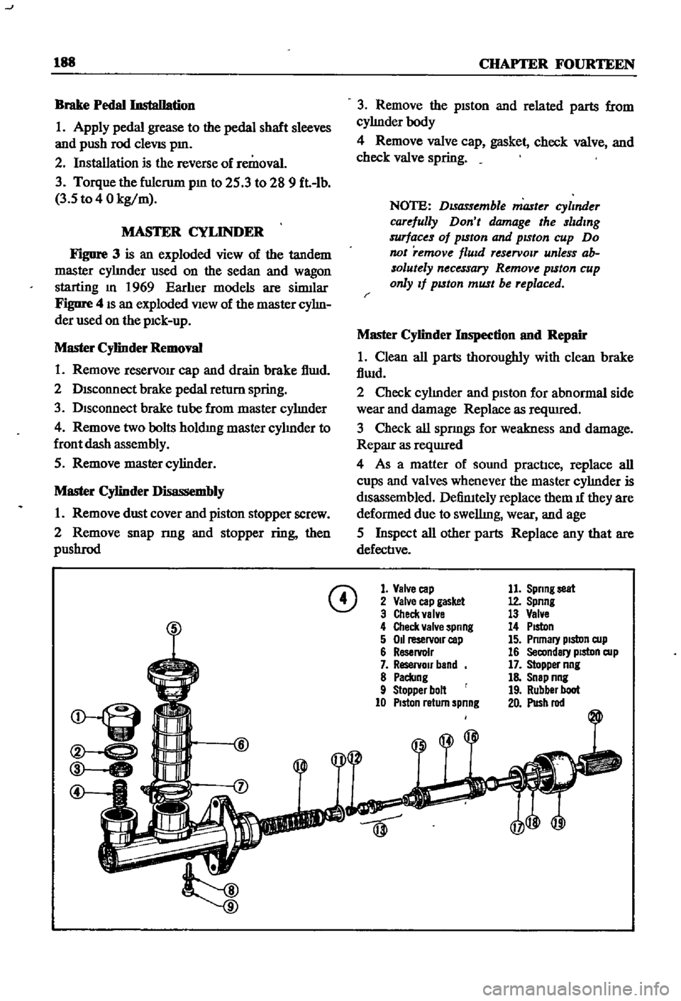
Figure
4
IS
an
exploded
View
of
the
master
cyhn
der
used
on
the
pIck
up
Master
Cylinder
Removal
1
Remove
reservOIr
cap
and
drain
brake
f1wd
2
DISconnect
brake
pedal
return
spring
3
Disconnect
brake
tube
from
master
cyhnder
4
Remove
two
bolts
holdmg
master
cyhnder
to
front
dash
assembly
5
Remove
master
cylinder
Master
Cylinder
Disassembly
1
Remove
dust
cover
and
piston
stopper
screw
2
Remove
snap
nng
and
stopper
ring
then
pllShrod
3
Remove
the
piston
and
related
parts
from
cyhnderbody
4
Remove
valve
cap
gasket
check
valve
and
check
valve
spring
NOTE
DISassemble
master
cylmder
carefully
Don
t
damage
the
slldmg
surfaces
of
pISton
and
pISton
cup
Do
not
remove
flUId
reservOlT
unless
ab
solutely
necessary
Remove
pISton
cup
only
If
pISton
must
be
replaced
r
Master
Cylinder
Inspection
nnd
Repair
1
Clean
all
parts
thoroughly
with
clean
brake
fiwd
2
Check
cyhnder
and
piston
for
abnormal
side
wear
and
damage
Replace
as
reqUIred
3
Check
all
spnngs
for
weakness
and
damage
Reparr
as
reqUIred
4
As
a
matter
of
sound
practIce
replace
all
cups
and
valves
whenever
the
master
cyhnder
is
dISassembled
DefinItely
replace
them
1f
they
are
deformed
due
to
swellmg
wear
and
age
5
Inspect
all
other
parts
Replace
any
that
are
defective
CD
1
Valve
cap
2
Valve
cap
gasket
3
Check
valve
4
Check
valve
spnng
5
011
reservoIr
cap
6
Reservoir
7
ReservOir
band
8
Paclang
9
Stopper
bolt
10
PIston
return
spnng
11
Sprmg
seat
12
Spnng
13
Valve
14
PIston
15
Pnmary
pIston
cup
16
Secondary
piston
cup
17
Stopper
nng
18
Snap
nng
19
Rubber
boot
20
Push
rod