1968 DATSUN 510 maintenance
[x] Cancel search: maintenancePage 3 of 252
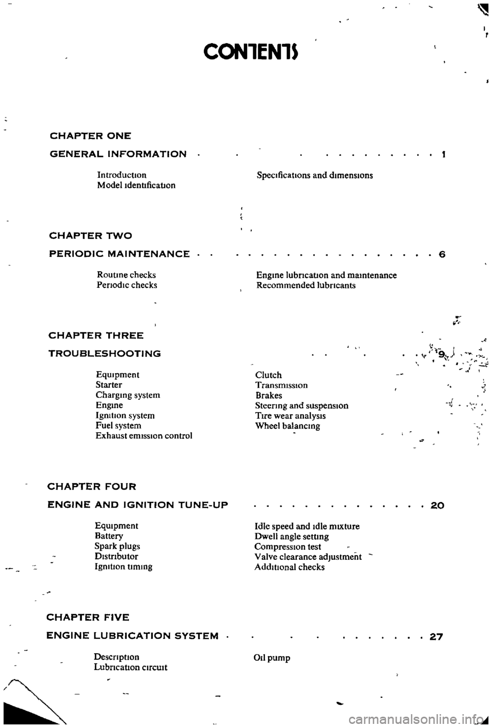
CON1EN1S
CHAPTER
ONE
GENERAL
INFORMATION
Introduction
Model
Identification
CHAPTER
TWO
PERIODIC
MAINTENANCE
RoutIne
checks
Pen
odic
checks
CHAPTER
THREE
TROUBLESHOOTING
EqUIpment
Starter
ChargIng
system
EngIne
Igmtlon
system
Fuel
system
Exhaust
emIssIon
control
CHAPTER
FOUR
ENGINE
AND
IGNITION
TUNE
UP
EqUIpment
Battery
Spark
plugs
DIstrIbutor
Igmtlon
timIng
CHAPTER
FIVE
ENGINE
LUBRICATION
SYSTEM
Descnptlon
Lubncation
cIrcuIt
SpecIficatiOns
and
dImensIons
EngIne
lubncation
and
maIntenance
Recommended
lubncants
Clutch
TransmIssiOn
Brakes
Steenng
and
suspension
TIre
wear
analysIs
Wheel
balancIng
Idle
speed
and
Idle
mIXture
Dwell
angle
setting
CompressIon
test
Valve
clearance
adjustment
AddlllOnal
checks
Oil
pump
I
6
t
1
4
V
9
t
1
20
27
Page 6 of 252
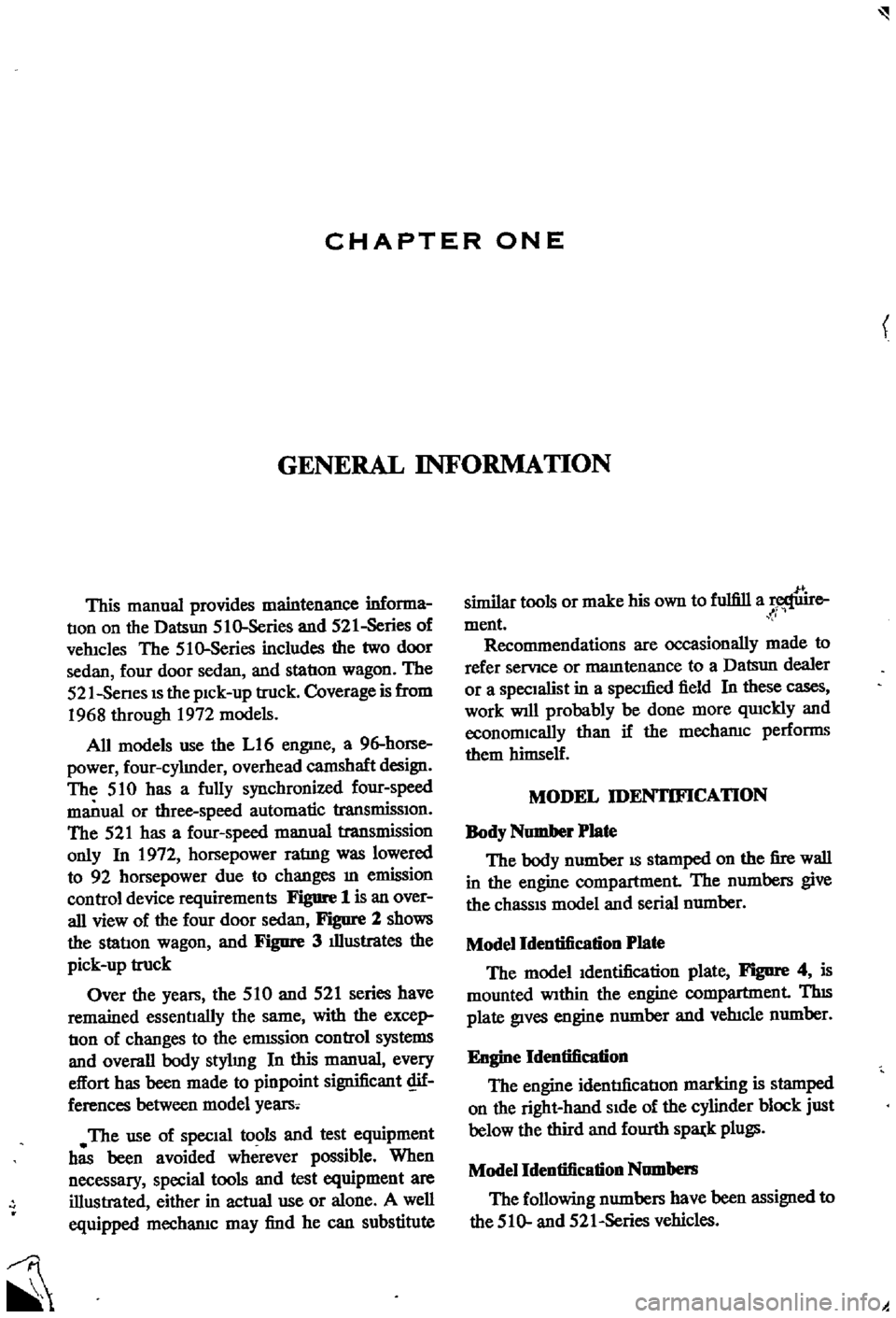
CHAPTER
ONE
GENERAL
INFORMATION
This
manual
provides
maintenance
informa
tIon
on
the
Datsun
510
Series
and
521
Series
of
vehlcles
The
510
Series
includes
the
two
door
sedan
four
door
sedan
and
station
wagon
The
521
Senes
IS
the
pIck
up
truck
Coverage
is
from
1968
through
1972
models
All
models
use
the
L16
engme
a
96
horse
power
four
cylmder
overhead
camshaft
design
The
510
has
a
fully
synchronized
four
speed
manual
or
three
speed
automatic
transmisSIon
The
521
has
a
four
speed
manual
transmission
only
In
1972
horsepower
ratIng
was
lowered
to
92
horsepower
due
to
changes
m
emission
control
device
requirements
Figure
1
is
an
over
all
view
of
the
four
door
sedan
Figure
2
shows
the
station
wagon
and
Figure
3
illustrates
the
pick
up
truck
Over
the
years
the
510
and
521
series
have
remained
essentIally
the
same
with
the
excep
tion
of
changes
to
the
emISsion
control
systems
and
overall
body
stylmg
In
this
manual
every
effort
has
been
made
to
pinpoint
significant
c
if
ferences
between
model
years
The
use
of
SpecIal
tools
and
test
equipment
has
been
avoided
wherever
possible
When
necessary
special
tools
and
test
equipment
are
illustrated
either
in
actual
use
or
alone
A
well
equipped
mecharuc
may
find
he
can
substitute
similar
tools
or
make
his
own
to
fulfill
a
e
Ii
ment
Recommendations
are
occasionally
made
to
refer
servIce
or
mamtenance
to
a
Datsun
dealer
or
a
SpecIaliSt
in
a
specIfied
field
In
these
cases
work
WIll
probably
be
done
more
qUlckly
and
economIcally
than
if
the
mecharuc
performs
them
himself
MODEL
IDENTIFICATION
Body
Number
Plate
The
body
number
IS
stamped
on
the
fire
wall
in
the
engine
compartment
The
numbers
give
the
chasSIS
model
and
serial
number
Model
Identification
Plate
The
model
Identification
plate
Figure
4
is
mounted
WIthin
the
engine
compartment
TIns
plate
gIves
engine
number
and
veh1cle
number
Engine
Identification
The
engine
identrlicatlon
marking
is
stamped
on
the
right
hand
SIde
of
the
cylinder
block
just
below
the
third
and
fourth
sp8l
k
plugs
Model
Identification
Numbel
ll
The
following
numbers
have
been
assigned
to
the
510
and
52
I
Series
vehicles
oj
Page 11 of 252
CHAPTER
TWO
PERIODIC
MAINTENANCE
To
ensure
good
performance
dependability
and
safety
regular
penodlc
maintenance
is
necessary
TIns
chapter
outlInes
routine
and
penodlc
mamtenance
for
the
average
dnver
Under
heavy
usage
semcmg
mtervals
will
be
shortened
Regular
routme
mamtenance
will
help
aVOId
expensive
repaIrs
ROUTINE
CHECKS
The
followlDg
checks
should
be
performed
at
each
fuel
stop
1
Check
engme
oil
level
Top
up
as
requrred
2
Check
radiator
coolant
level
Top
up
as
re
qwred
3
Check
battery
electrolyte
The
battery
case
IS
marked
With
upper
hrmt
and
lower
lnmt
lInes
Level
should
be
maID
tamed
between
the
IIDes
4
Check
that
the
master
cylInder
brake
flwd
reservOir
level
IS
between
the
max
and
mm
lInes
marked
on
the
plastic
case
S
Check
the
plastic
clutch
cyhnder
reservoir
level
Level
should
be
between
the
max
and
mm
lInes
6
Check
the
windsh1eld
washer
flwd
reservoir
Top
up
as
required
7
Check
tire
pressures
when
the
tIres
are
cold
Front
and
rear
tire
pressures
should
be
24
pounds
under
normal
dnving
conditions
TIre
pressure
should
be
28
pounds
for
h1gh
speed
dnvmg
conditions
8
Check
the
engIne
for
general
conditIon
Check
for
leaky
or
cracked
hoses
and
loose
wmng
9
Check
condition
of
wmdshleld
wiper
blades
PERIODIC
CHECKS
Table
1
prOVIdes
penodIc
checks
and
main
tenance
that
should
be
performed
on
a
set
schedule
Table
2
gIves
recommended
lubncants
and
Table
3
specIfies
the
grades
of
oil
that
should
be
used
Procedures
for
performmg
the
semces
are
presented
ID
vanous
chapters
of
tlus
manual
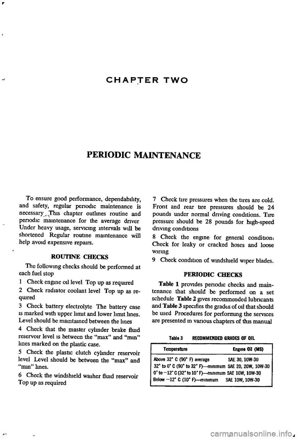
Table
3
RECOMMENDED
GRADES
OF
OIL
Temperature
Engine
on
MS
Above
32
C
90
F
average
SAE
30
IOW
30
32
to
0
C
90
to
32
F
mlmmum
SAE
20
20W
IOW
30
O
to
12
C
32
tolO
F
mlRlmum
SAE
IOW
IOW
30
Below
12
C
10
F
mlmmum
SAE
lOW
IOW
30
Page 12 of 252

PERIODIC
MAINTENANCE
7
Table
1
ENGINE
LUBRICATION
AND
MAINTENANCE
FREQUENCY
EVERY
E
E
E
E
E
E
E
Eo
00
00
00
00
00
00
00
gq
00
00
00
NO
t
r61li
0
CD
Check
engine
011
level
top
up
If
required
X
Change
engine
011
X
Lubricate
carburetor
hnkage
X
Lubricate
distributor
rotor
shaft
and
ann
shaft
X
Apply
grease
to
distributor
cam
heel
X
Check
radiator
coolant
level
X
Change
radIator
coolant
X
Change
radiator
coolant
additive
X
Check
battery
electrolyte
level
X
Check
specific
gravity
of
battery
X
Check
engine
starting
exhaust
color
X
Tighten
cyhnder
head
manifolds
and
pipe
flanges
X
Adjust
valve
clearance
X
Check
Ignition
timing
X
Tighten
carburetor
fittings
X
Check
fan
belt
tension
X
Check
for
011
pan
leakage
X
Tighten
engine
mounts
X
Check
fuel
strainer
X
Replace
fuel
strainer
X
Check
for
fuel
leaks
X
Replace
011
filter
X
Check
spark
plugs
X
Replace
spark
plugs
X
Check
dlstnbutor
cap
rotor
and
POints
X
Adjust
engine
Idle
speed
X
Check
air
cleaner
fittings
X
Clean
011
filler
cap
X
Clean
battery
cables
and
terminals
X
Check
alternator
and
voltage
regulator
function
X
Check
starter
motor
function
X
Replace
aIr
cleaner
element
X
Check
fuel
pump
function
X
Check
cyhnder
compressIon
X
Clean
carburetor
Jets
and
float
chamber
X
Check
dlstnbutor
condenser
X
Check
crankcase
ventilation
control
valve
X
Page 119 of 252
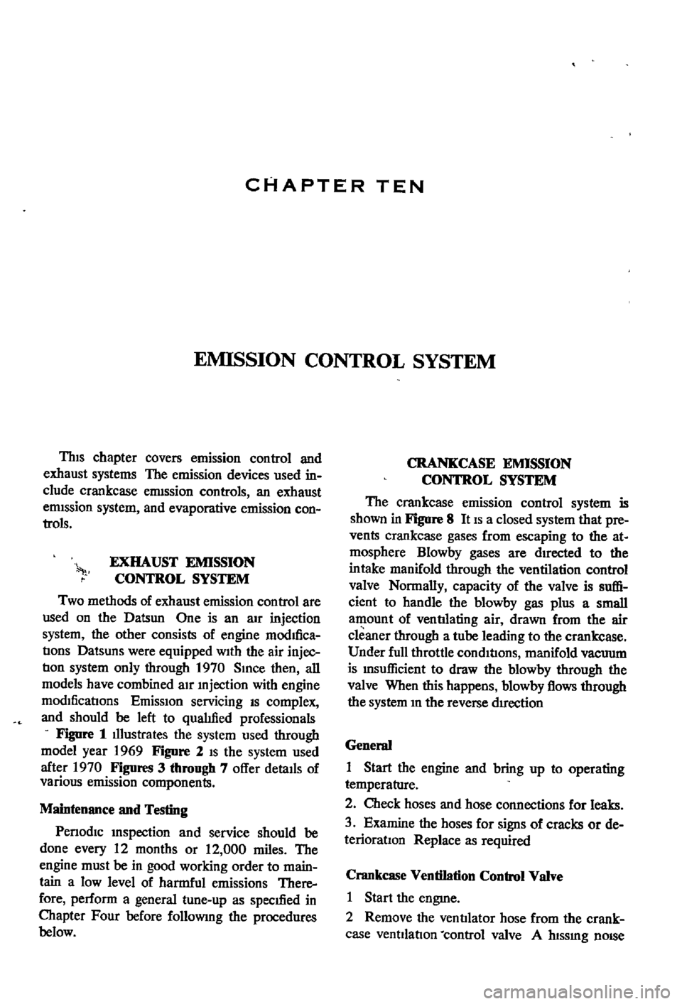
CHAPTER
TEN
EMISSION
CONTROL
SYSTEM
ThIs
chapter
covers
emission
control
and
exhaust
systems
The
emission
devices
used
in
clude
crankcase
ermssion
controls
an
exhaust
ermssion
system
and
evaporative
emission
con
trols
EXHAUST
EMISSION
CONTROL
SYSTEM
Two
methods
of
exhaust
emission
control
are
used
on
the
Datsun
One
is
an
aIr
injection
system
the
other
consists
of
engine
modifica
tIons
Datsuns
were
equipped
With
the
air
injec
tIon
system
only
through
1970
SInce
then
all
models
have
combined
aIr
mjection
with
engine
modIficatIons
EmisSIon
servicing
IS
complex
and
should
be
left
to
qualIfied
professionals
Figure
1
Illustrates
the
system
used
through
model
year
1969
Figure
2
IS
the
system
used
after
1970
Figures
3
through
7
offer
detaIls
of
various
emission
components
Maintenance
and
Testing
Penodlc
mspection
and
service
should
be
done
every
12
months
or
12
000
miles
The
engine
must
be
in
good
working
order
to
main
tain
a
low
level
of
harmful
emissions
There
fore
perform
a
general
tune
up
as
spec1fied
in
Chapter
Four
before
followmg
the
procedures
below
CRANKCASE
EMISSION
CONTROL
SYSTEM
The
crankcase
emission
control
system
is
shown
in
FlgDre
8
It
IS
a
closed
system
that
pre
vents
crankcase
gases
from
escaping
to
the
at
mosphere
Blowby
gases
are
dIrected
to
the
intake
manifold
through
the
ventilation
control
valve
Normally
capacity
of
the
valve
is
suffi
cient
to
handle
the
blowby
gas
plus
a
small
amount
of
ventIlating
air
drawn
from
the
air
cleaner
through
a
tube
leading
to
the
crankcase
Under
fun
throttle
condItIons
manifold
vacuum
is
Insufficient
to
draw
the
blowby
through
the
valve
When
this
happens
b10wby
flows
through
the
system
In
the
reverse
dIrection
General
1
Start
the
engine
and
bring
up
to
operating
temperature
2
Check
hoses
and
hose
connections
for
leaks
3
Examine
the
hoses
for
signs
of
cracks
or
de
terioraoon
Replace
as
required
Crankcase
Ventilation
Control
Valve
1
Start
the
engme
2
Remove
the
ventIlator
hose
from
the
crank
case
ventilatIon
control
valve
A
htssmg
nOISe
Page 244 of 252
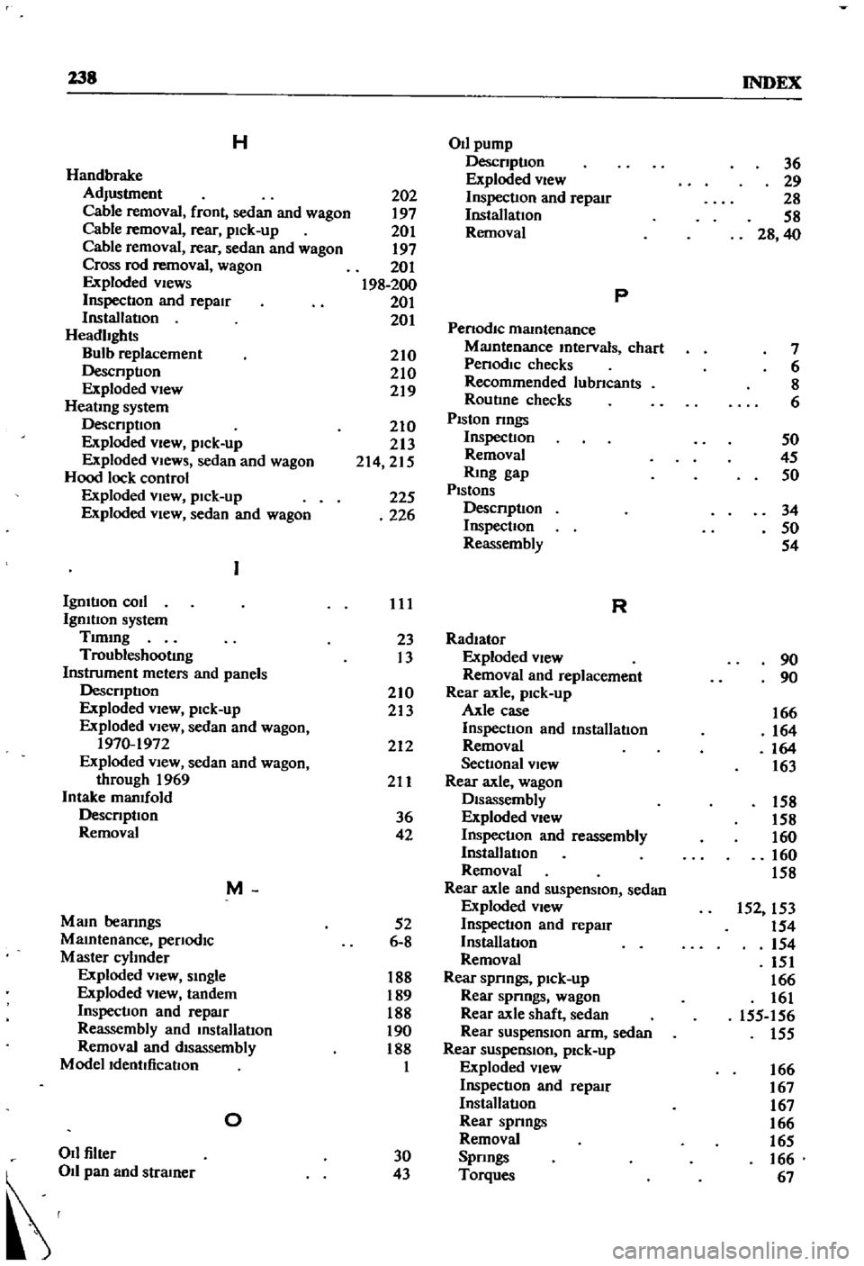
138
INDEX
H
OIl
pump
Descnptlon
36
Handbrake
Exploded
view
29
Adjustment
202
Inspection
and
repaIr
28
Cable
removal
front
sedan
and
wagon
197
Installation
58
Cable
removal
rear
pick
up
201
Removal
28
40
Cable
removal
rear
sedan
and
wagon
197
Cross
rod
removal
wagon
201
Exploded
views
198
200
p
Inspection
and
repair
201
Installation
201
Penodlc
mamtenance
Headlights
MaIntenance
mtervals
chart
7
Bulb
replacement
210
Penodlc
checks
6
Descnptlon
210
Recommended
lubncants
8
Exploded
view
219
Routine
checks
6
HeatIng
system
Piston
nngs
Descnptlon
210
Exploded
view
pick
up
213
Inspection
50
Exploded
VIews
sedan
and
wagon
214
215
Removal
45
Hood
lock
control
RIng
gap
50
Exploded
View
pick
up
225
Pistons
Descnptlon
34
Exploded
VIew
sedan
and
wagon
226
Inspection
50
Reassembly
54
Igmtlon
coil
111
R
Igmtlon
system
Tlmmg
23
Radiator
Troubleshooting
13
Exploded
view
90
Instrument
meters
and
panels
Removal
and
replacement
90
Descnptlon
210
Rear
axle
pick
up
Exploded
View
pick
up
213
Axle
case
166
Exploded
view
sedan
and
wagon
Inspection
and
mstalIatlon
164
1970
1972
212
Removal
164
Exploded
view
sedan
and
wagon
Sectional
view
163
through
1969
211
Rear
axle
wagon
Intake
manifold
Disassembly
158
Descnptlon
36
Exploded
view
158
Removal
42
Inspection
and
reassembly
160
InstallatIOn
160
Removal
158
M
Rear
axle
and
suspenSion
sedan
Exploded
view
152
153
Mam
beanngs
52
Inspection
and
repaIr
154
MaIntenance
penodlc
6
8
InstalIatlon
154
Master
cylInder
Removal
151
Exploded
vIew
smgle
188
Rear
spnngs
pick
up
166
Exploded
view
tandem
189
Rear
spnngs
wagon
161
Inspection
and
repllIr
188
Rear
axle
shaft
sedan
155
156
Reassembly
and
InstalIatlon
190
Rear
suspension
arm
sedan
155
Removal
and
disassembly
188
Rear
suspenSion
pick
up
Modelldentdicatlon
1
Exploded
view
166
Inspection
and
repllIr
167
InstalIatlon
167
0
Rear
spnngs
166
Removal
165
011
filler
30
Spnngs
166
d
43
Torques
67
Page 249 of 252
MAINTENANCE
LOG
DATE
TYPE
OF
SERVICE
COST
REMARKS
Page 251 of 252
j
h
duhl
book
lor
Jour
bike
I
r
r
r
t
lIIi
r
1J
COMBl
IlUIUOfIIOHl
0
1
2
I
K
NDA
1BMCf
lwaocll
so
OIft
I
i
I
J
I
A
Clymer
s
completely
new
professionally
written
motorcycle
servlcejman
I
uals
a
must
for
all
bike
ownersl
Expert
text
and
hundreds
of
photos
glve
i
model
by
model
serVice
repair
and
troubleshooting
Information
Jobs
for
I
the
amateur
are
fully
detailed
When
to
call
n
a
pro
IS
also
mad
e
c1eai
The
books
listed
below
offer
full
maintenance
information
for
rtI
re
than
200
separate
models
They
are
available
through
local
bo
kstores
motorcycle
dealers
automotive
accessories
outlets
or
postpaid
dU
3d
from
Clymer
Publications
I
I
BSA
TWINS
6SO
1963
1972
BULTACO
SINGLES
125
25Occ
All
Vear
HODAKA
SINGLES
90
lOCk
1964
1972
I
HONDA
SINGLES
SO
9O
1963
1971
HONDA
SINGLES
100
250cc
1970
1972
HONDA
TWINS
l125
350cc
1964
1972
HONDA
SCRAMlnERI
250
305cc
All
Year
HONDA
TWINSI4SO
1965
1973
HONDA
FOURShso
500
1972
HONDA
FOURS
7SO
19691972
HUSQVARNA
51
GLES
125
450cc
1966
1972
MJ02
5
SO
MJ03
7
SO
MJ07
6
SO
MJ10
S
SO
MJ15
5
SO
MJ20
S
SO
M330
4
SO
MJ33
5
SO
MJ32
5
SO
MJ41
5
50
M423
7
SO
KAWASAKI
SINGLES
90
350
1966
1972
KAWASAKI
TWINS
250
35O
c
1966
1971
KAWASAKI
TRIPLES
S50
7SO
1969
19n
MONTESA
125
360
1965
1972
OSSA
125
250
1971
1972
SUZUKI
SINGLES
50
UlCk
19U
1972
SUZUKI
TWINS
125
500cc
1964
1972
SUZUKI
TRIPLES
1971
1972
TRIUMPH
TWINS
500
6SO
1963
1971
YAMAHA
ROTARY
SINGLES
50
73
1963
1971
YAMAHA
ENDURO
SINGLES
90
360
1968
19n
YAMAHA
TWINS
9O
350cc
1965
1972
YAMAHA
TWINS
650
1970
1973
RIDE
AND
STAY
AlIVEu
The
complete
book
of
motorcycle
baSICS
defenSive
dmg
wet
weather
safety
tipS
signaling
efe
X910
2
95
M350
5
SO
MJ5
2
5
SO
M3531
5
SO
M356
7
SO
MJ62
7
50
M365
S
SO
M366
5
SO
MJ68
5
50
MJa2
5
SO
M3aa
4
50
M40a
4
50
MJ9a
4
SO
M403
5
SO
I
I
t
r
r
r
r
1
l
I
June
1973
publlcatlonY
@j
CLYMEIt
IONS
j
222
NORTH
VIRGIL
AVENUE
LOS
ANGELES
CALIF
90004
t
i