1968 DATSUN 510 height
[x] Cancel search: heightPage 9 of 252
4
CHAPTER
ONE
chassIs
number
Write
the
numbers
down
and
carry
them
ill
your
wallet
Service
Hints
Throughout
thIs
manual
keep
two
conven
bons
ill
mmd
Front
refers
to
the
front
of
the
vehicle
The
left
and
nght
sides
of
the
ve
hicle
refer
to
a
person
sittIng
ill
the
car
facing
forward
For
example
the
steenng
wheelIS
on
the
left
hand
Side
All
dimensIOns
and
capacities
are
expressed
ill
units
fanuhar
to
a
Umted
States
mechaniC
such
as
illches
and
pounds
Metric
measurements
are
also
given
Metnc
tools
are
reqUITed
to
work
on
the
Datsun
CD
DATSUN
IENGINE
CAPACITY
IMAX
HP
RPM
IWHEELBASE
IENGINE
NUMBER
FAR
NO
NlSSAN
MOTOR
co
LTD
YOKOHAMA
JAPAN
TYPEI
510
1595
cc
961P
6600
rpm
mm
L
1
00988
P61
l
O
1
l
M
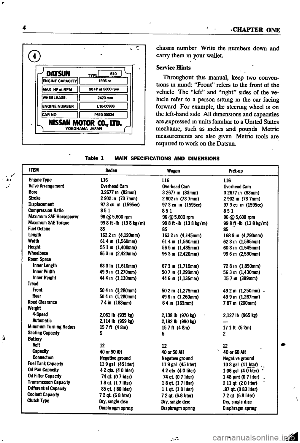
Table
1
MAIN
SPECIFICATIONS
AND
DIMENSIONS
r
ITEM
Sedan
Wagon
Plm
up
EnglDe
Type
L16
L16
L16
Valve
Arrangement
Overhead
Cam
Overhead
Cam
Overhead
Cam
Bore
3
26n
ID
83mm
3
2677
ID
83mm
3
2677
ID
83mm
Stroke
2902
ID
73
7mm
2
902
ID
73
7mm
2
902
In
73
7mm
Displacement
97
3
cu
ID
l595cc
97
3
cu
In
l595cc
97
3
cu
ID
1595cc
CompressIOn
Ratio
851
851
851
MaXimum
SAE
Hompower
96
@
5
600
rpm
96
@
5
600
rpm
96
@
5
600
rpm
MaXimum
SAE
Torque
998ft
Ib
138
kg
m
998ft
Ib
138
kg
m
9911
ft
Ib
138
kg
m
Fuel
Octane
85
85
85
Lengtb
1622
ID
4
12Omm
163
2
ID
4
I45mm
168
9
ID
4
290mm
Width
61
4
ID
l
560mm
61
4
ID
1
560mm
62
8
In
Cl
595mm
Height
55
lID
1
400mm
565
ID
Cl
435mm
60
8
ID
Cl
545mm
Wheelbase
95
3
ID
2
42Omm
95
3
ID
2
420mm
99
6
In
2
530mm
Room
Space
Inner
Length
63
3
In
1
61Omm
673
ID
1
710mm
72
8
ID
1
850mm
Inner
Width
499
ID
1
27Omm
507
ID
1
29Omm
563
In
1
430mm
Inner
Height
44
4
In
1
130mm
44
61D
1
135mm
15
7
ID
399mm
Tread
Front
50
4
ID
28Omm
502
In
1
275mm
492
In
1
250mm
Rear
504
In
1
280mm
496
In
Cl
260mm
499
ID
1
267mm
Road
Clearance
741n
l88mm
64
ID
l63mm
787
ID
200mm
Weight
4
Speed
2
0611b
935
kg
2
138
Ib
970
kg
2
127
Ib
965
kg
Automatic
2
114Ib
959
kg
2
182
Ib
990
kg
Minimum
Turning
RadiUS
157ft
48m
157ft
48m
171
ft
52m
Seating
Capaaty
5
5
2
Battery
Volt
12
12
12
Capacity
400rSOAH
400r50AH
40
or
60
AH
Connection
Negative
ground
Negative
ground
Negative
ground
Fuel
Tank
Capaaty
11
9
gal
45
liter
11
9
gal
45
liter
108
gal
41J
r
011
Pan
Capacity
42
qts
40
liter
4
2
qb
40
liter
1
06
gal
40
Iller
011
Filter
Capaaty
74
ql
07
liter
74
ql
0
7
liter
1
48
Pint
0
7
liter
Transmission
Capaaty
1
8
ql
1
7
liter
18
ql
1
7
Iller
2
11
qt
20
Iller
Dlflerenbal
Capaaty
85
ql
80
liter
11
ql
1
0
liter
87
ql
0
83
lIter
Coolant
Capaaty
7
2
ql
6
8
liter
7
2
ql
6
8
lIter
7
2
qt
6
8
Iller
Clutch
Type
Dry
Single
diSC
Dry
slDgle
diSC
Dry
slDgle
diSC
Draphragm
spnng
Diaphragm
spnng
Diaphragm
spnng
l
Page 65 of 252
60
SIX
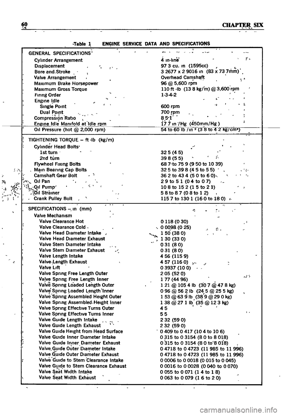
Table
1
ENGINE
SERVICE
DATA
AND
SPECIFICATIONS
GENERAL
SPECIFICATIONS
Cylinder
Arrangement
DIsplacement
Bore
and
Stroke
Valve
Arrangement
MaxImum
Brake
Horsepower
MaxImum
Gross
Torque
Firing
Order
Engme
dle
Smgle
POint
Dual
Pomt
CompressIon
RatIo
Engme
Idle
Mamfold
at
Idle
rpm
011
Pressure
hot
@
2
000
rpm
i
TIGHTENING
TORQUE
ft
Ib
kg
m
Cylinder
Head
Bolts
1st
turn
2nd
turn
Flywheel
Flxmg
Bolts
M
In
Beanng
Cap
Bolts
Camshaft
Gear
Bolt
I
011
Pan
1
1
fF
I
011
Pump
QII
Stramer
F
I
Crank
Pulley
Bolt
SPECIFICATIONS
In
mm
Valve
Mechamsm
Valve
Clearance
Hot
Valve
Clearance
Cold
Valve
Head
DIameter
Intake
Valve
Head
DIameter
Exhaust
Valve
Stem
DIameter
Intake
Valve
Stem
DIameter
Exhaust
Valve
Length
Intake
Valve
Length
Exhaust
Valve
LIft
Valve
Spring
Free
Length
Outer
Valve
Sprmg
Free
Length
Inner
Vaiv
Spnng
Loaded
Length
Outer
Valve
Spring
Loaded
Length
Inner
Valve
Sprmg
Assembllld
HeIght
Outer
Valve
Spnng
Assembled
Helght
Inner
Valve
Spnng
Effective
Turns
Outer
Valve
Sprmg
EffectIve
Turns
Inner
Valve
GUIde
Length
Intake
Valve
GUIde
Length
Exhaust
Valve
GUIde
HeIght
from
Head
Surface
Valve
GUIde
Inner
DIameter
Intake
Valve
GUIde
Inner
DIameter
Exhaust
Va
Ive
GUIde
Outer
Dlam
eter
Intake
Valve
GUIde
Outer
DIameter
Exhaust
Valve
GUIde
to
Stem
Clearance
Intake
Valve
GUIde
to
Stem
Clearance
Exhaust
Valve
eat
W
dth
Intake
Valve
SEtat
WIdth
Exhaust
4
m
Ilnil
97
3
cu
m
1595cc
3
2677
x
2
9016
In
83
x
73
7mm
Overhead
Camshaft
96
@
5
600
rpm
110
ft
Ib
13
8
kg
m
@
3
600
rpm
1
3
4
2
r
600
rpm
700
pm
85
1
i7
7
In
Hg
450mm
Hg
54
to
60
Ib
m
2
3
8
tQ
4
2
Iig
cm
325
4
5
39
8
5
5
68
No
75
9
9
50
to
1039
325
to
39
8
4
5
to
5
5
362
to
43
4
50
to
60
2
9
to
5
1
0
4
to
0
7
108
to
15
2
1
5
to
2
1
58t087
08to
12
1157
to
130
1
160
to
180
o
118
0
30
o
0C
98
0
25
1
50
38
0
1
30
33
0
031
80
031
80
456
1159
4
57
116
O
03937
100
2
05
52
0
1
77
44
96
1
21
@
1054
Ib
3
07
@
47
8
kg
o
96
@
56
Ib
24
5
@
25
5
kg
1
53
@
63
9
Ib
38
9
@
29
0
kg
1
38
@
27
1
Ib
35
@
123
kg
45
I
55
2
32
59
0
2
32
59
0
0409
to
0
417
104
to
106
0315
to
03154
80
to
8018
0315
to
03154
80
to
8
Oi8
04718
to
04723
11
985
to
11
996
04718
to
04723
11
985
to
11
996
00006
to
00018
0
015
to
0
045
00016
to
00028
0040
to
0070
o
055
to
0
071
1
4
to
1
8
0063
to
0079
1
6
to
20
Page 66 of 252
ENGINE
61
SPECIFICATIONS
In
mm
continued
Valve
Seat
Interference
Fit
Intake
Valve
Seat
Interference
Flt
Exh
ust
Valve
GUide
Interference
fit
I
Camshaft
and
Timing
Chain
Ca
mshaft
End
Play
Camshaft
Lobe
LIft
Camshaft
Journal
Diameter
Camshaft
Bend
Camshaft
Bearing
Inner
Diameter
Camshaft
Journal
to
B
arlng
Clearance
Rocker
Arm
Lever
Ratio
Connecting
Rod
Center
Distance
Standard
Bearing
Thickness
Big
End
Play
Connectmg
Rod
Beanng
Clearance
Connecting
Rod
Bend
per
3
937
In
100mm
Crankshaft
and
Main
Beanng
Journal
Diameter
Journal
Taper
and
Out
ot
Round
Crankshaft
Free
End
Play
Crank
Pin
Diameter
Crank
Pin
Taper
and
Out
ot
Round
Main
Bearing
Thickness
Main
Beanng
Clearance
Crankshaft
Bend
Piston
Standard
Diameter
Ellipse
Difference
Ring
Groove
Top
Second
011
Piston
to
Bore
Clearance
Piston
Pm
Hole
Offset
Piston
Pin
Piston
Pin
Diameter
Piston
Pin
Length
Piston
Pin
to
Piston
Clearance
Interference
Fit
ot
Piston
Pin
to
Connecting
Rod
Bushing
Piston
Ring
Ring
Height
Top
Second
011
Side
Clearance
Top
Second
011
Ring
Gap
Top
Second
011
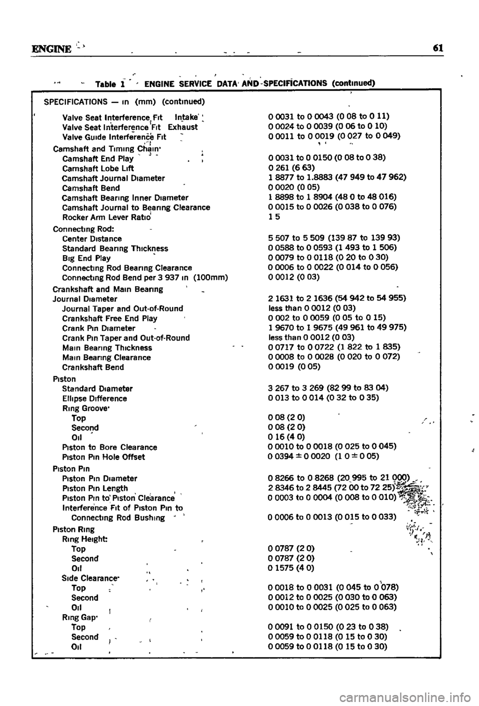
Table
1
ENGINE
SERVICE
DATA
AND
SPECIFicATIONS
continued
00031
to
0
0043
0
OB
to
0
11
00024
to
0
0039
006
to
0
10
00011
to
00019
0027
to
0049
00031
to
0
0150
0
08
to
0
38
o
261
6
63
18877
to
1
8883
47
949
to
47
962
o
0020
0
05
1
8898
to
1
8904
48
0
to
48
016
00015
to
0
0026
0038
to
0
076
15
5
507
to
5
509
139
87
to
139
93
o
0588
to
0
0593
1
493
to
1
506
00079
to
0
0118
0
20
to
030
o
0006
to
0
0022
0
014
to
0
056
o
0012
003
2
1631
to
2
1636
54
942
to
54
955
less
than
00012
003
o
002
to
0
0059
0
05
to
0
15
1
9670
to
1
9675
49961
to
49
975
less
than
0
0012
0
03
o
0717
to
0
0722
1
822
to
1
835
o
0008
to
0
0028
0
020
to
0
072
00019
005
3267
to
3
269
8299
to
83
04
0013
to
0014
032
to
035
008
20
o
08
2
0
o
16
4
0
00010
to
0
0018
0
025
to
0
045
00394
0
0020
1
O
0
05
o
8266
to
0
8268
20
995
to
21
0
0
2
8346
to
2
8445
72
00
to
72
251
o
0003
to
0
0004
0
OOS
to
0
OlD
00006
to
0
0013
0015
to
0
033
o
0787
2
0
o
0787
2
0
o
1575
40
00018
to
00031
0
045
to
0
078
00012
to
0
0025
0030
to
0
063
00010
to
00025
0025
to
0
063
i
J
I
n
T
00091
to
0
0150
023
to
038
00059
to
0
0118
0
15
to
0
30
00059
to
0
0118
0
15
to
0
30
Page 109 of 252
104
CHAPTER
NINE
2
When
one
sIde
shows
low
resIstance
and
the
other
shows
high
resIstance
the
dIode
IS
satls
factory
If
both
sIdes
are
low
there
IS
a
short
CIrCUIt
If
both
sIdes
are
hIgh
there
IS
an
open
CIrcUIt
All
diodes
With
open
or
short
ClrC
ts
must
be
replaced
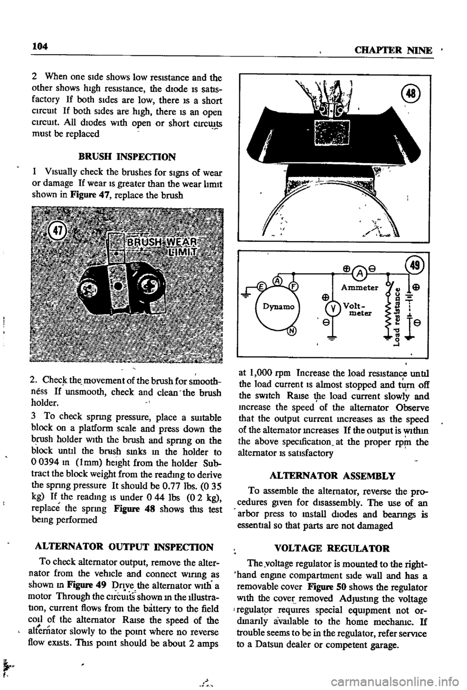
BRUSH
INSPECTION
1
VIsually
check
the
brushes
for
SIgnS
of
wear
or
damage
If
wear
IS
greater
than
the
wear
lIrmt
shown
in
Figure
47
replace
the
brush
2
ChecJ
the
movement
of
the
brush
for
smooth
ness
If
unsmooth
check
and
clean
the
brush
holder
3
To
check
spnng
pressure
place
a
SUItable
block
on
a
platform
scale
and
press
down
the
brush
holder
WIth
the
brush
and
spnng
on
the
block
untIl
the
brush
smks
In
the
holder
to
00394
m
lmm
heIght
from
the
holder
Sub
tract
the
block
weight
from
the
reading
to
derive
the
spnng
pressure
It
should
be
0
77
Ibs
035
kg
If
the
readmg
IS
under
0
44
Ibs
0
2
kg
replace
the
spring
Figure
48
shows
thIS
test
being
performed
ALTERNATOR
OUTPUT
INSPECTION
To
check
alternator
output
remove
the
alter
nator
from
the
vehIcle
and
connect
wumg
as
shown
m
Figure
49
Dq
ve
the
alternator
WIth
a
motor
Through
the
CIrcUItS
shown
m
the
Illustra
tIon
current
flows
from
the
battery
to
the
field
coll
of
the
alternator
RaISe
the
speed
of
the
alternator
slowly
to
the
pOInt
where
no
reverse
flow
eXISts
ThIs
pOInt
should
be
about
2
amps
I
at
1
000
rpm
Increase
the
load
reSIStance
untIl
the
load
current
IS
almost
stopped
and
tlI
rn
off
the
SWItch
RaIse
the
load
current
slowly
and
mcrease
the
speed
of
the
alternator
Observe
that
the
output
current
mcreases
as
the
speed
of
the
alternator
mcreases
If
the
output
is
wlthm
the
above
specmcatIon
at
the
proper
rp
ll
the
alternator
IS
satIsfactory
ALTERNATOR
ASSEMBLY
To
assemble
the
alternator
reverse
the
pro
cedures
given
for
dIsassembly
The
use
of
an
arbor
press
to
mstall
dIodes
and
bearmgs
is
essentIal
so
that
parts
are
not
damaged
VOLTAGE
REGULATOR
The
voltage
regulator
is
mounted
to
the
right
hand
engme
compartment
SIde
wall
and
has
a
removable
cover
Figure
SO
shows
the
regulator
With
the
cover
removed
AdjustIng
the
voltage
regulatpr
reqUIres
special
eqUIpment
not
or
dmanly
avallable
to
the
home
mechanlc
If
trouble
seems
to
be
in
the
regulator
refer
servIce
to
a
Datsun
dealer
or
competent
garage
Page 133 of 252
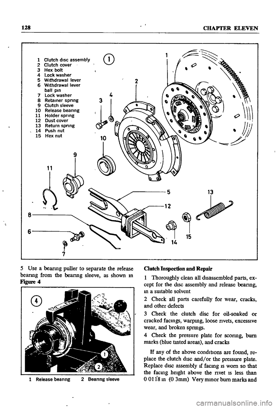
128
CHAPTER
ELEVEN
1
Clutch
disc
assembly
2
Clutch
cover
3
Hex
bolt
4
Lock
washer
5
Withdrawal
lever
6
Withdrawal
lever
ball
pin
7
Lock
washer
8
Retainer
spnng
9
Clutch
sleeve
10
Release
bearing
11
Holder
spring
12
Dust
cover
13
Return
spring
14
Push
nut
15
Hex
nut
CD
9
11
8
6
7
1
Release
beanng
2
Beanng
sleeve
2
5
13
12
15
14
Clutch
Inspection
and
Repair
1
Thoroughly
clean
all
dISassembled
parts
ex
cept
for
the
dISc
assembly
and
release
bearmg
In
a
SUItable
solvent
2
Check
all
parts
carefully
for
wear
cracks
and
other
defects
3
Check
the
clutch
disc
for
oil
soaked
or
cracked
faCIngs
warpmg
loose
nvets
exceSSIve
wear
and
broken
spnngs
4
Check
the
pressure
plate
for
sconng
bum
marks
blue
tlnted
areas
and
cracks
If
any
of
the
above
condItIons
are
found
re
place
the
clutch
dISC
and
or
the
pressure
plate
Replace
dISC
assembly
1f
facmg
IS
worn
so
that
the
facmg
heIght
above
the
nvet
IS
less
than
00118m
03mm
Very
mmor
bum
marks
and
Page 134 of 252
CLUTCH
TRANSMISSION
AND
DRIVESHAFI
129
scratches
on
the
pressure
plate
may
be
removed
with
crocus
cloth
If
the
source
of
clutch
trouble
IS
still
not
evl
dent
take
the
pressure
plate
and
disc
to
a
compe
tent
garage
to
check
the
pressure
plate
finger
release
height
and
nmout
Never
attempt
to
ad
just
the
fingers
or
dismantle
the
pressure
plate
Without
proper
tools
and
experience
Check
the
release
bearing
by
holdmg
the
Inner
race
and
rotatmg
the
outer
race
With
hght
pres
sure
applied
If
the
bearing
is
rough
or
noisy
replace
it
CAUTION
Never
clean
the
release
bearing
In
solvent
It
IS
prelubriCflted
at
the
fac
tory
Simply
wipe
with
a
Unt
free
cloth
If
the
release
bearing
shows
any
signs
of
loss
of
lubncant
install
a
new
bearing
Replace
the
sleev
lu
SignS
of
wear
are
evident
Clutch
Reassembly
1
Be
sure
your
hands
are
clean
for
the
initIal
assembly
2
Inspect
the
clutch
facings
pressure
plate
and
flywheel
to
be
sure
they
are
free
from
grease
oil
and
other
foreIgn
material
3
TIghtly
fit
release
bearmg
onto
the
bearing
sleeve
When
beanng
IS
mstalled
turn
bearmg
With
a
finger
to
make
sure
It
operates
smoothly
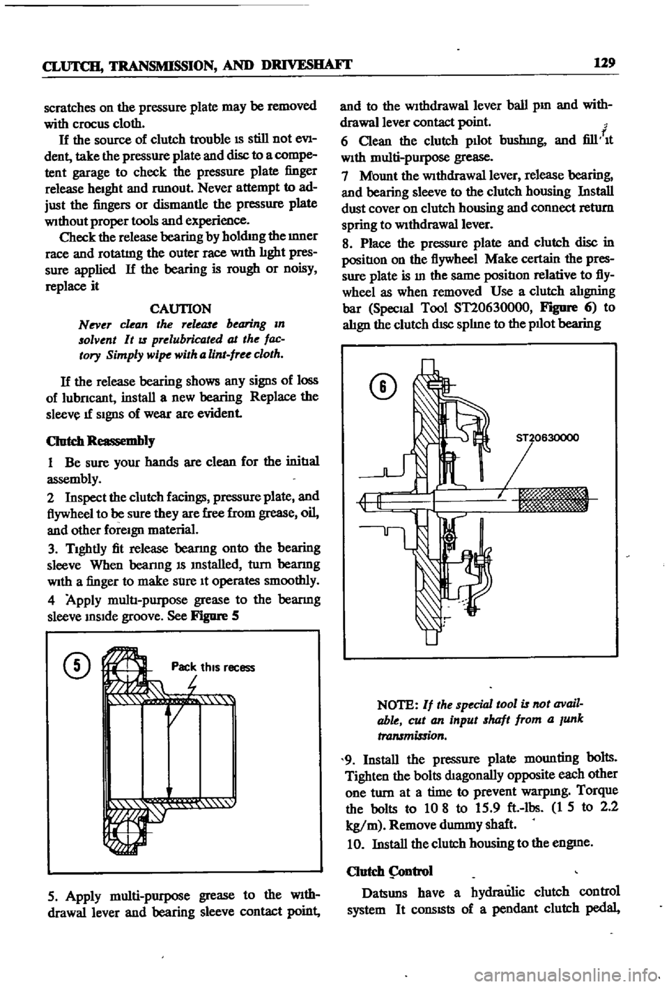
4
Apply
multI
purpose
grease
to
the
bearmg
sleeve
InSIde
groove
See
Figure
5
CD
Ji
rot
Pac
thiS
r
r
r
1
1i
QI
ecess
5
Apply
multi
purpose
grease
to
the
WIth
drawallever
and
bearing
sleeve
contact
point
and
to
the
Withdrawal
lever
ball
pm
and
with
drawallever
contact
point
f
6
Clean
the
clutch
pllot
bushmg
and
fill
It
With
multi
purpose
grease
7
Mount
the
WithdraWal
lever
release
bearing
and
bearing
sleeve
to
the
clutch
housing
Install
dust
cover
on
clutch
housing
and
connect
return
spring
to
WithdraWal
lever
8
Place
the
pressure
plate
and
clutch
disc
in
positIon
on
the
flywheel
Make
certain
the
pres
sure
plate
is
In
the
same
positIon
relative
to
fly
wheel
as
when
removed
Use
a
clutch
alIgning
bar
Special
Tool
ST20630000
FIgDfe
6
to
alIgn
the
clutch
dISc
splIne
to
the
pllot
bearing
CD
NOTE
If
the
special
tool
is
not
avail
able
cut
an
input
shaft
from
a
Junk
transmission
9
Install
the
pressure
plate
mounting
bolts
Tighten
the
bolts
dIagonally
opposite
each
other
one
turn
at
a
time
to
prevent
warpmg
Torque
the
bolts
to
10
8
to
15
9
ft
lbs
1
5
to
2
2
kg
m
Remove
durmny
shaft
10
Install
the
clutch
housing
to
the
engme
Clutch
ntrol
Datsuns
have
a
hydraulic
clutch
control
system
It
consISts
of
a
pendant
clutch
pedal
Page 135 of 252
130
CHAPTER
ELEVEN
master
cylInder
operatlng
cylinder
and
with
drawal
lever
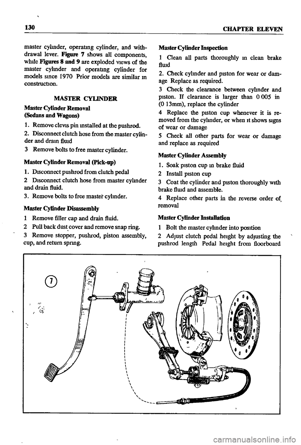
Figure
7
shows
all
components
whlle
Figures
8
and
9
are
exploded
VIews
of
the
master
cylmder
and
operatIng
cylinder
for
models
smce
1970
Prior
models
are
similar
In
construction
MASTER
CYLINDER
Master
Cylinder
Removal
Sedans
and
Wagons
1
Remove
cleVIS
pin
mstalled
at
the
pushrod
2
Disconnect
clutch
hose
from
the
master
cylin
der
and
dram
flwd
3
Remove
bolts
to
free
master
cylinder
Master
Cylinder
Removal
Pick
up
1
DIsconnect
pushrod
from
clutch
pedal
2
DIsconnect
clutch
hose
from
master
cylInder
and
drain
fluid
3
Remove
bolts
to
free
master
cylInder
Master
Cylinder
Disassembly
1
Remove
filler
cap
and
drain
fluid
2
Pull
back
dust
cover
and
remove
snap
ring
3
Remove
stopper
pushrod
piston
assembly
cup
and
return
spnng
CD
i
Master
Cylinder
Inspection
1
Clean
all
parts
thoroughly
In
clean
brake
flwd
2
Check
cylInder
and
pISton
for
wear
or
dam
age
Replace
as
required
3
Check
the
clearance
between
cylInder
and
pIston
If
clearance
is
larger
than
0
005
in
0
13mm
replace
the
cylinder
4
Replace
the
pISton
cup
whenever
it
is
re
moved
from
the
cylInder
or
when
It
shows
SIgnS
of
wear
or
damage
5
Check
all
other
parts
for
wear
or
damage
and
replace
as
required
Master
Cylinder
Assembly
1
Soak
piston
cup
m
brake
fluid
2
Install
pIston
cup
3
Coat
the
cylinder
and
pIston
thoroughly
WIth
brake
flwd
and
assemble
4
Replace
other
parts
in
the
reverse
order
of
removal
Master
Cylinder
Installation
1
Bolt
the
master
cylInder
into
pOSItion
2
Adjust
clutch
pedal
heIght
by
adjusting
the
pushrod
length
Pedal
heIght
from
floorboard
Page 137 of 252
132
CHAPTER
ELEVEN
CD
NAnCO
22
20
21
r
i
T
l
C
r
Jl
i
i
18
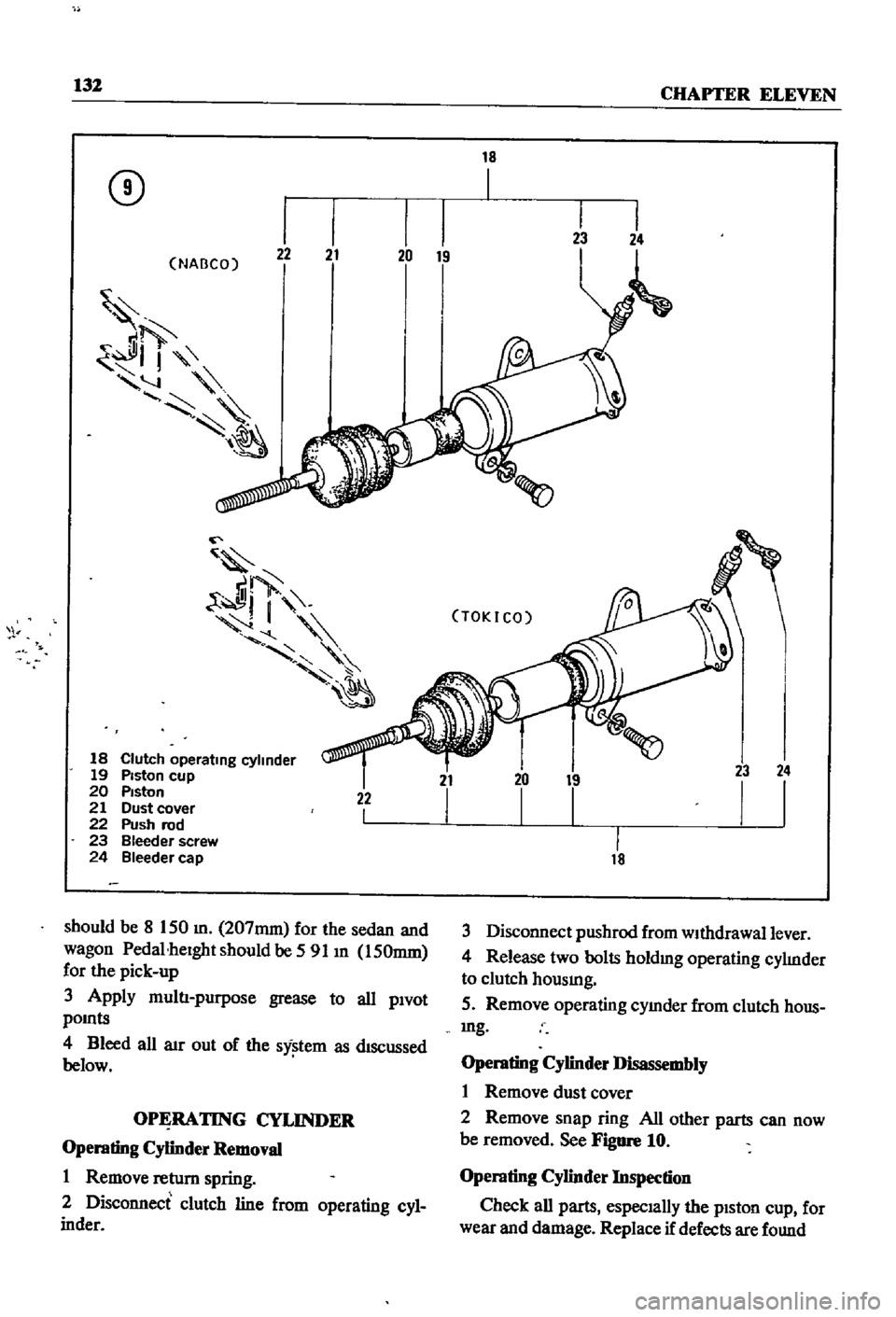
Clutch
operating
cylinder
19
Piston
cup
20
PIston
21
Dust
cover
22
Push
rod
23
Bleeder
screw
24
Bleeder
cap
22
I
should
be
8
150
m
207mm
for
the
sedan
and
wagon
Pedal
heIght
should
be
591
m
150mm
for
the
pick
up
3
Apply
multI
purpose
grease
to
all
PIvot
pOInts
4
Bleed
all
aIr
out
of
the
sy
tem
as
dIscussed
below
OPERATING
CYLINDER
Operating
CyHnder
Removal
1
Remove
retum
spring
2
Disconnect
clutch
line
from
operating
cyl
inder
18
Ii
TOKICO
21
I
LL
18
23
24
I
I
3
Disconnect
pushrod
from
wIthdrawal
lever
4
Release
two
bolts
holdmg
operating
cylInder
to
clutch
hOUSIng
5
Remove
operating
cymder
from
clutch
hous
mg
Operating
CyHnder
Disassembly
1
Remove
dust
cover
2
Remove
snap
ring
All
other
parts
can
now
be
removed
See
Figure
10
Operating
CyHnder
Inspection
Check
all
parts
especIally
the
pIston
cup
for
wear
and
damage
Replace
if
defects
are
found