1968 DATSUN 510 stop start
[x] Cancel search: stop startPage 18 of 252

TROUBLESHOOTING
13
trouble
may
also
be
worn
bearings
Remove
the
alternator
and
repair
ENGINE
These
procedures
assume
the
starter
cranks
the
engme
over
normally
If
not
refer
to
Starter
section
m
this
chapter
1
Engme
won
t
start
Could
be
caused
by
the
IgOltlon
or
fuel
problems
First
determine
If
high
voltage
to
spark
plug
occurs
To
do
thiS
dISconnect
one
of
the
spark
plug
wires
Hold
the
exposed
wrre
termlOal
y
to
Y2
lOch
from
ground
any
metal
in
engine
com
partment
With
an
msulated
screwdriver
Crank
the
engme
over
If
sparks
do
not
Jump
to
ground
or
the
sparks
are
very
weak
the
trouble
may
be
10
the
IgnitIOn
system
See
Ignition
System
Trou
bleshootmg
to
further
check
If
sparks
occur
properly
the
trouble
may
be
10
the
fuel
system
See
Fuel
System
Troubleshootmg
2
Engme
misses
steadily
Remove
one
spark
plug
wrre
at
a
tune
and
ground
the
wrre
If
engme
mISs
increases
that
cyhnder
was
work
109
properly
Reconnect
the
wire
and
check
the
others
When
a
wire
IS
dIs
connected
and
engme
miss
remams
the
same
that
cylinder
IS
not
finng
Check
spark
as
descnbed
10
Step
1
If
no
spark
occurs
for
one
cyhnder
only
check
dlStnbutor
cap
wrre
and
spark
plug
If
spark
occurs
prop
erly
check
compressIOn
and
mtake
maOlfold
vacuum
to
ISolate
the
trouble
3
Engme
misses
erratlcally
at
all
speeds
Interrmttent
trouble
can
be
difficult
to
find
It
could
be
ill
the
Ignition
system
exhaust
system
or
fuel
system
Follow
troubleshooting
proce
dures
for
these
systems
carefully
to
isolate
the
trouble
4
Engme
misses
at
Idle
only
Trouble
could
exist
anywhere
ill
IgOltlon
system
Follow
Ignition
TroubleshootlOg
procedure
care
fully
Trouble
could
also
eXist
10
the
carburetor
Idle
crrcult
Check
Idle
mIXture
adjustment
and
check
for
restnctions
m
the
idle
crrcUlt
5
Engme
misses
at
high
speed
only
Problems
could
be
ill
the
fuel
or
IgOltlon
systems
heck
accelerator
pump
operation
fuel
pump
dehvery
fuel
hnes
etc
as
descnbed
under
Fuel
System
Troubleshootillg
Also
check
spark
plugs
and
wrres
6
Low
performance
at
all
speeds
poor
acceleratIOn
Trouble
usually
ill
IgOltlon
or
fuel
system
Check
each
With
the
appropnate
troubleshooting
pro
cedure
7
ExceSSive
fuel
consumptIOn
Could
be
caused
by
a
Wide
variety
of
seemmgly
unrelated
factors
Check
for
clutch
shppage
brake
drag
defective
wheel
beanngs
or
poor
front
end
alignment
Check
IgOltlOn
system
and
fuel
system
8
011
pressure
lamp
does
not
light
when
IgmtlOn
switch
IS
on
Check
the
alternator
warning
lamp
If
it
ISn
t
on
either
go
to
Step
1
Chargmg
System
Trouble
shootlOg
If
only
the
oil
pressure
lamp
IS
off
open
the
englOe
compartment
hd
and
locate
the
oil
pressure
sender
on
the
block
near
the
oil
filter
Make
sure
the
wrre
is
connected
to
the
sender
and
makmg
good
contact
Pull
the
wrre
off
and
ground
it
If
the
lamp
hghts
replace
the
sender
If
the
lamp
does
not
light
replace
the
lamp
9
011
pressure
lamp
lights
or
flickers
when
engme
IS
runmng
Indicates
low
or
complete
loss
of
oil
pressure
Stop
the
englOe
unmedmtely
coast
to
a
stop
With
the
clutch
dISengaged
Tlus
may
simply
be
caused
by
a
low
oil
level
or
an
overheatmg
en
glOe
Check
the
oil
level
and
fan
belt
tensIOn
Check
for
a
shorted
oil
pressure
sender
with
an
ohmmeter
or
a
contlOulty
tester
Remove
and
clean
the
oil
dipstick
and
check
oil
level
and
condition
RepleOlsh
or
replace
the
oil
as
re
qurred
Listen
for
unusual
nOISes
mdlcatmg
dam
aged
beanngs
etc
Do
not
re
start
the
engine
until
you
know
why
the
hght
went
on
and
are
sure
that
the
problem
has
been
corrected
IGNITION
SYSTEM
This
procedure
assumes
the
battery
IS
ill
good
enough
condition
to
crank
the
engme
at
a
normal
rate
Page 29 of 252

P
r
OVll
t
ate
I
l
h
l
JlA
ye
I
o
ctg
fI
O
0
I
d
1e
d
c
Ji
uo
JJ
cb
c
s
rlr
I
l
4
c
1
2
24
CHAPTER
FOUR
block
and
should
be
used
as
the
reference
point
m
II
1akmg
adjustments
6
With
a
piece
of
white
chalk
mark
a
hne
down
the
center
of
the
pomter
and
mark
the
timing
groove
on
the
crankshaft
pulley
which
IS
to
be
used
m
tImmg
the
engine
SpecIficatIon
for
tun
ing
reqUIres
trlhmg
at
10
degrees
before
top
dead
center
wluch
would
be
the
fourth
mark
from
the
left
end
of
the
row
of
marks
7
Loosen
the
hold
down
bolt
at
the
base
of
the
dlstnbutor
8
Locate
the
slow
speed
1
Ile
adjustIng
screw
on
the
carburetor
so
that
Ile
speed
can
be
adjusted
whIle
runnmg
Also
locate
throttle
adJustmg
screw
9
Start
engme
and
adjust
speed
With
the
adJust
ing
screws
to
the
readmgs
below
Smgle
pomt
dIStributor
600
rpm
Dual
pomt
trlbutor
700
rpm
10
Alternate
adjustment
of
the
two
screws
untIl
the
smoothest
Idle
at
the
proper
speed
IS
achieved
11
Pomt
the
tlIrung
lIght
at
the
stationary
pomter
When
the
lIght
flashes
the
timmg
mark
n
the
crankshaft
pulley
should
hne
up
With
the
mark
on
the
stationary
pomter
If
It
does
not
exactly
Ime
up
rotate
the
dlstnbutor
gradually
untIl
the
marks
align
mdlcatlng
correct
timmg
12
Shut
off
the
engme
remove
the
tmung
lIght
and
tachometer
tighten
the
hold
down
bolt
on
the
dlStnbutor
and
connect
the
vacuum
advance
hne
to
the
tli
tnbutor
IGNITION
TIMING
IDLE
SPEED
IDLE
MIXTURE
DUAL
POINT
DISTRIBUTOR
ONLY
The
followmg
applies
to
velucles
With
dual
pomt
distributor
and
an
exhaust
emission
con
trol
deVice
If
these
procedures
are
followed
ha
ul
exhaust
emisSion
should
be
below
the
maximum
allowable
level
1
Locate
the
Idle
and
throttle
adJustmg
screws
on
the
carburetor
2
Warm
up
the
engine
thoroughly
3
Connect
tachometer
and
tmung
light
4
Set
the
Id
le
speed
at
700
rpm
With
the
Idle
adjust
screw
5
Adjust
IgnltJ
on
tuning
at
10
degrees
before
top
dead
center
6
Increase
the
speed
of
the
engme
to
2
000
rpm
With
the
accelerator
or
throttle
hnkage
and
hold
for
about
15
seconds
7
Return
to
Idle
for
one
mmute
8
Set
the
engme
to
best
Idle
at
750
rpm
770
rpm
for
automatJ
c
transIDlsslOn
With
the
Idle
and
throttle
adJustmg
screws
9
Re
uce
engme
speed
at
700
rpm
720
rpm
for
automatic
transmission
by
turnmg
the
Idle
adJustmg
screw
clockWise
for
a
leaner
IlliXture
10
Connect
a
wife
lead
between
the
advance
ami
retard
Side
tenrunals
See
Figure
4
Speed
should
drop
from
100
to
150
rpm
11
Check
IgIl1tIon
tmung
With
tImmg
light
It
should
now
be
at
top
d
ad
center
12
If
the
tlmmg
IS
nSJt
correct
stop
the
engme
and
adjust
the
retarded
breaker
pomt
13
Start
the
engme
and
reclieck
ili
tmung
If
l
incorrect
reset
the
retarded
breaker
pomt
until
it
IS
correct
Repeat
s
nece
s
14
Disconnect
the
wife
bet
reen
the
advance
and
retard
termmals
15
Recheck
tmung
It
should
be
10
degrees
before
top
dead
center
16
If
mcorrect
repeat
the
above
procedures
un
tIl
satIsfactory
17
T
he
Idle
speed
of
automatic
transnllsslOn
vehicles
should
be
about
575
rpm
With
the
gear
j
selector
m
the
dhve
poSltlon
c
t
DWELL
ANGLE
SETIING
1
Connect
the
dwell
angle
meter
2
PLoJust
dwell
angle
to
49
to
55
degrees
OMPRESSION
TEST
I
A
compressIOn
test
IS
performed
to
check
for
worn
piston
nngs
or
to
detect
the
cause
of
a
low
speed
miss
Before
undertaking
the
test
el
llmate
the
pOSSibility
of
sticky
valves
by
usmg
one
of
the
oil
additives
deSigned
for
the
purpose
With
valves
free
test
compressIOn
as
follows
1
Run
the
engme
for
15
to
20
mmutes
untIl
normal
operating
temperatures
are
obtained
2
Shut
off
engme
remove
arr
cleaner
and
Page 74 of 252
FUEL
SYSTEM
69
CARBURETOR
The
carburetor
IS
an
Hltach1
Type
DAF328
Several
varIations
are
used
dependmg
on
the
model
year
type
of
transmissIOn
and
the
emIS
SIon
control
system
The
dIfferent
models
are
the
same
as
far
as
basiC
operation
IS
concerned
Therefore
the
followmg
dISCUSSIon
covers
a
typIcal
carburetor
The
automatIc
choke
IS
used
on
automatIc
transmISSIon
and
1972
models
only
All
other
chokes
are
manual
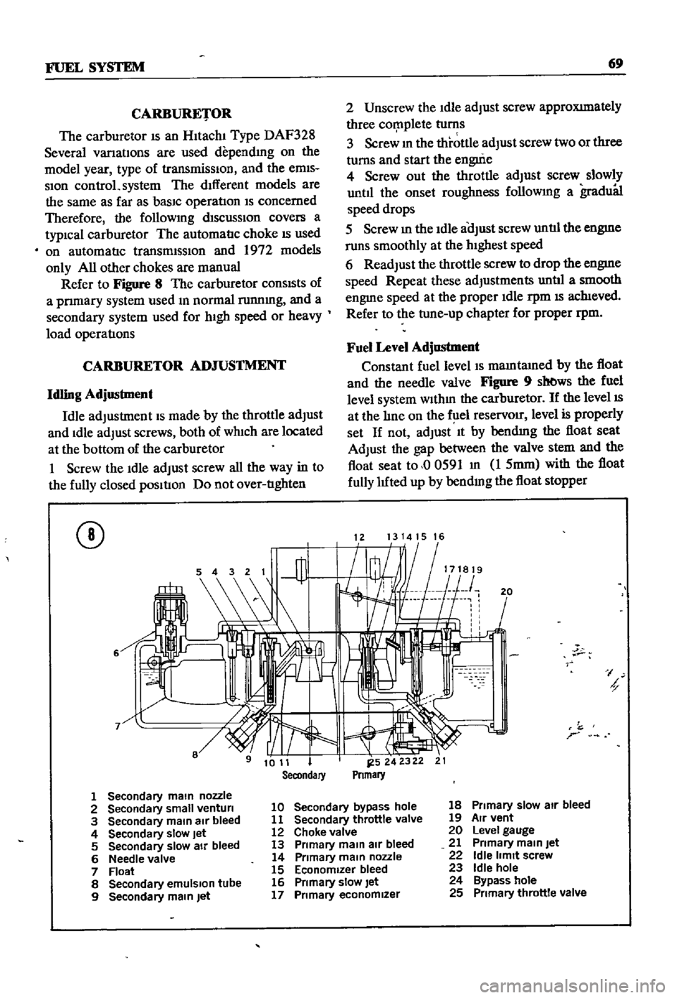
Refer
to
Figure
8
The
carburetor
conSIsts
of
a
pnmary
system
used
m
normal
runnmg
and
a
secondary
system
used
for
hIgh
speed
or
heavy
load
operatIons
CARBURETOR
ADJUSTMENT
Idling
Adjustment
Idle
adjustment
IS
made
by
the
throttle
adjust
and
Idle
adjust
screws
both
of
wh1ch
are
located
at
the
bottom
of
the
carburetor
1
Screw
the
Idle
adjust
screw
all
the
way
in
to
the
fully
closed
pOSItIon
Do
not
over
tIghten
CD
6
2
Unscrew
the
Idle
adjust
screw
approXImately
three
cor
nplete
turns
3
Screw
m
the
throttle
adjust
screw
two
or
three
turns
and
start
the
engui
e
4
Screw
out
the
throttle
adjust
screw
slowly
until
the
onset
roughness
followmg
a
gradu81
speed
drops
5
Screw
m
the
Idle
aOJust
screw
untIl
the
engme
runs
smoothly
at
the
hIghest
speed
6
Readjust
the
throttle
screw
to
drop
the
engme
speed
Repeat
these
adjustments
untIl
a
smooth
engme
speed
at
the
proper
Idle
rpm
IS
ach1eved
Refer
to
the
tune
up
chapter
for
proper
rpm
Fuel
Level
Adjustment
Constant
fuel
level
IS
mamtamed
by
the
float
and
the
needle
valve
Figure
9
sb
ws
the
fuel
level
system
wlthm
the
carburetor
If
the
level
IS
at
the
lIne
on
the
f
lel
reservOir
level
is
properly
set
If
not
adjust
It
by
bendmg
the
float
seat
Adjust
the
gap
between
the
valve
stem
and
the
float
seat
to
00591
m
1
5mm
with
the
float
fully
luted
up
by
bendmg
the
float
stopper
1213141516
20
I
h
r
1
Secondary
main
nozzle
2
Secondary
small
venturi
10
Secondary
bypass
hole
18
Primary
slow
air
bleed
3
Secondary
main
air
bleed
11
Secondary
throttle
valve
19
Air
vent
4
Secondary
slow
Jet
12
Choke
valve
20
Level
gauge
5
Secondary
slow
air
bleed
13
Primary
main
air
bleed
21
Primary
main
Jet
6
Needle
valve
14
Primary
main
nozzle
22
Idle
limit
screw
7
Float
15
Economizer
bleed
23
Idle
hole
8
Secondary
emulSion
tube
16
Primary
slow
let
24
Bypass
hole
9
Secondary
main
Jet
17
Primary
economizer
25
Primary
throttle
valve
Page 75 of 252
70
CHAPTER
SEVEN
CD
1
Float
seat
2
Roat
3
Roat
stopper
4
Needle
valve
Starting
Interlock
Valve
Opening
Adjustment
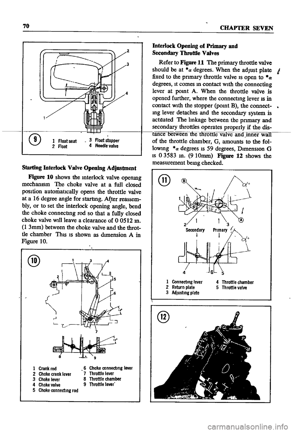
Figure
10
shows
the
Interlock
valve
openmg
mechanISm
The
choke
valve
at
a
full
closed
pOSItion
automatIcally
opens
the
throttle
valve
at
a
16
degree
angle
for
startlng
ter
reassem
bly
or
to
set
the
interlock
opening
angle
bend
the
choke
connectlng
rod
so
that
a
fully
closed
choke
valve
will
leave
a
clearance
of
0
0512
m
1
3mm
between
the
choke
valve
and
the
throt
tle
chamber
ThIS
IS
shown
as
dImension
A
in
Figure
10
@
7
1
Crank
rod
6
Choke
connecting
lever
2
Choke
crank
le
er
7
Throttle
lever
3
Choke
lever
8
Throttle
chamber
4
Choke
VBI
e
9
Throttle
lever
5
Choke
connecting
rod
Interlock
Opening
of
Primary
and
Secondary
Throttle
Valves
Refer
to
Figure
11
The
primary
throttle
valve
should
be
at
a
degrees
When
the
adjust
plate
I
fixed
to
the
pnmary
throttle
valve
IS
open
to
a
degrees
It
comes
In
contact
WIth
the
connecting
lever
at
pOInt
A
When
the
throttle
valve
is
opened
further
where
the
connectIng
lever
IS
in
contact
With
the
stopper
POInt
B
the
connect
mg
lever
detaches
and
the
secondary
system
is
actllated
The
lInkage
between
the
pnmary
and
secondary
throttles
operates
properly
if
the
dis
tance
6etween
theilirotlle
valve
anainner
will
of
the
throttle
chamber
G
amounts
to
the
fol
lowmg
a
degrees
IS
59
degrees
DImenSIon
G
IS
03583
In
910mm
Figure
12
shows
the
measurement
bemg
checked
@
2
Secondary
I
1
Connecting
le
er
2
Return
plate
3
Adjusting
plate
4
Throttle
chamber
5
Throttle
valve
I
1
I
r
t
i
t
r
1
I
j
I
00
I
r
@
Page 97 of 252
91
CHAPTER
NINE
bon
the
serIes
coll
demagnetizes
agatnst
the
shunt
cOIl
The
return
spnng
causes
the
plunger
to
return
to
the
origmal
posItIon
stoppmg
the
starter
The
overrunnmg
clutch
provIdes
for
positIve
meshmg
and
unmeshmg
of
the
pmlOn
gear
and
flywheerrmg
gear
and
perinitStlie
pmlon
to
overrun
the
armature
after
the
engme
has
started
CONSTRUCIlON
A
typical
Datsun
starter
motor
is
shown
m
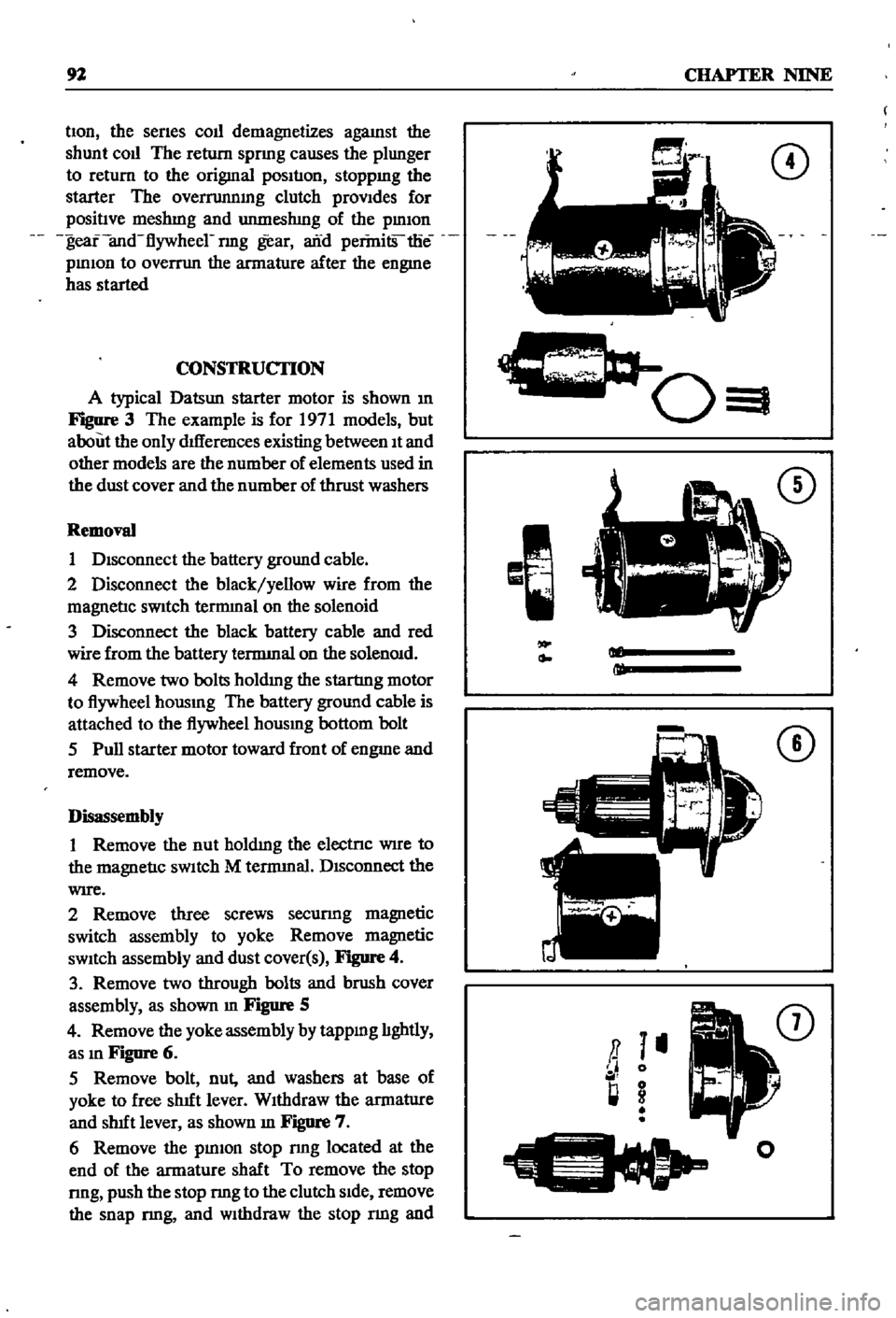
Figure
3
The
example
is
for
1971
models
but
about
the
only
dIfferences
existing
between
It
and
other
models
are
the
number
of
elements
used
in
the
dust
cover
and
the
number
of
thrust
washers
Removal
1
DIsconnect
the
battery
ground
cable
2
Disconnect
the
black
yellow
wire
from
the
magnetIc
sWitch
tennmal
on
the
solenoid
3
Disconnect
the
black
battery
cable
and
red
wire
from
the
battery
tennmal
on
the
solenOId
4
Remove
two
bolts
holdmg
the
startmg
motor
to
flywheel
hOUSIng
The
battery
ground
cable
is
attached
to
the
flywheel
hOUSIng
bottom
bolt
5
Pull
starter
motor
toward
front
of
engme
and
remove
Disassembly
1
Remove
the
nut
holdIng
the
electrIc
WIre
to
the
magnetIc
sWItch
M
tennmal
DIsconnect
the
WIre
2
Remove
three
screws
securmg
magnetic
switch
assembly
to
yoke
Remove
magnetic
sWItch
assembly
and
dust
cover
s
Figure
4
3
Remove
two
through
bolts
and
brush
cover
assembly
as
shown
m
Figure
5
4
Remove
the
yoke
assembly
by
tappmg
lIghtly
as
In
Figure
6
5
Remove
bolt
nut
and
washers
at
base
of
yoke
to
free
shut
lever
WIthdraw
the
armatlIre
and
shut
lever
as
shown
m
Figure
7
6
Remove
the
pInIOn
stop
nng
located
at
the
end
of
the
armature
shaft
To
remove
the
stop
nng
push
the
stop
nng
to
the
clutch
SIde
remove
the
snap
nng
and
Withdraw
the
stop
nng
and
CD
c
0
I
CD
Ml
ml
CD
a
I
II
0
l
g
I
o
Page 152 of 252
CLUTCH
TRANSMISSION
AND
DRIVESHAFI
147
SERVICE
DATA
AND
SPECIFICATIONS
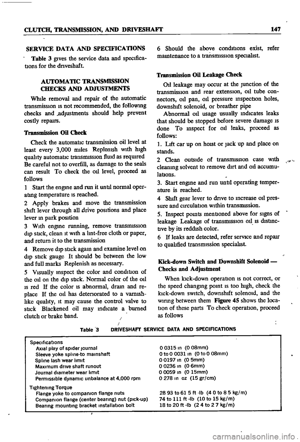
Table
3
gives
the
service
data
and
specIfica
tIons
for
the
dnveshaft
AUTOMATIC
TRANSMISSION
CHECKS
AND
ADJUSTMENTS
Whlle
removal
and
repair
of
the
automatic
transmisSIOn
IS
not
recommended
the
follo
VlIlg
checks
and
adjustments
should
help
prevent
costly
repatrs
Transmission
Oil
Check
Check
the
automatIc
transmission
oil
level
at
least
every
3
000
mlles
Replemsh
With
hIgh
qualIty
automatIc
transmISSIon
flUId
as
reqUIred
Be
careful
not
to
overfill
as
damage
to
the
seals
can
result
To
check
the
011
level
proceed
as
follows
1
Start
the
engme
and
nm
it
untIl
normal
oper
atrng
temperature
IS
reached
2
Apply
brakes
and
move
the
transmission
shut
lever
through
all
drive
pOSItions
and
place
lever
In
park
position
3
WIth
engme
running
remove
tranSmISSIon
dIp
StIck
clean
It
WIth
a
lInt
free
cloth
or
paper
and
return
it
to
the
transmission
4
Remove
dIp
stIck
agam
and
examine
level
on
dIp
stIck
gauge
It
should
be
between
the
low
and
full
marks
Replenish
as
necessary
5
VIsually
InSpect
the
color
and
condItIon
of
the
OIl
on
the
dIp
stIck
Normal
color
of
the
OIl
IS
red
If
the
color
IS
abnormal
dram
and
re
place
If
the
011
has
detenorated
to
a
vamlsh
lIke
qualIty
It
may
cause
the
control
valve
to
stIck
Blackened
oil
may
mdlcate
a
burned
clutch
or
brake
band
6
Should
the
above
condItIons
exist
refer
mamtenance
to
a
transmISSIon
specIalIst
Transmission
Oil
Leakage
Check
011
leakage
may
occur
at
the
Junction
of
the
transmissIon
and
rear
extensIon
011
tube
con
nectors
011
pan
OIl
pressure
mspectIon
holes
downshIft
solenoid
or
breather
pipe
Abnormal
OIl
usage
usually
mdlcates
leaks
that
should
be
stopped
before
severe
damage
IS
done
To
mspect
for
011
leaks
proceed
as
follows
1
LIft
car
up
on
hOISt
or
Jack
up
and
place
on
stands
2
Clean
outsIde
of
transmISSIon
case
With
cleanIng
solvent
to
remove
dIrt
and
011
accumu
latIons
3
Start
engme
and
nm
untIl
operating
temper
ature
is
reached
4
ShIft
gear
lever
to
dnve
to
Increase
011
pres
sure
and
CIrculatIon
WIthin
tranSmISsion
5
Inspect
pOInts
mentIoned
above
for
SIgnS
of
leakage
Leakage
of
transrmSSIOn
011
IS
dIStrnC
tIve
by
its
reddISh
color
6
If
leaks
are
detected
refer
servIce
and
reparr
to
qualIfied
transrmssion
specialISt
Kick
down
Switch
and
Downshift
Solenoid
Checks
and
Adjustment
When
ktck
down
operatIon
IS
not
correct
or
the
speed
changmg
pomt
IS
too
high
check
the
klck
down
SWItch
downshIft
solenOId
and
the
wlDng
between
them
Figure
45
shows
the
loca
tIOn
of
these
parts
To
check
operatIon
proceed
as
follows
Table
3
J
DRIVESHAFT
SERVICE
DATA
AND
SPECIFICATIONS
SpeCifications
Axial
play
of
spider
Journal
Sleeve
yoke
spltne
to
malnshaft
Spline
lash
wear
Itmlt
MaXimum
drive
shaft
runout
Journal
diameter
wear
limit
Penmlsslble
dynamiC
unbalance
at
4
000
rpm
Tightening
Torque
Flange
yoke
to
compaRlon
flange
nuts
CompaRlon
flange
center
bearing
nut
pick
up
Bearing
mounting
bracket
installation
bolt
00315
In
008mm
OtoO
0031
In
OtoO
08mm
00197
In
0
5mm
00236
In
06mm
00059
In
0
15mm
0278
In
oz
15
gr
cm
2893
to
615ft
Ib
40
to
8
5
kg
m
74
to
111
ft
Ib
10
to
15
kg
m
18
to
20
ft
Ib
24
to
2
7
kg
m
Page 193 of 252
J
188
CHAPTER
FOURTEEN
Brake
Pedal
Installation
1
Apply
pedal
grease
to
the
pedal
shaft
sleeves
and
push
rod
cleVIS
pm
2
Installation
is
the
reverse
of
removal
3
Torque
the
fulcrum
pm
to
25
3
to
28
9
ft
lb
3
5
to
4
0
kg
m
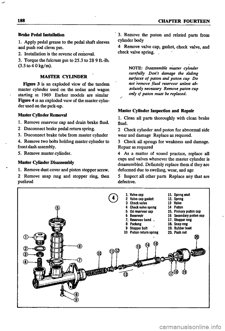
MASTER
CYLINDER
FIgure
3
is
an
exploded
view
of
the
tandem
master
cyhnder
used
on
the
sedan
and
wagon
starting
m
1969
Earher
models
are
sinnlar
Figure
4
IS
an
exploded
View
of
the
master
cyhn
der
used
on
the
pIck
up
Master
Cylinder
Removal
1
Remove
reservOIr
cap
and
drain
brake
f1wd
2
DISconnect
brake
pedal
return
spring
3
Disconnect
brake
tube
from
master
cyhnder
4
Remove
two
bolts
holdmg
master
cyhnder
to
front
dash
assembly
5
Remove
master
cylinder
Master
Cylinder
Disassembly
1
Remove
dust
cover
and
piston
stopper
screw
2
Remove
snap
nng
and
stopper
ring
then
pllShrod
3
Remove
the
piston
and
related
parts
from
cyhnderbody
4
Remove
valve
cap
gasket
check
valve
and
check
valve
spring
NOTE
DISassemble
master
cylmder
carefully
Don
t
damage
the
slldmg
surfaces
of
pISton
and
pISton
cup
Do
not
remove
flUId
reservOlT
unless
ab
solutely
necessary
Remove
pISton
cup
only
If
pISton
must
be
replaced
r
Master
Cylinder
Inspection
nnd
Repair
1
Clean
all
parts
thoroughly
with
clean
brake
fiwd
2
Check
cyhnder
and
piston
for
abnormal
side
wear
and
damage
Replace
as
reqUIred
3
Check
all
spnngs
for
weakness
and
damage
Reparr
as
reqUIred
4
As
a
matter
of
sound
practIce
replace
all
cups
and
valves
whenever
the
master
cyhnder
is
dISassembled
DefinItely
replace
them
1f
they
are
deformed
due
to
swellmg
wear
and
age
5
Inspect
all
other
parts
Replace
any
that
are
defective
CD
1
Valve
cap
2
Valve
cap
gasket
3
Check
valve
4
Check
valve
spnng
5
011
reservoIr
cap
6
Reservoir
7
ReservOir
band
8
Paclang
9
Stopper
bolt
10
PIston
return
spnng
11
Sprmg
seat
12
Spnng
13
Valve
14
PIston
15
Pnmary
pIston
cup
16
Secondary
piston
cup
17
Stopper
nng
18
Snap
nng
19
Rubber
boot
20
Push
rod