1968 DATSUN 510 wheel alignment
[x] Cancel search: wheel alignmentPage 5 of 252
CHAPTER
TWELVE
DIFFERENTIAL
REAR
AXLE
AND
REAR
SUSPENSION
149
DIfferentIal
Rear
axle
and
suspension
Codspnng
Shock
absorber
Rear
suspensIOn
arm
Rear
axle
shaft
Wheel
beanngs
Seals
Rear
spnng
Axle
case
SpecificatIons
CHAPTER
THIRTEEN
FRONT
AXLE
FRONT
SUSPENSION
AND
STEERING
168
Wheel
hub
and
bearmg
StabilIzer
TenSion
rod
Spnng
and
strut
assembly
Transverse
lInk
Lower
ball
Jomt
Front
suspension
adjustment
Wheel
alignment
Posture
adJustment
Steenng
system
SpeCificatIons
CHAPTER
FOURTEEN
BRAKES
187
Brake
pedal
Master
cylInder
Front
diSC
brakes
Rear
brakes
Front
drum
brakes
Wheel
cylInders
Brake
system
bleedIng
Handbrake
Service
data
and
speCificatIons
CHAPTER
FIFTEEN
BODY
ELECTRICAL
SYSTEM
Wmng
SWitches
and
fuses
Instrument
meters
and
panels
Heater
205
Wmdshleld
wipers
Wmdslueld
washers
Headlamps
WIrIng
diagrams
CHAPTER
SIXTEEN
BODY
223
Front
body
trIm
Bumpers
Hood
lock
control
Doors
Door
locks
and
regulators
Trunk
lId
and
rear
bumper
Seats
Tad
gate
INDEX
235
I
Page 18 of 252

TROUBLESHOOTING
13
trouble
may
also
be
worn
bearings
Remove
the
alternator
and
repair
ENGINE
These
procedures
assume
the
starter
cranks
the
engme
over
normally
If
not
refer
to
Starter
section
m
this
chapter
1
Engme
won
t
start
Could
be
caused
by
the
IgOltlon
or
fuel
problems
First
determine
If
high
voltage
to
spark
plug
occurs
To
do
thiS
dISconnect
one
of
the
spark
plug
wires
Hold
the
exposed
wrre
termlOal
y
to
Y2
lOch
from
ground
any
metal
in
engine
com
partment
With
an
msulated
screwdriver
Crank
the
engme
over
If
sparks
do
not
Jump
to
ground
or
the
sparks
are
very
weak
the
trouble
may
be
10
the
IgnitIOn
system
See
Ignition
System
Trou
bleshootmg
to
further
check
If
sparks
occur
properly
the
trouble
may
be
10
the
fuel
system
See
Fuel
System
Troubleshootmg
2
Engme
misses
steadily
Remove
one
spark
plug
wrre
at
a
tune
and
ground
the
wrre
If
engme
mISs
increases
that
cyhnder
was
work
109
properly
Reconnect
the
wire
and
check
the
others
When
a
wire
IS
dIs
connected
and
engme
miss
remams
the
same
that
cylinder
IS
not
finng
Check
spark
as
descnbed
10
Step
1
If
no
spark
occurs
for
one
cyhnder
only
check
dlStnbutor
cap
wrre
and
spark
plug
If
spark
occurs
prop
erly
check
compressIOn
and
mtake
maOlfold
vacuum
to
ISolate
the
trouble
3
Engme
misses
erratlcally
at
all
speeds
Interrmttent
trouble
can
be
difficult
to
find
It
could
be
ill
the
Ignition
system
exhaust
system
or
fuel
system
Follow
troubleshooting
proce
dures
for
these
systems
carefully
to
isolate
the
trouble
4
Engme
misses
at
Idle
only
Trouble
could
exist
anywhere
ill
IgOltlon
system
Follow
Ignition
TroubleshootlOg
procedure
care
fully
Trouble
could
also
eXist
10
the
carburetor
Idle
crrcult
Check
Idle
mIXture
adjustment
and
check
for
restnctions
m
the
idle
crrcUlt
5
Engme
misses
at
high
speed
only
Problems
could
be
ill
the
fuel
or
IgOltlon
systems
heck
accelerator
pump
operation
fuel
pump
dehvery
fuel
hnes
etc
as
descnbed
under
Fuel
System
Troubleshootillg
Also
check
spark
plugs
and
wrres
6
Low
performance
at
all
speeds
poor
acceleratIOn
Trouble
usually
ill
IgOltlon
or
fuel
system
Check
each
With
the
appropnate
troubleshooting
pro
cedure
7
ExceSSive
fuel
consumptIOn
Could
be
caused
by
a
Wide
variety
of
seemmgly
unrelated
factors
Check
for
clutch
shppage
brake
drag
defective
wheel
beanngs
or
poor
front
end
alignment
Check
IgOltlOn
system
and
fuel
system
8
011
pressure
lamp
does
not
light
when
IgmtlOn
switch
IS
on
Check
the
alternator
warning
lamp
If
it
ISn
t
on
either
go
to
Step
1
Chargmg
System
Trouble
shootlOg
If
only
the
oil
pressure
lamp
IS
off
open
the
englOe
compartment
hd
and
locate
the
oil
pressure
sender
on
the
block
near
the
oil
filter
Make
sure
the
wrre
is
connected
to
the
sender
and
makmg
good
contact
Pull
the
wrre
off
and
ground
it
If
the
lamp
hghts
replace
the
sender
If
the
lamp
does
not
light
replace
the
lamp
9
011
pressure
lamp
lights
or
flickers
when
engme
IS
runmng
Indicates
low
or
complete
loss
of
oil
pressure
Stop
the
englOe
unmedmtely
coast
to
a
stop
With
the
clutch
dISengaged
Tlus
may
simply
be
caused
by
a
low
oil
level
or
an
overheatmg
en
glOe
Check
the
oil
level
and
fan
belt
tensIOn
Check
for
a
shorted
oil
pressure
sender
with
an
ohmmeter
or
a
contlOulty
tester
Remove
and
clean
the
oil
dipstick
and
check
oil
level
and
condition
RepleOlsh
or
replace
the
oil
as
re
qurred
Listen
for
unusual
nOISes
mdlcatmg
dam
aged
beanngs
etc
Do
not
re
start
the
engine
until
you
know
why
the
hght
went
on
and
are
sure
that
the
problem
has
been
corrected
IGNITION
SYSTEM
This
procedure
assumes
the
battery
IS
ill
good
enough
condition
to
crank
the
engme
at
a
normal
rate
Page 21 of 252
16
CHAPTER
TIlREE
sary
Also
check
all
parts
for
mlSaltgnment
and
uneven
wear
TRANSMISSION
1
Difficult
to
mesh
gears
Make
certam
the
clutch
pressure
plate
and
re
lease
beanng
are
m
good
condItion
The
trouble
can
be
caused
by
worn
gears
shaft
and
or
bear
mgs
DISassemble
and
repaIr
as
requIred
Also
can
be
caused
by
msufficlent
operatmg
stroke
due
to
worn
or
loose
sltdmg
parts
or
a
defective
synchronIZer
DIsassemble
carefully
InSpect
and
replace
as
requIred
2
Gears
slip
out
of
mesh
Generally
thIS
trouble
occurs
when
the
mterlock
plunger
check
ball
and
or
spnng
IS
weakened
or
worn
The
trouble
can
also
be
caused
by
worn
fork
rod
ball
groove
damaged
bearings
or
dam
aged
gears
DIsassemble
carefully
mspect
and
replace
as
required
3
NOIse
If
nOISes
are
heard
wIth
the
engme
idlmg
and
the
clutch
disengaged
the
nOIse
IS
probably
conung
from
the
transmISSIOn
Several
Items
can
cause
nOISes
either
smgly
or
m
combmatIon
Check
the
qualIty
and
quantity
of
lubrIcant
in
the
trans
mISSIon
Replace
or
replenISh
as
necessary
Worn
bearIngs
wIll
usually
produce
a
lugh
humming
at
hIgh
speed
and
a
cycltc
knockIng
sound
at
low
speed
Worn
or
damaged
splInes
and
bushmgs
will
also
cause
nOIse
BRAKES
1
Brake
pedal
goes
to
floor
There
are
numerous
causes
for
thIS
includIng
excessIvely
worn
Itnmgs
aIr
in
the
hydraultc
sys
tem
leaky
brake
lmes
leaky
wheel
cylmders
or
leaky
or
worn
master
cylmder
Check
for
leaks
and
thIn
brake
linmgs
Bleed
and
adjust
the
brakes
If
thIS
doesn
t
cure
the
trouble
rebwld
wheel
cylmders
a
nd
or
master
cylmder
2
Spongy
pedal
Normally
caused
by
aIr
m
the
system
blee
d
and
adjust
the
brakes
3
Brakes
pull
Check
brake
adjustment
Also
check
for
contam
inated
brake
Itmngs
from
leaks
leaky
wheel
cyltnders
loose
caltpers
frozen
or
seIZed
pIstons
and
restrIcted
brake
lmes
or
hoses
In
addItion
check
front
end
alignment
and
suspensIOn
dam
age
such
as
broken
front
or
rear
sprmgs
shocks
etc
Check
condItIon
of
tIres
4
Brakes
squeal
or
chatter
Check
brake
lmmg
thickness
and
brake
drum
roundness
Ensure
that
the
shoes
have
cham
ferred
ends
and
are
not
loose
Inspect
the
condI
tion
of
the
rotors
on
the
front
wheel
dISC
brakes
to
make
certain
they
are
not
scored
or
damaged
Clean
away
all
dIrt
on
shoes
pads
rotors
or
drums
5
Draggmg
brakes
Check
brake
adjustment
includmg
handbrake
Check
for
broken
or
weak
shoe
return
springs
swollen
rubber
parts
due
to
unproper
brake
flUId
or
other
contammatIon
Clean
or
replace
de
fectIve
parts
6
Hard
pedal
Check
brake
linmgs
for
contammation
Also
check
for
restrIcted
brake
lines
and
hoses
7
High
speed
fade
Check
for
dIstorted
or
out
of
round
drums
and
contamInated
brake
lmmgs
Make
certam
the
recommended
brake
flUId
IS
used
Dram
entIre
system
and
refill
If
In
doubt
8
Pulsatmg
pedal
Check
for
dIStorted
or
out
of
round
drums
or
rotors
Check
for
excessIVe
brake
dISC
run
out
STEERING
AND
SUSPENSION
NOTE
Unusual
steermg
pullmg
or
wandermg
IS
usually
caused
by
bent
or
otherwise
mIsaligned
suspenszon
parts
Because
of
the
speCialized
equIp
ment
reqUired
to
evaluate
and
correct
these
faults
It
IS
recommended
t
tat
servIce
to
the
steermg
and
suspension
system
be
referred
to
your
Datsun
dealer
oca
quallfied
specrallst
m
thiS
field
1
VibratIOn
felt
m
steermg
wheel
VIbratIon
can
be
caused
by
several
thmgs
includ
ing
lll1proper
aIr
pressure
m
tIres
uneven
wear
Page 22 of 252

TROUBLESHOOTING
17
of
tIre
loose
wheels
unproper
adjustment
or
wear
of
front
wheel
bearIngs
faulty
wheel
align
ment
or
wear
of
transverse
lInk
and
tension
rod
bushings
Inspect
all
parts
carefully
for
wear
or
damage
Replace
or
replUI
parts
as
required
2
Shock
transmltled
through
steering
wheel
This
is
usually
most
noticeable
when
traveling
over
bad
roads
at
relatively
high
speeds
Causes
Include
damage
to
the
idler
ann
insuffiCient
tIghtening
of
steenng
gear
box
wear
of
the
steer
Ing
linkage
and
wear
of
the
suspension
ball
joint
Inspect
all
parts
for
wear
or
damage
Refer
to
Chapter
ThIrteen
for
service
or
repair
you
can
perform
and
for
procedures
which
should
be
referred
to
your
deal
r
3
Shlmmymg
This
is
usually
most
noticeable
when
a
specIfic
speed
IS
attained
and
will
normally
repeat
at
that
speed
Causes
are
generally
unbalanced
wheels
unproper
adjustment
of
steenng
gear
insuffi
cient
backlash
malfunction
of
the
shock
ab
sorbers
or
loose
bolts
for
the
strut
mountIng
Reparr
or
replace
defective
parts
as
required
Refer
to
Chapter
Thirteen
4
Wandermg
of
car
m
one
dlrectlOnl
This
problem
can
be
caused
by
improper
air
pressure
loose
wheel
nuts
difference
in
tire
tread
wear
from
left
to
right
side
Incorrect
adjustment
of
wheel
bearings
defectIve
wheel
beanngs
collapsing
or
twistIng
of
front
spnng
or
Incorrect
wheel
alignment
Also
binding
of
the
brake
shoes
worn
bushings
in
the
transverse
link
or
the
tension
rod
and
deformation
of
s
enng
lInkage
and
suspension
link
can
cause
wander
Carefully
iuspect
all
parts
for
looseness
and
wear
and
re
place
or
repaIr
as
required
In
some
c
ases
a
de
fective
rear
suspension
may
also
cause
the
vehicle
to
wander
5
InstabIlity
Instability
can
be
caused
by
unproper
tIre
pres
sures
worn
bushings
in
the
transverse
link
and
tension
rod
mcorrect
wheel
alignment
worn
steenng
linkage
Incorrect
adjustment
of
steer
ing
gear
and
unbalanced
wheels
Inspect
all
parts
carefully
for
wear
and
damage
Adjust
repair
or
replace
as
required
6
Heavy
feelmg
m
steering
This
can
be
caused
by
improper
tIre
pressures
insuffiCient
or
contamInated
lubncant
in
gear
box
damage
or
insuffiCient
grease
In
suspeuslon
ball
Joint
damaged
or
badly
adjusted
wheel
bearIngs
worn
or
damaged
steermg
gear
dam
age
of
upper
strut
bearing
and
mterference
of
steenng
column
With
turn
signal
SWitch
Inspect
all
parts
carefully
for
wear
and
damage
Adjust
repair
or
replace
as
required
7
ExceSSIve
play
m
steermg
wheel
This
is
usually
caused
by
Incorrect
adjustment
of
the
steenng
gear
worn
bushings
in
the
steering
linkage
or
Idler
arm
mcorrect
adjustment
of
the
front
wheel
bearings
worn
bushIngs
in
the
trans
verse
lInk
and
tension
rod
Carefully
inspect
all
parts
for
wear
or
damage
Adjust
repair
or
re
place
as
reqUIred
TIRE
WEAR
ANALYSIS
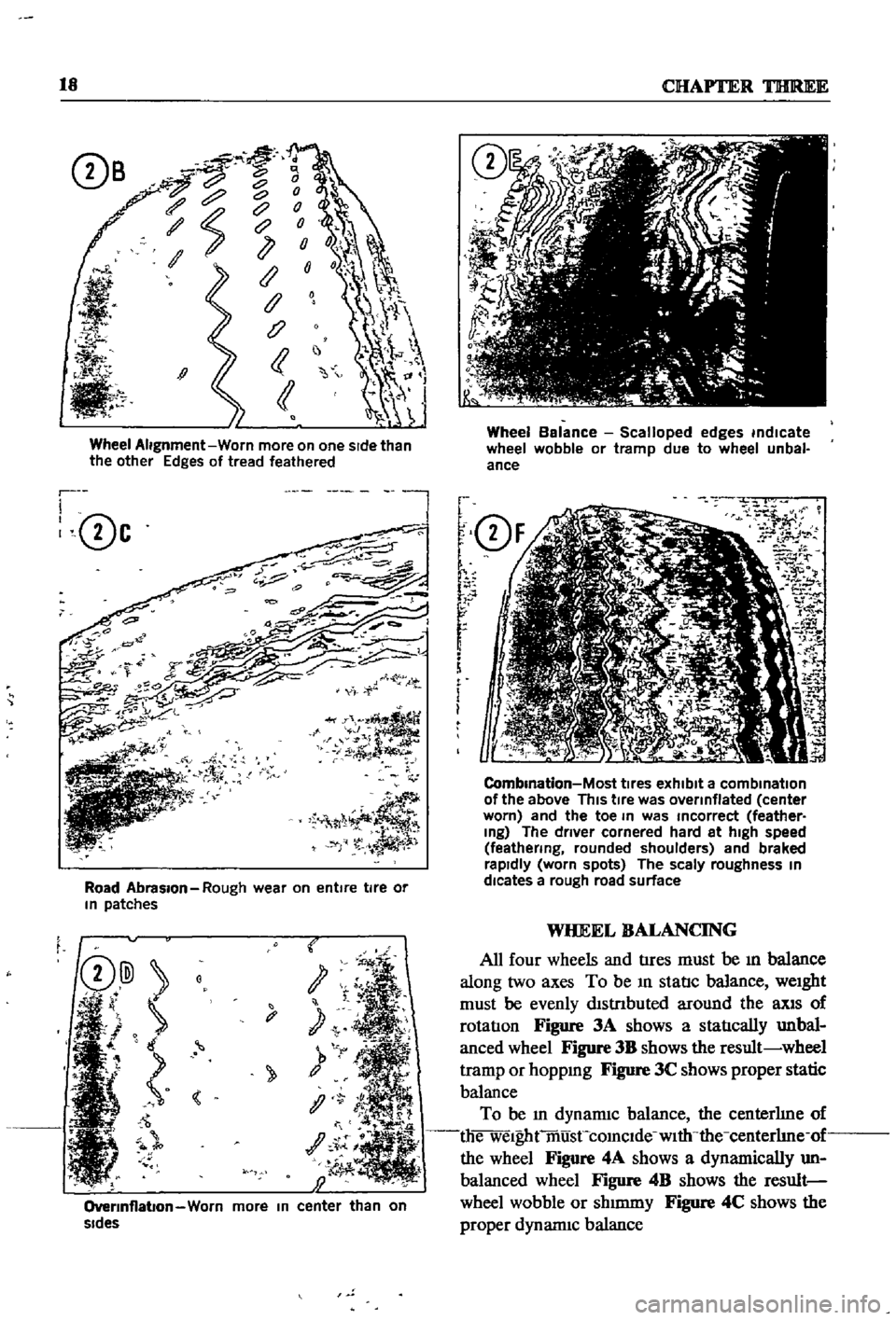
Abnormal
tIre
wear
should
always
be
ana
lyzed
to
deternune
the
cause
The
most
common
are
Incorrect
tIre
pressure
improper
dnving
overloading
and
Incorrect
wheel
ahgDment
Figures
2A
through
2F
identify
wear
patterns
and
mdicate
likely
causes
Of
I
1
l
D
1
Undennflatlon
Worn
more
on
Sides
than
In
center
Page 23 of 252
18
CHAP1
lER
THlREE
c
c
c
ce
J
1
Ii
j
Wheel
Alignment
Worn
more
on
one
sIde
than
the
other
Edges
of
tread
feathered
r
I
0c
l
Road
Abrasion
Rough
wear
on
entire
tire
or
In
patches
t
y
1
OverInflabon
Worn
more
In
center
than
on
sides
Wheel
Balance
Scalloped
edges
indicate
wheel
wobble
or
tramp
due
to
wheel
unbal
ance
f
Q
F
r
r
r
f
i
m
i
O
2
7
iK
J
1
J
i
i
5J
CombInation
Most
tIres
exhibit
a
combination
of
the
above
This
tIre
was
overinflated
center
worn
and
the
toe
In
was
Incorrect
feather
Ing
The
driver
cornered
hard
at
high
speed
feathering
rounded
shoulders
and
braked
rapidly
worn
spots
The
scaly
roughness
In
dlcates
a
rough
road
surface
WHEEL
BALANCING
All
four
wheels
and
tIres
must
be
ill
balance
along
two
axes
To
be
ill
statIc
balance
weight
must
be
evenly
dlstnbuted
around
the
llXlS
of
rotatIon
Figure
3A
shows
a
statIcally
unbal
anced
wheel
Figure
3B
shows
the
result
wheel
tramp
or
hoppmg
Figure
3C
shows
proper
static
balance
To
be
ill
dynamiC
balance
the
centerhne
of
die
welghtmusCcomclde
with
the
centerhne
of
the
wheel
Figure
4A
shows
a
dynamically
un
balanced
wheel
Figure
4B
shows
the
result
wheel
wobble
or
shmuny
Figure
4C
shows
the
proper
dynannc
balance
Page 180 of 252
FRONT
AXLE
FRONT
SUSPENSION
AND
STEERING
175
2
Remove
bolt
cormectIng
strut
and
knuckle
arm
3
Remove
cotter
pm
and
lower
ball
Joint
4
Separate
lower
ball
Jomt
from
knuckle
arm
5
Remove
bolts
for
lower
ball
Jomt
Separate
transverse
lmk
from
lower
ball
Joint
6
Inspect
ball
Jomt
and
dust
cover
for
wear
or
damage
Replace
as
requIred
If
end
play
m
the
aXial
dIrectIon
of
the
ball
Jomt
exceeds
00012
to
0
0136
m
0
03
to
0
6mm
replace
It
7
Install
ball
Jomt
m
the
reverse
of
removal
Grease
It
through
the
grease
mpple
Take
care
to
fill
the
caVity
slowly
so
that
grease
does
not
come
out
from
the
clamp
portIon
8
Torque
bolts
as
follows
Lower
Ball
JOint
to
Transverse
Link
Ball
Stud
Nut
13
7
to
18
1
fl
Ib
19
to
25
kgfm
398
to
55
0
fl
Ib
55
to
76
kgfm
43
4
to
57
8
flAb
60
to
80
kgfm
35
4
to
45
6
flAb
49
to
63
kgfm
87
to
12
3
fl
lb
12
to
17
kgfm
Knuckle
Ann
to
Strut
TenSion
Rod
to
Transverse
Link
Stabilizer
to
Transverse
Link
FRONT
SUSPENSION
ADJUSTMENT
AND
WHEEL
ALIGNMENT
SEDAN
AND
WAGON
Due
to
the
speclahzed
eqUIpment
required
front
suspensIOn
adJustment
and
wheel
ahgn
ment
should
be
referred
to
a
Datsun
dealer
or
front
end
speciahst
The
followmg
specmcations
apply
to
the
sedan
and
wagon
Sedan
Wagon
Caster
1
40
20
00
Camber
1
00
20
10
King
Pin
Incllnallon
8000
7050
Toe
In
0236
to
0
354
In
0118
to
0
236
In
6
to
9mm
3
to
6mm
Steenng
Angle
In
38
to
390
38
to
390
Steenng
Angle
Out
22030
to
330
30
220
30
to
330
30
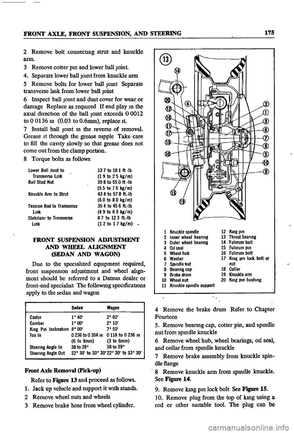
Front
Axle
Removal
Pick
up
Refer
to
Figure
13
and
proceed
as
follows
1
Jack
up
vehIcle
and
support
it
With
stands
2
Remove
wheel
nuts
and
wheels
3
Remove
brake
hose
from
wheel
cylinder
@
@
1
Knuckle
spindle
2
Inner
wheel
beanng
3
Outer
wheel
beanng
4
011
seal
5
Wheel
hub
6
Washer
7
Spindle
nut
8
Beanng
cap
9
Brake
drum
10
Wheel
nut
11
Knuckle
spindle
support
12
KUlg
pin
13
Thrust
beanng
14
fulaum
bolt
15
Fulcrum
pin
16
Fulaum
bolt
17
King
pin
lock
bolt
or
nut
18
Collar
19
Knuckle
ann
20
King
pin
busllIng
4
Remove
the
brake
drum
Refer
to
Chapter
Fourteen
5
Remove
bearmg
cap
cotter
pin
and
spmdle
nut
from
spmdle
knuckle
6
Remove
wheel
hub
wheel
bearings
011
seal
and
collar
from
spmdle
knuckle
7
Remove
brake
assembly
from
knuckle
spin
dle
flange
8
Remove
knuckle
arm
from
spmdle
knuckle
See
Figure
14
9
Remove
kmg
pm
lock
bolt
See
Figure
15
10
Remove
plug
from
the
top
of
kmg
using
a
rod
or
other
SUItable
tool
The
plug
can
be
Page 187 of 252
182
CHAPTER
TIllRTEEN
@
AdJust
the
anchor
bolt
adJustmg
nut
until
the
vehicle
posture
IS
correct
One
complete
turn
of
the
nut
will
change
the
vertIcal
measurement
by
approXlmately
0
133
in
3
Smm
WHEEL
AUGNMENT
Due
to
the
speclahzed
eqwpment
required
wheel
ahgnment
should
be
referred
to
a
Datsun
dealer
or
a
wheel
alignment
specIahst
The
fol
lowmg
specmcatIons
apply
to
the
pick
up
Caster
Camber
Kmg
Pm
Inclmatlon
Toe
In
1
50
1
15
6015
o
0787
to
0
1181
In
2
to
3mm
360
31
Steenng
Angle
Inner
Steenng
Angle
Outer
STEERING
SYSTEM
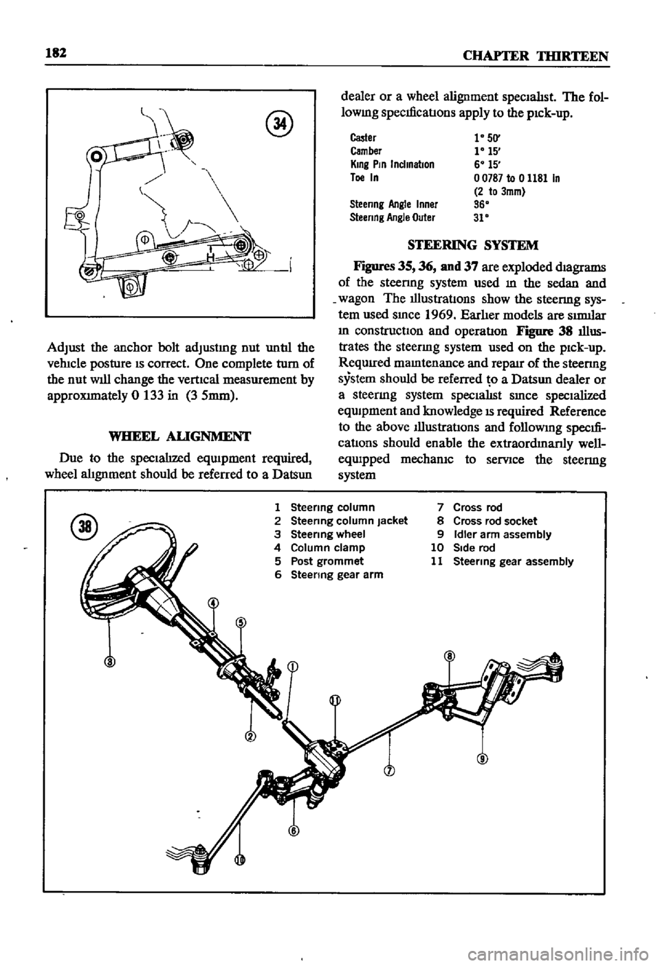
Figures
35
36
nnd
37
are
exploded
magrams
of
the
steenng
system
used
m
the
sedan
and
wagon
The
illustratIons
show
the
steenng
sys
tem
used
smce
1969
Earher
models
are
SImllar
m
constructiOn
and
operatIon
Figure
38
illus
trates
the
steenng
system
used
on
the
pick
up
ReqUIred
mamtenance
and
repaJr
of
the
steenng
system
should
be
referred
o
a
Datsun
dealer
or
a
steermg
system
specialISt
smce
specialized
eqwpment
and
knowledge
IS
required
Reference
to
the
above
Illustrations
and
followmg
specm
cations
should
enable
the
extraordmanly
well
equipped
mechanIC
to
serVice
the
steermg
system
1
Steenng
column
2
Steermg
column
Jacket
3
Steenng
wheel
4
Column
clamp
5
Post
grommet
6
Steenng
gear
arm
7
Cross
rod
8
Cross
rod
socket
9
Idler
arm
assembly
10
Side
rod
11
Steermg
gear
assembly
Page 245 of 252
l
INDEX
239
Rear
suspensIOn
wagon
Removal
40
92
Servlcmg
161
Termmals
94
Tightening
torques
162
Test
diagnosIs
97
Testmg
96
Troubleshootmg
10
5
Steenng
also
see
Suspension
front
I
Exploded
views
182
185
L
Seats
SpecIfications
186
DescnptIon
228
Troubleshooting
16
Exploded
View
front
4
door
sedan
232
SuspensIOn
front
pick
up
Exploded
VIew
front
pick
up
228
Axle
removal
175
Service
hmts
4
Inspection
and
repair
179
Shock
absorbers
sedan
154
Installation
179
Shock
absorbers
wagon
162
Posture
adjustment
181
Spark
plugs
Removal
177
CondlllOn
chart
21
Wheel
abgnment
182
InspectIon
and
servlcmg
21
Wheel
bearmg
adjustment
177
Recommended
types
112
Suspension
front
sedan
and
wagon
SpecificatIOns
and
tables
Inspection
and
repair
176
Adjustment
and
wheel
alignment
175
InstallatIOn
177
Brake
service
data
203
204
Lower
ball
Jomt
174
Brakes
203
204
Spnng
and
strut
assembly
173
Camshaft
beanngs
48
Stabilizer
173
Caster
and
camber
sedan
and
wagon
175
TenSIOn
rod
173
Clutch
134
Transverse
bnk
174
Clutch
service
data
134
Wheel
beanngs
177
Connectmg
rod
beanng
underslzes
52
Wheel
hubs
and
bearmgs
168
173
Dlstnbutor
112
SWItches
Dnveshaft
147
DescnptIon
205
Dnveshaft
service
dala
147
Exploded
View
through
1969
208
Engme
60
61
Exploded
view
1970
1972
207
Engme
service
data
60
61
General
4
Mam
bearmg
underslzes
52
T
Piston
rmg
gap
50
Rear
suspenSIOn
pick
up
167
Tail
gate
228
233
Rear
suspensIOn
torques
wagon
162
TenSIOn
rod
sedan
and
wagon
173
Steermg
186
Thermostat
TransmiSSion
manual
144
DescnptIon
89
TransmiSSion
service
data
manual
144
Inspection
and
replacement
89
Valve
spnng
47
Removal
89
Sprmg
and
strut
assembly
sedan
and
wagon
173
Tires
Spnngs
sedan
154
Wear
analYSIS
17
Stabilizer
sedan
and
wagon
173
TransmiSSion
automatic
Starter
Downshift
solenOid
147
Armature
95
Inhlbllor
SWItch
148
Beanngs
96
Kick
down
SWitch
147
Brush
holder
96
Lmkage
mspectIon
and
adjustment
148
Brushes
and
lead
WIre
95
011
checks
147
Cleaning
mspectIon
and
repair
94
Oil
leakage
147
Construcllon
92
TransmiSSion
manual
Disassembly
92
DescnptIon
134
Exploded
View
93
Disassembly
138
Field
COIl
94
Exploded
view
138
Magnetic
SWItch
96
Gear
assembly
exploded
view
139
Magnetic
SWItch
assembly
test
97
Inspection
and
repair
141
Operation
91
Installation
143
Overrunnmg
clutch
96
Reassembly
and
adjustment
142
Reassembly
96
Removal
134