1968 DATSUN 510 torque
[x] Cancel search: torquePage 7 of 252

2
CHAPTER
ONE
Sedan
Four
speed
Floor
Shift
P51O
UT
Pl5lO
T
Pl510
UT
P51O
UA
Pl5lO
A
Pl510
UA
AutomatIc
Three
speed
Wagon
Four
speed
Floor
Shift
WP510
UT
WPl510
T
WPL510
UT
WP510
UA
WPl5lO
A
WPL510
UA
AutomatIc
Three
speed
PIl
Il
up
Four
speed
Floor
Shift
Pl521
TU
Pl521
TN
CD
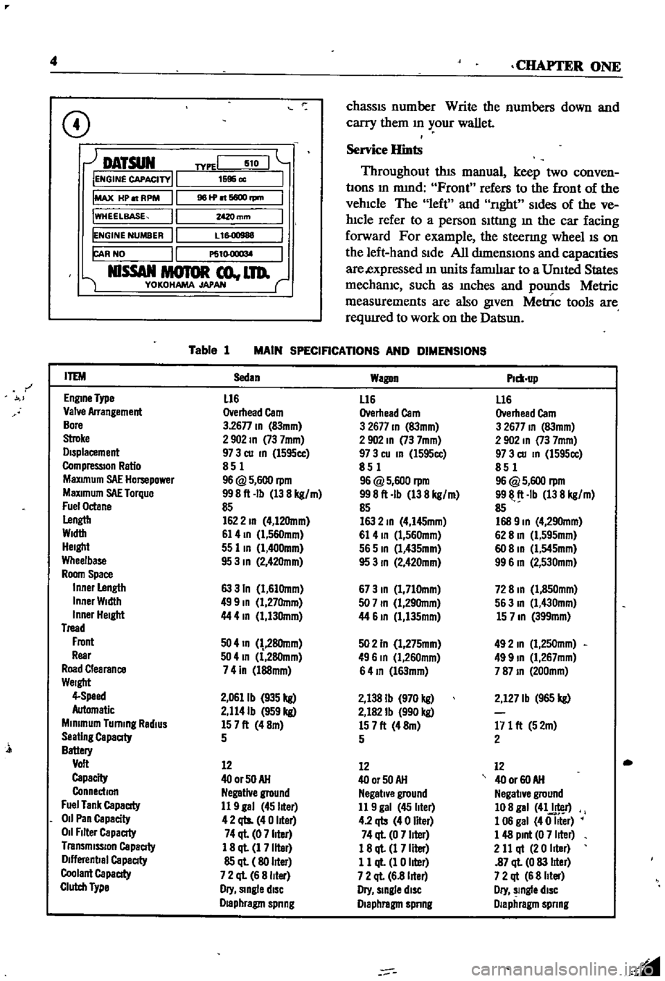
MAIN
SPECIFICATIONS
AND
DIMENSIONS
Table
1
covers
general
specIfications
and
dImensIOns
DetaIled
system
specIficatIOns
ill
cludmg
clearances
tolerances
and
torque
tlght
enrng
mformatlOn
are
presented
Wlthm
each
chapter
Parts
Replacement
When
you
order
parts
from
the
dealer
or
other
parts
dlstnbutor
always
order
by
engme
and
d
1
Page 9 of 252

4
CHAPTER
ONE
chassIs
number
Write
the
numbers
down
and
carry
them
ill
your
wallet
Service
Hints
Throughout
thIs
manual
keep
two
conven
bons
ill
mmd
Front
refers
to
the
front
of
the
vehicle
The
left
and
nght
sides
of
the
ve
hicle
refer
to
a
person
sittIng
ill
the
car
facing
forward
For
example
the
steenng
wheelIS
on
the
left
hand
Side
All
dimensIOns
and
capacities
are
expressed
ill
units
fanuhar
to
a
Umted
States
mechaniC
such
as
illches
and
pounds
Metric
measurements
are
also
given
Metnc
tools
are
reqUITed
to
work
on
the
Datsun
CD
DATSUN
IENGINE
CAPACITY
IMAX
HP
RPM
IWHEELBASE
IENGINE
NUMBER
FAR
NO
NlSSAN
MOTOR
co
LTD
YOKOHAMA
JAPAN
TYPEI
510
1595
cc
961P
6600
rpm
mm
L
1
00988
P61
l
O
1
l
M
Table
1
MAIN
SPECIFICATIONS
AND
DIMENSIONS
r
ITEM
Sedan
Wagon
Plm
up
EnglDe
Type
L16
L16
L16
Valve
Arrangement
Overhead
Cam
Overhead
Cam
Overhead
Cam
Bore
3
26n
ID
83mm
3
2677
ID
83mm
3
2677
ID
83mm
Stroke
2902
ID
73
7mm
2
902
ID
73
7mm
2
902
In
73
7mm
Displacement
97
3
cu
ID
l595cc
97
3
cu
In
l595cc
97
3
cu
ID
1595cc
CompressIOn
Ratio
851
851
851
MaXimum
SAE
Hompower
96
@
5
600
rpm
96
@
5
600
rpm
96
@
5
600
rpm
MaXimum
SAE
Torque
998ft
Ib
138
kg
m
998ft
Ib
138
kg
m
9911
ft
Ib
138
kg
m
Fuel
Octane
85
85
85
Lengtb
1622
ID
4
12Omm
163
2
ID
4
I45mm
168
9
ID
4
290mm
Width
61
4
ID
l
560mm
61
4
ID
1
560mm
62
8
In
Cl
595mm
Height
55
lID
1
400mm
565
ID
Cl
435mm
60
8
ID
Cl
545mm
Wheelbase
95
3
ID
2
42Omm
95
3
ID
2
420mm
99
6
In
2
530mm
Room
Space
Inner
Length
63
3
In
1
61Omm
673
ID
1
710mm
72
8
ID
1
850mm
Inner
Width
499
ID
1
27Omm
507
ID
1
29Omm
563
In
1
430mm
Inner
Height
44
4
In
1
130mm
44
61D
1
135mm
15
7
ID
399mm
Tread
Front
50
4
ID
28Omm
502
In
1
275mm
492
In
1
250mm
Rear
504
In
1
280mm
496
In
Cl
260mm
499
ID
1
267mm
Road
Clearance
741n
l88mm
64
ID
l63mm
787
ID
200mm
Weight
4
Speed
2
0611b
935
kg
2
138
Ib
970
kg
2
127
Ib
965
kg
Automatic
2
114Ib
959
kg
2
182
Ib
990
kg
Minimum
Turning
RadiUS
157ft
48m
157ft
48m
171
ft
52m
Seating
Capaaty
5
5
2
Battery
Volt
12
12
12
Capacity
400rSOAH
400r50AH
40
or
60
AH
Connection
Negative
ground
Negative
ground
Negative
ground
Fuel
Tank
Capaaty
11
9
gal
45
liter
11
9
gal
45
liter
108
gal
41J
r
011
Pan
Capacity
42
qts
40
liter
4
2
qb
40
liter
1
06
gal
40
Iller
011
Filter
Capaaty
74
ql
07
liter
74
ql
0
7
liter
1
48
Pint
0
7
liter
Transmission
Capaaty
1
8
ql
1
7
liter
18
ql
1
7
Iller
2
11
qt
20
Iller
Dlflerenbal
Capaaty
85
ql
80
liter
11
ql
1
0
liter
87
ql
0
83
lIter
Coolant
Capaaty
7
2
ql
6
8
liter
7
2
ql
6
8
lIter
7
2
qt
6
8
Iller
Clutch
Type
Dry
Single
diSC
Dry
slDgle
diSC
Dry
slDgle
diSC
Draphragm
spnng
Diaphragm
spnng
Diaphragm
spnng
l
Page 25 of 252

CHAPTER
FOUR
ENGINE
AND
IGNITION
TUNE
UP
For
best
performance
and
economy
care
must
be
taken
in
perfornnng
tune
ups
While
accuracy
is
required
the
task
IS
not
d1flicult
if
the
steps
m
tlus
chapter
are
followed
carefully
Cars
used
pnmarily
m
CIty
stop
and
go
dnv
ing
WIll
reqwre
attention
more
frequently
than
those
used
on
highways
ThIs
is
because
the
engme
does
not
reach
full
operatIng
temperature
ConsequentlY
valves
tend
to
stick
compression
drops
and
engme
operatIon
becomes
rough
A
tune
up
IS
adVISable
every
6
000
miles
or
sooner
dependmg
on
type
of
driving
Every
12
000
nu1es
the
spark
plugs
and
ignitIon
break
er
pomts
should
be
replaced
not
Just
cleaned
and
adjusted
A
mmor
tune
up
consISts
of
checking
battery
condItIon
cleanmg
gapping
or
replacmg
spark
plugs
and
dIstnbutor
breaker
pomts
adjustIng
dIStnbutor
dwell
angle
adjusting
IgnitIon
tun
mg
and
settIng
the
carburetor
Idle
mixture
and
idle
speed
A
major
wne
up
includes
the
above
items
plus
igllltIon
compressIOn
valve
clear
ance
carburetor
emISsion
control
deVIce
and
electncal
checks
and
adjustments
Tune
up
Equipment
Required
The
follOWIng
eqUIpment
IS
required
Chap
ter
Two
provides
a
bnef
descnption
of
the
test
eqwpment
I
Voltmeter
ammeter
and
ohmmeter
2
Hydrometer
3
CompressIOn
tester
4
Vacuum
gauge
s
Dwell
meter
6
Tachometer
7
I
StrobOSCOpIC
tmung
lIght
8
Feeler
gauges
9
Torque
wrench
10
Assorted
hand
tools
Connection
of
Tune
up
Equipment
Follow
the
manufacturer
s
recommendations
for
the
use
of
test
eqwpment
If
pOSSible
Figme
1
IS
a
basiC
schematic
diagram
applicable
to
CD
10
Battery
I
TIm1Illbght
T
8Ier
spa
k
plup
Page 26 of 252

ENGINE
AND
IGNITION
TUNE
UP
21
many
types
of
test
eqUipment
and
may
be
used
as
a
gUide
If
the
manufacturer
s
mstructioQs
are
not
aVailable
Connections
shown
in
Figure
1
are
as
follows
1
Voltmeter
a
PosItive
lead
to
resistor
side
of
COli
b
Negative
1
ead
to
ground
2
Tlmmg
Light
a
PosItive
lead
to
posItive
battery
termmal
b
Tngger
lead
to
number
1
spark
plug
c
Negative
lead
to
ground
3
Tachometer
a
PosItive
lead
to
dlstnbutor
Side
of
coil
b
Negative
lead
to
ground
4
Dwell
Meter
a
PosItive
lead
to
dlstnbutor
Side
of
COlI
b
Negative
lead
to
ground
BAlTERY
INSPECTION
AND
SERVICE
1
Check
the
level
of
the
electrolyte
m
battery
cells
If
necessary
replemsh
with
distilled
water
Do
not
overfill
2
Measure
the
speCific
gravity
of
the
battery
electrolyte
Refer
to
the
followmg
table
2
Use
the
proper
size
socket
and
wrench
to
remove
spark
plugs
from
the
cyhnder
head
Make
certam
that
the
gaskets
are
removed
from
the
spark
plug
holes
3
Wipe
off
the
msulator
With
a
clean
rag
to
remove
grease
and
dirt
4
Carefully
mspect
the
msulator
and
body
of
each
plug
for
signs
of
cracks
or
chips
Replace
If
faulty
5
Inspect
spark
plug
threads
and
electrodes
for
damage
or
excessive
wear
Replace
as
requrred
Figure
2
shows
the
cond1t
J
on
of
normal
and
de
fectIVe
spark
plugs
along
with
an
explanation
of
the
causes
of
the
abnormal
conditions
6
If
the
spark
plugs
are
still
serviceable
clean
them
thoroughly
With
a
stiff
brush
or
preferably
With
a
sand
blasting
type
of
cleaner
7
File
the
center
electrode
so
that
It
has
a
fiat
surface
8
File
the
surfaces
of
the
outer
electrode
so
that
all
surfaces
are
fiat
and
smooth
9
Usmg
a
feeler
gauge
adjust
clearance
be
tween
the
electrodes
to
0
031
to
0
035
m
0
8
to
0
9mm
as
shown
m
Figure
3
Full
Charge
Value
CD
68
degrees
F
PermiSSIble
Value
20
degrees
C
3
Frigid
chmates
Tropical
chmates
Other
climates
Over
1
22
Over
118
Over
1
20
128
123
126
3
Clean
top
of
battery
and
termmals
With
a
solutIOn
of
bakmg
soda
and
water
Rmse
off
and
dry
thoroughly
Top
of
battery
must
be
clean
to
prevent
current
leakage
between
termmal
and
from
pOSitive
termmal
to
hold
down
clamp
Pro
longed
accumulatIOn
of
aCid
and
dirt
on
top
of
battery
may
cause
blIstenng
of
the
matenal
cov
enng
on
the
connector
straps
and
detenoration
of
the
straps
themselves
4
Tighten
the
cable
connectors
to
the
termmal
securely
5
Coat
the
termmals
lIghtly
With
petrolatum
to
protect
them
from
corrosion
SPARK
PLUGS
INSPECTION
AND
SERVICE
1
Remove
spark
plug
WIres
Mark
them
to
fi
sure
correct
replacement
J
J
I
I
j
j
10
Remstall
spark
plugs
Make
certam
to
use
a
new
gasket
for
each
plug
Use
a
torque
wrench
to
tighten
spark
plugs
from
11
0
to
150
ft
lb
1
5
to
2
0
kg
m
11
Remstall
WIres
DISTRIBUTOR
INSPECTION
AND
SERVICE
Dependmg
on
the
model
year
velucles
have
a
smgle
pomt
or
a
dual
pomt
dlstnbutor
system
Page 35 of 252

30
CHAPTER
FIVE
should
be
1
54
m
39mm
If
the
spnng
tension
is
accurate
the
rehef
valve
should
open
at
54
0
to
59
7
lb
1m
3
8
to
4
2
kg
cm
6
Reassemble
the
oil
pump
Make
certain
all
gaskets
are
mounted
flat
to
avoid
leaks
7
Install
the
dnve
spindle
and
the
oil
pump
to
the
front
cover
8
Install
the
distnbutor
in
the
same
relative
locallon
from
which
it
was
removed
If
the
num
ber
1
cyhnder
was
at
top
dead
center
on
the
compression
stroke
the
punch
mark
on
the
dnve
spindle
should
face
toward
the
front
of
the
engine
9
Install
the
front
splash
shield
and
the
front
stablhzer
10
Insert
the
drain
plug
in
the
pan
and
refill
the
engme
11
Oil
pressure
at
idle
should
be
142
to
17
1
lb
lin
1
0
to
1
2
kg
cm
12
Tlghtenmg
torque
values
for
the
oil
pump
mounting
bolts
is
10
8
to
152ft
lb
1
5
to
2
1
kg
m
and
21
69
to
25
31
ft
lb
3
0
to
25
kg
m
for
the
release
valve
cap
nut
Oil
Filter
The
oil
filter
is
mounted
on
the
nght
hand
side
of
the
cyhnder
block
It
IS
a
cartndge
type
with
built
m
gasket
and
threads
onto
the
mounting
spindle
The
filter
should
be
replaced
every
6
000
miles
as
follows
1
Dram
the
engme
oil
Walt
10
15
minutes
before
removmg
oil
filter
to
allow
It
to
dram
2
By
hand
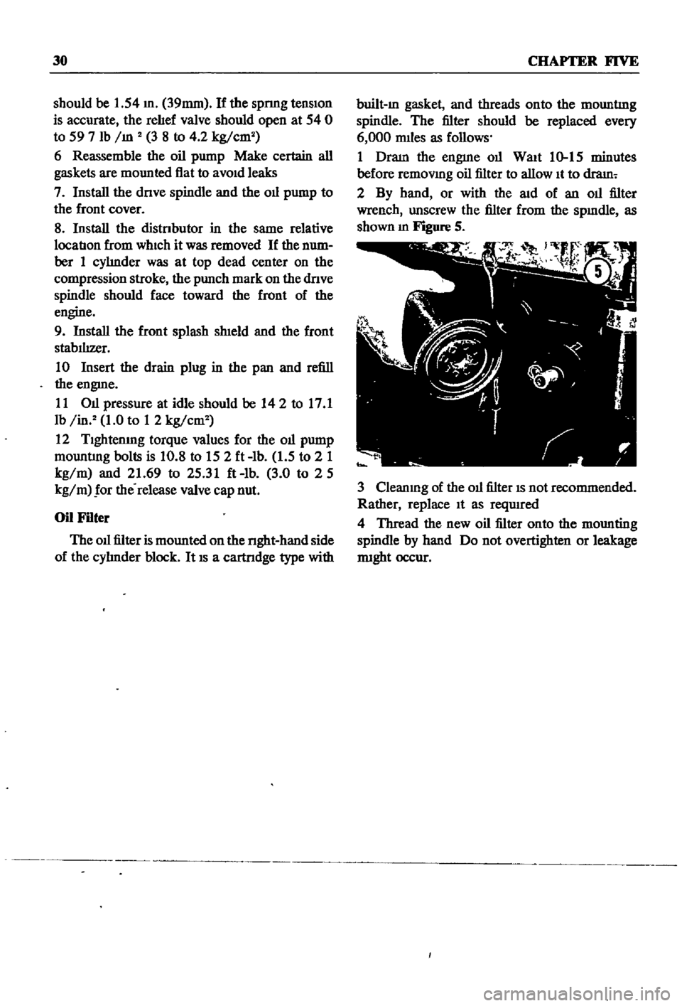
or
with
the
aid
of
an
oil
filter
wrench
unscrew
the
filter
from
the
spmdle
as
shown
m
Figure
S
3
Cleanmg
of
the
oil
filter
IS
not
recommended
Rather
replace
It
as
reqUIred
4
Thread
the
new
oil
filter
onto
the
mounting
spindle
by
hand
Do
not
overtighten
or
leakage
nught
occur
Page 58 of 252

ENGINE
53
the
mam
beanng
cap
and
the
cyhnder
block
beanng
recess
and
tighten
the
cap
bolts
to
the
proper
torque
WIth
a
torque
wrench
Tig
temng
torque
Main
bearings
506
to
57
8
It
Ib
70to80kg
m
195
to
23
9
It
Ib
27
to3
3
kg
m
Rod
beanngs
9
Loosen
the
cap
bolt
on
one
Side
and
measure
the
clearance
Figure
53
between
the
cap
and
block
Side
Clearance
should
be
WIthm
the
fol
lowmg
specmcatIons
Mam
beanngs
0
through
o
0024
m
0
to
0
06mm
rod
beanngs
00012
through
0
0032
m
0
030
to
0
0024mm
Weight
@
10
If
beanng
crush
IS
not
m
tolerance
replace
the
beanngs
Crankshaft
and
Camshaft
Sprockets
1
Check
for
damaged
teeth
Replace
sprocket
1f
necessary
2
Install
the
camshaft
sprocket
and
check
for
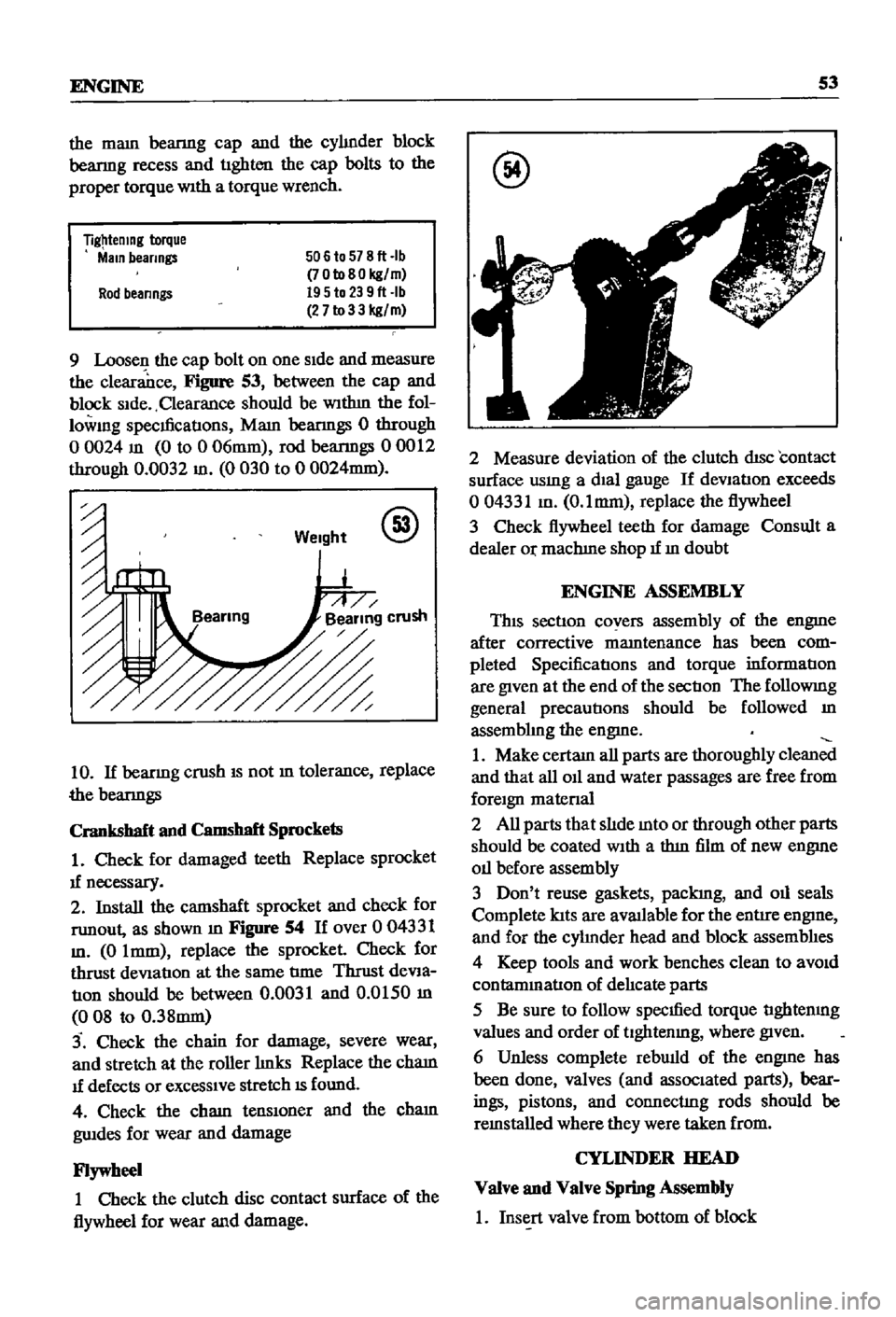
runout
as
shown
m
Figure
54
If
over
0
04331
m
0
Imm
replace
the
sprocket
Check
for
thrust
deViation
at
the
same
tIme
Thrust
deVia
tIOn
should
be
between
0
0031
and
0
0150
m
008
to
0
38mm
3
Check
the
chain
for
damage
severe
wear
and
stretch
at
the
roller
hnks
Replace
the
cham
1f
defects
or
exceSSIve
stretch
IS
found
4
Check
the
cham
tenslOner
and
the
cham
gwdes
for
wear
and
damage
Flywheel
1
Check
the
clutch
disc
contact
surface
of
the
flywheel
for
wear
and
damage
@
2
Measure
deviation
of
the
clutch
disc
contact
surface
usmg
a
dial
gauge
If
deVIation
exceeds
004331
m
O
lmm
replace
the
flywheel
3
Check
flywheel
teeth
for
damage
Consult
a
dealer
Or
machIne
shop
1f
m
doubt
ENGINE
ASSEMBLY
This
section
covers
assembly
of
the
engme
after
corrective
mamtenance
has
been
com
pleted
SpecificatIons
and
torque
informatIon
are
given
at
the
end
of
the
sectIon
The
followmg
general
precautions
should
be
followed
m
assembhng
the
engme
1
Make
certam
all
parts
are
thoroughly
clean
and
that
all
011
and
water
passages
are
free
from
foreign
matenal
2
All
parts
that
slIde
mto
or
through
other
parts
should
be
coated
With
a
thm
film
of
new
engme
011
before
assembly
3
Don
t
reuse
gaskets
packIng
and
011
seals
Complete
lats
are
aVlUlable
for
the
entire
engme
and
for
the
cyhnder
head
and
block
assemblIes
4
Keep
tools
and
work
benches
clean
to
aVOid
contammatlon
of
delIcate
parts
5
Be
sure
to
follow
specmed
torque
tIghtenmg
values
and
order
of
tlghtenmg
where
given
6
Unless
complete
rebwld
of
the
engme
has
been
done
valves
and
associated
parts
bear
ings
pistons
and
connectIng
rods
should
be
remstalled
where
they
were
taken
from
CYLINDER
HEAD
Valve
and
Valve
Spring
Assembly
1
Insert
valve
from
bottom
of
block
Page 59 of 252

54
CHAP1ER
SIX
2
Set
the
valve
spnng
seat
m
position
on
the
top
of
the
block
and
over
the
valve
stem
3
Place
the
oil
seal
over
the
valve
stem
4
Place
the
mner
and
outer
valve
spnngs
over
the
valve
stem
S
Place
the
spnng
retamer
over
the
springs
compress
spnngs
With
spring
compressor
Figure
55
and
mstall
valve
collets
around
valve
stem
so
that
they
lock
onto
stem
6
Release
spnng
compressor
If
collets
are
firm
ly
locked
onto
the
groove
m
the
valve
stem
assembly
IS
complete
7
Install
the
rocker
guIde
on
top
of
the
valve
stem
when
assemblmg
the
rocker
pivot
assembly
VaIve
Rocker
Pivot
Assembly
1
Thread
lock
nut
onto
valve
rocker
pivOt
and
place
rocker
retaIner
over
the
valve
rocker
pivOt
2
Thread
the
above
assembly
mto
the
rocker
bushIng
protrudIng
from
the
head
Camshaft
Assembly
1
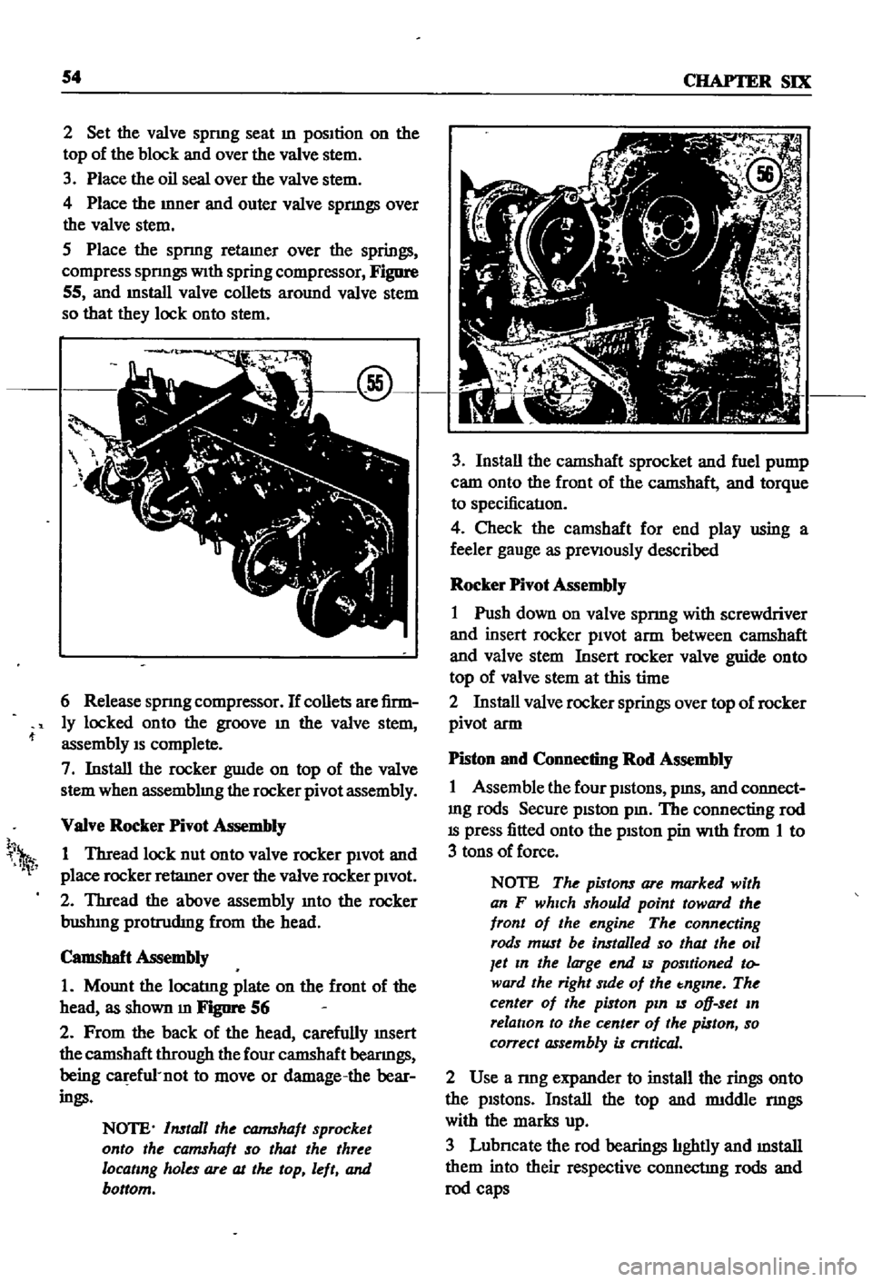
Mount
the
locatIng
plate
on
the
front
of
the
head
as
shown
m
FJgIlI
1
56
2
From
the
back
of
the
head
carefully
InSert
the
camshaft
through
the
four
camshaft
beanngs
being
ca
efu1
not
to
move
or
damage
the
bear
ings
NOTE
Install
the
CQJ7IShaft
sprocket
onto
the
camshaft
so
that
the
three
locating
holes
are
at
the
top
left
and
bottom
h
1
3
Install
the
camshaft
sprocket
and
fuel
pump
cam
onto
the
front
of
the
camshaft
and
torque
to
specificatIon
4
Check
the
camshaft
for
end
play
using
a
feeler
gauge
as
preViously
described
Rocker
Pivot
Assembly
1
Push
down
on
valve
spnng
with
screwdriver
and
insert
rocker
piVOt
arm
between
camshaft
and
valve
stem
Insert
rocker
valve
guide
onto
top
of
valve
stem
at
this
time
2
Install
valve
rocker
springs
over
top
of
rocker
pivot
arm
Piston
and
Connecting
Rod
Assembly
1
Assemble
the
four
pistons
pms
and
connect
mg
rods
Secure
piston
pm
The
connecting
rod
IS
press
fitted
onto
the
pISton
pin
With
from
1
to
3
tons
of
force
NOTE
The
pistons
are
marked
with
an
F
which
should
point
toward
the
front
of
the
engine
The
connecting
rods
must
be
installed
so
that
the
011
Jet
In
the
large
end
IS
positioned
to
ward
the
right
Side
of
the
tnglne
The
center
of
the
piston
pin
IS
oD
set
In
relation
to
the
center
of
the
piston
so
correct
assembly
is
cntical
2
Use
a
nng
expander
to
install
the
rings
onto
the
pistons
Install
the
top
and
rmddle
nngs
with
the
marks
up
3
Lubncate
the
rod
bearings
hghtly
and
mstall
them
into
their
respective
connectIng
rods
and
rod
caps
Page 60 of 252

ENGINE
55
Cylinder
Block
Assembly
1
PositIon
all
crankshaft
parts
on
a
work
bench
ThIS
mcludes
the
crankshaft
main
beanngs
rear
011
seal
woodruff
keys
crankshaft
gear
011
pump
gear
011
thrower
bolts
and
bearing
caps
Figure
57
shows
the
arrangement
@
2
Insert
maIO
beanngs
mto
appropnate
cy1m
der
block
holders
NOTE
The
center
No
3
beanng
IS
the
only
flanged
type
of
thrust
bear
Ing
Bearings
No
2
and
No
4
are
Identical
No
1
and
No
5
Jaring
ap
pear
identical
but
No
1
as
an
011
hole
All
bearings
except
No
1
are
Interchangeable
as
to
upper
and
lower
half
3
LIghtly
lubncate
the
crankshaft
and
beanng
matmg
surfaces
then
mstall
beanngs
10
mam
beanng
caps
4
Install
the
crankshaft
5
Install
mam
beanng
caps
over
crankshaft
msert
mam
cap
bolts
and
tighten
hghtly
The
mam
beanng
caps
have
an
arrow
marked
on
each
one
These
must
pomt
to
the
front
of
the
engme
6
Gently
move
the
crankshaft
10
an
aXIal
drrec
don
toward
the
front
of
the
engme
to
venfy
that
the
mam
beanng
caps
are
properly
alIgned
and
seated
7
Use
a
torque
wrench
to
tighten
the
cap
bolts
to
the
hmlts
speCIfied
The
t1ghtenmg
operatIon
should
be
done
gradually
10
three
or
four
sep
arate
stages
starting
10
the
center
and
workmg
outward
to
each
end
8
Rotate
the
crankshaft
to
make
certain
it
isn
t
bmding
9
Use
a
feeler
gauge
to
check
the
end
play
at
the
center
No
3
beanng
Figure
58
10
Install
the
SIde
oll
seals
into
the
rear
mam
cap
and
cy1mder
block
as
shown
10
Figure
59
@
11
Install
the
rear
011
seal
WIth
Datsun
tool
ST49370000
or
equIvalent
12
Install
the
rear
end
plate
13
Install
the
flywheel
WIth
proper
bolts
and
lock
washers
and
torque
as
specified