1968 DATSUN 510 alternator
[x] Cancel search: alternatorPage 4 of 252
II
CHAPTER
SIX
ENGINE
Cylmder
block
Crankshaft
PistOns
and
connectmg
rods
Cyhnder
head
Camshaft
Valve
mechamsm
Camshaft
dnve
Mamfolds
011
pump
Fuel
pump
Carburetor
Emission
control
devIces
Engme
removal
Engme
dISassembly
Pistons
and
connectmg
rods
Cyhnder
head
Engme
mspectIon
and
replllr
Engme
reassembly
Service
data
and
speCifications
CHAPTER
SEVEN
FUEL
SYSTEM
Air
cleaner
Fuel
strlllner
Fuel
pump
Carburetor
Fuel
tank
1
CHAPTER
EIGHT
COOLING
SYSTEM
DescnptIon
Water
pump
Fan
clutch
Thermostat
Radiator
CHAPTER
NINE
ENGINE
ELECTRICAL
SYSTEM
Starter
Overrunmng
clutch
assembly
ChargIng
ClrcUlt
Alternator
Alternator
output
Voltage
regulator
DIstrIbutor
Condenser
Igrntlon
cod
SpeCifications
Spark
plugs
CHAPTER
TEN
EMISSION
CONTROL
SYSTEM
Exhaust
emiSSIOn
control
Crankcase
emission
control
Air
mJectlon
system
Engme
modifications
Evaporative
emiSSion
control
Exhaust
system
CHAPTER
ELEVEN
CLUTCH
TRANSMISSION
AND
DRIVESHAFT
Clutch
TransmissIon
Master
cyhnder
TransmissIon
data
and
speCIfications
Operating
cyhnder
Dnveshaft
Withdrawal
lever
adjustment
Dnveshaft
data
and
speCIfications
Clutch
system
bleedmg
Automatic
transmIssIon
checks
Clutch
data
and
speCIfications
31
62
84
91
114
127
Page 12 of 252

PERIODIC
MAINTENANCE
7
Table
1
ENGINE
LUBRICATION
AND
MAINTENANCE
FREQUENCY
EVERY
E
E
E
E
E
E
E
Eo
00
00
00
00
00
00
00
gq
00
00
00
NO
t
r61li
0
CD
Check
engine
011
level
top
up
If
required
X
Change
engine
011
X
Lubricate
carburetor
hnkage
X
Lubricate
distributor
rotor
shaft
and
ann
shaft
X
Apply
grease
to
distributor
cam
heel
X
Check
radiator
coolant
level
X
Change
radIator
coolant
X
Change
radiator
coolant
additive
X
Check
battery
electrolyte
level
X
Check
specific
gravity
of
battery
X
Check
engine
starting
exhaust
color
X
Tighten
cyhnder
head
manifolds
and
pipe
flanges
X
Adjust
valve
clearance
X
Check
Ignition
timing
X
Tighten
carburetor
fittings
X
Check
fan
belt
tension
X
Check
for
011
pan
leakage
X
Tighten
engine
mounts
X
Check
fuel
strainer
X
Replace
fuel
strainer
X
Check
for
fuel
leaks
X
Replace
011
filter
X
Check
spark
plugs
X
Replace
spark
plugs
X
Check
dlstnbutor
cap
rotor
and
POints
X
Adjust
engine
Idle
speed
X
Check
air
cleaner
fittings
X
Clean
011
filler
cap
X
Clean
battery
cables
and
terminals
X
Check
alternator
and
voltage
regulator
function
X
Check
starter
motor
function
X
Replace
aIr
cleaner
element
X
Check
fuel
pump
function
X
Check
cyhnder
compressIon
X
Clean
carburetor
Jets
and
float
chamber
X
Check
dlstnbutor
condenser
X
Check
crankcase
ventilation
control
valve
X
Page 17 of 252

12
CHAPTER
THREE
13
IMPROPER
IDLE
MIXTURE
Roats
slowly
between
13
17
14
SMALl
SPARK
GAP
or
DEFECTIVE
POINTS
Slight
float
between
14
16
ignItIOn
switch
If
the
starter
still
fails
to
crank
properly
remove
the
starter
and
test
it
2
Starter
turns
but
does
not
engage
with
engine
This
trouble
is
usually
a
defective
pInion
or
sole
noid
shlfting
fork
It
may
also
be
that
the
teeth
on
the
pInion
flywheel
ring
gear
or
both
are
worn
down
too
far
to
engage
properly
3
Starter
engages
but
will
not
dISengage
when
IgmtlOn
switch
IS
released
TIns
trouble
is
usually
caused
by
a
sticking
sole
nOid
but
occasionally
the
pmlOn
can
jam
on
the
flywheel
With
manual
transmissions
the
pinion
can
be
temporanly
freed
by
rockmg
the
car
in
high
gear
Naturally
this
IS
not
poSSible
in
auto
matics
the
starter
must
be
removed
4
Loud
grinding
noISes
when
starter
runs
TIns
usually
means
the
teeth
on
the
pinion
and
or
flywheel
are
not
meshing
properly
It
may
also
mean
the
over
running
clutch
IS
broken
In
the
first
case
remove
the
starter
and
examine
the
gear
teeth
In
the
latter
remove
the
starter
and
replace
the
pmion
dnve
assembly
CHARGING
SYSTEM
Charging
system
troubles
may
be
in
the
alter
nator
voltage
regulator
or
fan
belt
The
follow
ing
symptoms
are
typical
1
Alternator
warning
lamp
does
not
come
on
when
IgmtlOn
is
turned
on
This
may
indicate
a
defective
ignition
switch
battery
voltage
regulator
or
lamp
Frrst
try
to
15
HEAD
GASKET
LEAK
Roats
between
5
19
16
RESTRICTm
EXHAUST
SYSTEM
Normal
when
first
started
Drops
to
0
as
rpm
Increases
May
eventually
rrse
to
about
16
start
the
car
If
it
doesn
t
start
check
the
igllltlon
sWitch
and
battery
If
the
car
starts
find
the
voltage
regulator
and
disconnect
the
wlute
red
Wire
this
is
the
lamp
wire
Ground
the
wire
If
the
lamp
hghts
the
voltage
regulator
is
defective
not
properly
grounded
try
tightening
the
mounting
screws
or
the
alternator
brushes
are
not
contactmg
the
commutator
If
the
lamp
does
not
light
when
the
wire
IS
grounded
the
lamp
is
probably
burned
out
replace
It
2
Alternator
warning
lamp
comes
on
and
stays
on
This
usually
mdicates
that
no
chargmg
is
takmg
place
Frrst
check
the
fan
belt
tension
and
adlust
if
necessary
Check
the
battery
condition
with
the
hydrometer
and
check
all
electrical
connec
tions
m
the
chargmg
system
Fmally
isolate
the
trouble
to
the
alternator
or
voltage
regulator
3
Alternator
warmng
lamp
flashes
erratically
This
usually
indicates
the
chargmg
system
is
workmg
intermittently
Check
the
fan
belt
ten
sion
and
all
electncal
connections
m
the
charg
ing
system
Check
alternator
brushes
and
cODlh
tlon
of
the
commutator
4
Baltery
reqUires
frequent
additiOns
of
water
or
lamps
require
frequent
replacement
The
alternator
IS
probably
overchargmg
the
bat
tery
The
voltage
regulator
is
probably
faulty
check
it
using
the
procedures
given
in
Chaper
Nme
5
ExceSSive
noISe
from
he
alternator
Check
for
loose
alternator
mountmg
The
Page 18 of 252

TROUBLESHOOTING
13
trouble
may
also
be
worn
bearings
Remove
the
alternator
and
repair
ENGINE
These
procedures
assume
the
starter
cranks
the
engme
over
normally
If
not
refer
to
Starter
section
m
this
chapter
1
Engme
won
t
start
Could
be
caused
by
the
IgOltlon
or
fuel
problems
First
determine
If
high
voltage
to
spark
plug
occurs
To
do
thiS
dISconnect
one
of
the
spark
plug
wires
Hold
the
exposed
wrre
termlOal
y
to
Y2
lOch
from
ground
any
metal
in
engine
com
partment
With
an
msulated
screwdriver
Crank
the
engme
over
If
sparks
do
not
Jump
to
ground
or
the
sparks
are
very
weak
the
trouble
may
be
10
the
IgnitIOn
system
See
Ignition
System
Trou
bleshootmg
to
further
check
If
sparks
occur
properly
the
trouble
may
be
10
the
fuel
system
See
Fuel
System
Troubleshootmg
2
Engme
misses
steadily
Remove
one
spark
plug
wrre
at
a
tune
and
ground
the
wrre
If
engme
mISs
increases
that
cyhnder
was
work
109
properly
Reconnect
the
wire
and
check
the
others
When
a
wire
IS
dIs
connected
and
engme
miss
remams
the
same
that
cylinder
IS
not
finng
Check
spark
as
descnbed
10
Step
1
If
no
spark
occurs
for
one
cyhnder
only
check
dlStnbutor
cap
wrre
and
spark
plug
If
spark
occurs
prop
erly
check
compressIOn
and
mtake
maOlfold
vacuum
to
ISolate
the
trouble
3
Engme
misses
erratlcally
at
all
speeds
Interrmttent
trouble
can
be
difficult
to
find
It
could
be
ill
the
Ignition
system
exhaust
system
or
fuel
system
Follow
troubleshooting
proce
dures
for
these
systems
carefully
to
isolate
the
trouble
4
Engme
misses
at
Idle
only
Trouble
could
exist
anywhere
ill
IgOltlon
system
Follow
Ignition
TroubleshootlOg
procedure
care
fully
Trouble
could
also
eXist
10
the
carburetor
Idle
crrcult
Check
Idle
mIXture
adjustment
and
check
for
restnctions
m
the
idle
crrcUlt
5
Engme
misses
at
high
speed
only
Problems
could
be
ill
the
fuel
or
IgOltlon
systems
heck
accelerator
pump
operation
fuel
pump
dehvery
fuel
hnes
etc
as
descnbed
under
Fuel
System
Troubleshootillg
Also
check
spark
plugs
and
wrres
6
Low
performance
at
all
speeds
poor
acceleratIOn
Trouble
usually
ill
IgOltlon
or
fuel
system
Check
each
With
the
appropnate
troubleshooting
pro
cedure
7
ExceSSive
fuel
consumptIOn
Could
be
caused
by
a
Wide
variety
of
seemmgly
unrelated
factors
Check
for
clutch
shppage
brake
drag
defective
wheel
beanngs
or
poor
front
end
alignment
Check
IgOltlOn
system
and
fuel
system
8
011
pressure
lamp
does
not
light
when
IgmtlOn
switch
IS
on
Check
the
alternator
warning
lamp
If
it
ISn
t
on
either
go
to
Step
1
Chargmg
System
Trouble
shootlOg
If
only
the
oil
pressure
lamp
IS
off
open
the
englOe
compartment
hd
and
locate
the
oil
pressure
sender
on
the
block
near
the
oil
filter
Make
sure
the
wrre
is
connected
to
the
sender
and
makmg
good
contact
Pull
the
wrre
off
and
ground
it
If
the
lamp
hghts
replace
the
sender
If
the
lamp
does
not
light
replace
the
lamp
9
011
pressure
lamp
lights
or
flickers
when
engme
IS
runmng
Indicates
low
or
complete
loss
of
oil
pressure
Stop
the
englOe
unmedmtely
coast
to
a
stop
With
the
clutch
dISengaged
Tlus
may
simply
be
caused
by
a
low
oil
level
or
an
overheatmg
en
glOe
Check
the
oil
level
and
fan
belt
tensIOn
Check
for
a
shorted
oil
pressure
sender
with
an
ohmmeter
or
a
contlOulty
tester
Remove
and
clean
the
oil
dipstick
and
check
oil
level
and
condition
RepleOlsh
or
replace
the
oil
as
re
qurred
Listen
for
unusual
nOISes
mdlcatmg
dam
aged
beanngs
etc
Do
not
re
start
the
engine
until
you
know
why
the
hght
went
on
and
are
sure
that
the
problem
has
been
corrected
IGNITION
SYSTEM
This
procedure
assumes
the
battery
IS
ill
good
enough
condition
to
crank
the
engme
at
a
normal
rate
Page 31 of 252
26
CHAPTER
FOUR
2
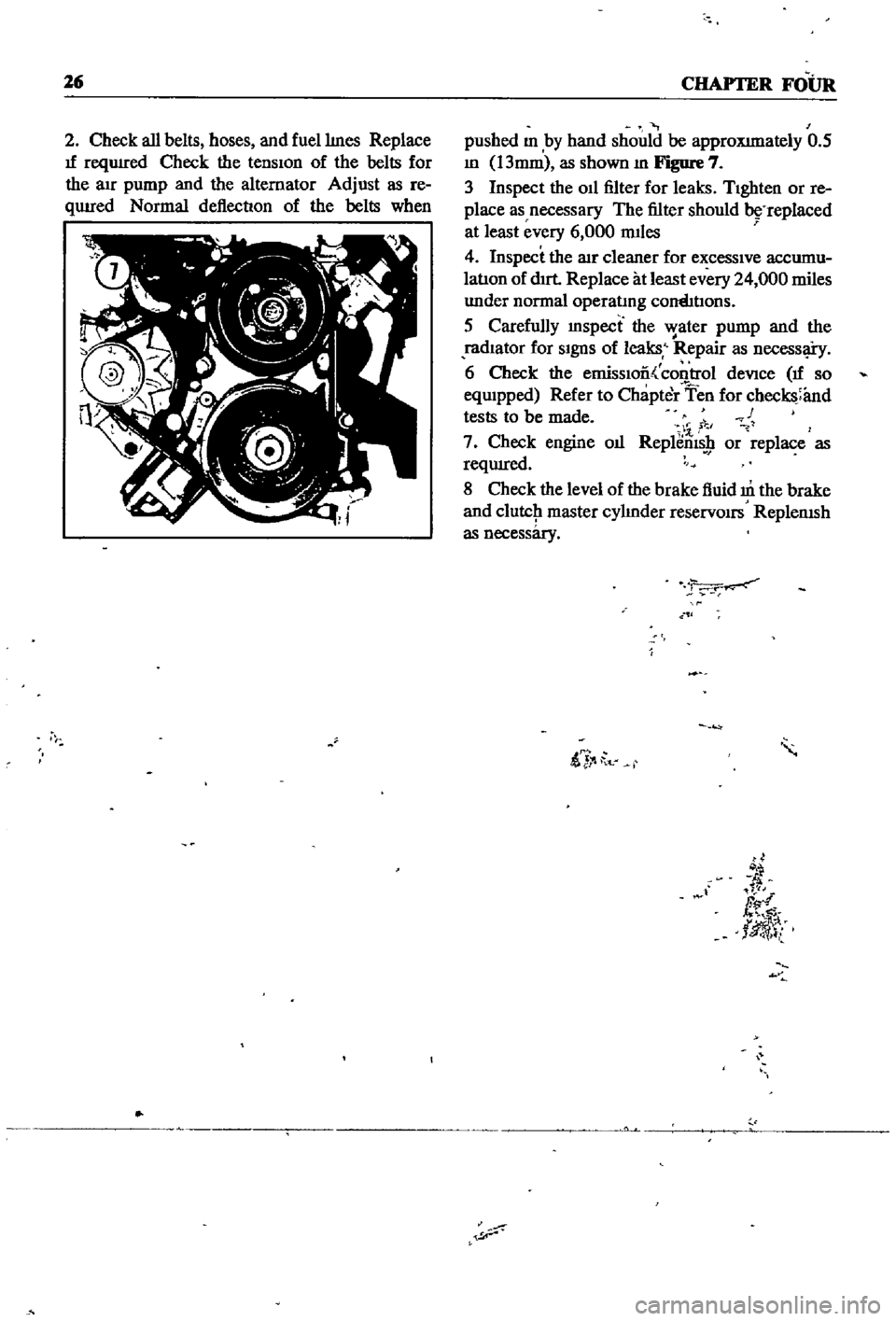
Check
all
belts
hoses
and
fuellmes
Replace
If
reqUIred
Check
the
tensIon
of
the
belts
for
the
au
pump
and
the
alternator
Adjust
as
re
qUIred
Normal
deflection
of
the
belts
when
pushed
m
by
hand
should
be
approXImately
0
5
m
13mm
as
shown
m
Figure
7
3
Inspect
the
011
filter
for
leaks
TIghten
or
re
place
as
necessary
The
filter
should
replaced
at
least
every
6
000
mIles
4
Inspect
the
lIlr
cleaner
for
excessIve
accumu
latIon
of
dIrt
Replace
at
least
every
24
000
miles
under
normal
operatmg
cornhtIons
5
Carefully
mspect
the
water
pump
and
the
radIator
for
SIgnS
of
leaks
Repair
as
necessl
i
y
6
Check
the
emissIoo
control
deVice
If
so
eqwpped
Refer
to
Chapter
Ten
for
checks
and
tests
to
be
made
c
1
7
Check
engine
oIl
Replems
9
or
replace
as
reqUIred
8
Check
the
level
of
the
brake
fluid
m
the
brake
and
clutcJ1
master
cylmder
reservOirs
ReplenISh
as
necessary
ii
t
d
fl
tlJ
l
Page 36 of 252
CHAPTER
SIX
ENGINE
Datsun
510
and
521
veJucles
use
the
L16
engme
Over
the
years
the
deSign
remamed
essentIally
the
same
with
nunor
changes
made
to
accommodate
drlIerent
elIDSSlon
control
de
VIces
The
Ll6
IS
a
four
cylmder
overhead
cam
shaft
engme
With
a
97
3
cubic
mch
1595cc
dISplacement
Cylmder
bore
IS
3
2677
in
83mm
stroke
IS
2
9016
m
73
7mm
Output
IS
96
horsepower
1972
mode1s
92
horse
power
at
5
600
rpm
Compression
ratIo
is
8
5
to
1
Equipment
includes
a
single
two
barrel
Hltaclu
carburetor
an
HItachi
alternator
an
HItachi
starter
motor
and
either
a
smgle
point
or
dual
pomt
distnbutor
Figure
1
next
page
IS
an
overall
view
of
the
engme
Figure
2
next
page
is
a
sectIonal
view
The
following
para
graphs
describe
and
illustrate
the
major
com
ponents
of
the
engine
and
provide
detaIled
InStructIons
on
the
removal
disassembly
inspec
tIon
reparr
and
reassembly
of
the
engine
CYLINDER
BLOCK
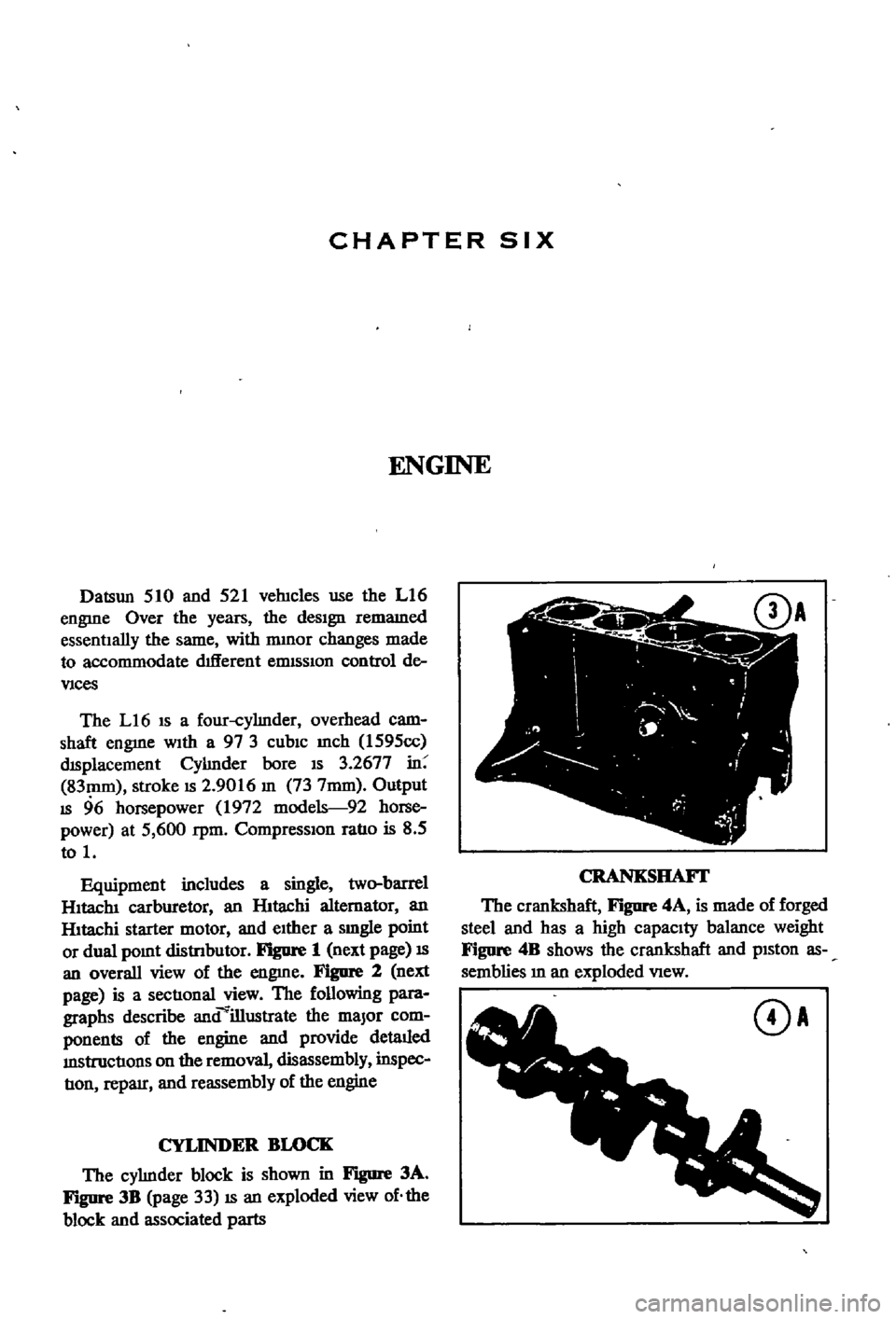
The
cylmder
block
is
shown
in
Figure
3A
Figure
3B
page
33
IS
an
exploded
view
of
the
block
and
associated
parts
CRANKSHAFI
The
crankshaft
F
JgUre
4A
is
made
of
forged
steel
and
has
a
high
capacity
balance
weight
Figure
4B
shows
the
crankshaft
and
pISton
as
semblies
m
an
exploded
VIew
DA
Page 43 of 252
38
CHAPTER
SIX
EMISSION
CONTROL
DEVICES
All
Datsuns
have
a
sealed
type
of
crankcase
emISSion
control
device
and
an
exhaust
emISsion
control
deVice
Models
sold
m
Cahfornla
smce
1970
also
have
an
evaporative
emisSion
control
deVice
An
rmportant
part
of
the
exhaust
control
device
is
the
air
pump
located
at
the
bottom
left
hand
side
of
the
engme
It
IS
dnven
by
a
belt
off
of
the
crankshaft
pulley
and
supphes
air
to
the
exhaust
system
In
1972
an
electric
blower
in
corporated
m
the
air
cleaner
replaced
the
mechanical
pumI
ENGINE
REMOVAL
Expenence
has
shown
It
IS
easier
to
remove
the
engine
and
the
transmission
as
a
smgle
UnIt
than
to
remove
the
engme
alone
Once
the
en
gine
and
transmiSSIon
are
out
of
the
vehIcle
the
tranSmIssion
can
be
detached
from
the
engme
To
remove
the
engme
transmISsion
proceed
as
follows
1
Scribe
ahgnment
marks
on
the
hood
around
the
hmges
ThIS
will
make
remstallatlon
eaSIer
2
Remove
the
two
bolts
that
secure
each
hInge
and
remove
the
hood
It
is
not
necessary
to
re
move
the
hood
support
from
the
engme
firewall
3
DISconnect
the
lower
radIator
hose
from
the
right
hand
SIde
of
the
engine
and
at
the
bottom
of
the
radIator
ThIS
will
pernnt
coolant
to
dram
from
the
engme
and
the
radIator
4
Remove
the
draIn
plugs
from
the
engine
pan
and
translIDSsIon
and
completely
dram
lubn
cants
Into
suitable
contamers
5
DISconnect
the
battery
cables
from
the
bat
tery
loosen
the
two
hold
down
clamps
and
re
move
the
battery
NOTE
The
location
and
number
of
hoses
to
be
removed
from
the
air
cleaner
varies
from
model
to
model
It
IS
normally
easier
to
remove
the
hoses
from
the
sources
rather
than
try
to
dISconnect
them
from
yndemeath
the
air
cleaner
The
1972
model
Will
requlre
dlsconnectlOn
of
the
electrica1
cirCUit
In
the
air
cleaner
system
wing
nut
from
the
top
of
the
air
cleaner
and
remove
the
aIr
cleaner
7
DIsconnect
the
upper
radiator
hose
from
the
radiator
and
the
thermostat
housmg
Remove
the
hose
8
Disconnect
the
two
heater
hoses
from
the
nght
hand
side
of
the
engme
TIe
these
bac
so
they
won
t
interfere
with
removal
of
the
engme
9
Remove
the
radIator
grille
by
unscrewing
all
mountmg
screws
10
Remove
the
four
mounting
screws
holding
the
fan
shield
to
the
backside
of
the
radiator
11
Remove
the
four
mountmg
bolts
holdIng
the
radiator
In
place
In
automatic
tranSmISsion
models
dISconnect
the
two
transnnsslOn
oIl
cooler
lInes
from
the
bottom
of
the
radiator
Pull
the
radiator
straight
up
to
remove
Remove
the
fan
shield
12
Loosen
the
adjustment
and
mounting
bolts
from
the
retamIng
brackets
on
the
alternator
and
air
pump
If
so
eqwpped
The
alternator
is
lo
cated
at
the
bottom
nght
hand
Side
of
the
engme
and
the
air
pump
on
the
lower
left
hand
Side
13
Loosen
tenSIon
on
the
two
dnve
belts
re
move
the
belts
from
the
alternator
and
air
pump
and
then
from
the
fan
pulleys
14
Remove
the
bolts
holdIng
the
fan
and
pulley
to
the
water
pump
assembly
and
remove
the
fan
and
pulley
15
DISconnect
the
fuel
hne
from
the
fuel
pump
16
DIsco
ect
accelerator
control
linkage
and
choke
WIre
at
the
carburetor
17
Disconnect
the
wiring
from
the
starter
motor
alternator
Ignition
coIl
oIl
pressure
switch
and
temperature
transmItting
unit
NOTE
The
following
steps
are
per
formed
from
under
the
car
lack
up
the
front
of
the
car
and
position
stands
under
the
front
support
points
to
proVide
working
room
under
the
vehicle
WARNING
Never
climb
under
a
vehicle
that
is
supported
by
the
lack
only
If
stands
are
not
avflllable
sturdy
wooden
blocks
can
be
U3ed
6
Disconnect
all
hoses
that
lead
to
the
air
cleaner
remove
two
bolts
that
hold
the
air
cleaner
to
its
mountmg
bracket
unscrew
the
18
Remove
two
bolts
holdIng
the
clutch
operat
Ing
cylInder
to
the
flywheel
hOUSIng
shown
m
Page 45 of 252
40
CHAPTER
SIX
be
removed
Hoist
the
engme
off
Its
mounts
and
adjust
the
cham
or
cable
to
tIlt
the
engme
as
shown
in
the
illustration
ContInue
to
raIse
gradually
31
Once
the
engine
and
transmission
are
clear
of
the
vehIcle
lower
them
to
a
swtable
support
or
stand
and
dIsconnect
the
hOISt
32
The
transmISSIon
can
now
be
freed
by
re
movmg
the
bolts
holdIng
the
clutch
assembly
to
the
flywheel
housing
and
movmg
the
clutch
assembly
back
to
dIsengage
the
dnve
shaft
splmes
33
Witlltlie
engIne
removed
carefiillyinspect
the
mountIng
Insulators
for
SIgnS
of
damage
or
detenoratIon
Replace
them
1f
necessary
ENGINE
DISASSEMBLY
ThIS
sectIon
covers
dIsassembly
of
the
engine
once
It
has
been
removed
from
the
vehIcle
All
steps
would
be
followed
for
a
complete
engme
overhaul
But
smce
many
of
the
procedures
can
be
done
WIthout
removing
the
engIne
from
the
velucle
a
complete
course
of
actIon
should
be
decided
on
before
needless
removal
and
ms
assembly
Mount
the
engme
on
a
stand
or
other
sUItable
work
surface
before
msassembly
Thoroughly
clean
the
extenor
WIth
steam
or
solvent
CAUTION
Remove
the
alternator
starter
motor
carburetor
and
dIStributor
from
the
engine
before
cleaning
to
prevent
damage
Once
clean
mspect
the
engme
for
SIgnS
of
damage
or
mlssmg
parts
cracks
or
accumulated
rust
on
the
block
especIally
around
the
soft
plugs
cracks
In
the
clutch
housing
and
dents
or
cracks
In
the
oil
pan
DISassemble
as
follows
Alternator
Removal
1
Figure
14
shows
the
positIon
of
the
alternator
on
the
engme
and
a
VIew
of
the
alternator
mountIng
parts
Remove
the
two
bolts
lock
washers
and
shmls
holding
the
alternator
to
the
adjustIng
bar
and
the
adjustIng
bar
to
the
engme
block
2
Remove
the
two
bolts
and
lockwashers
hold
ing
the
alternator
to
lower
mounting
bracket
3
Remove
the
alternator
and
mountmg
brack
ets
Starter
Motor
Removal
1
Remove
two
mountIng
bolts
and
lockwashers
holdmg
starter
motor
to
clutch
housmg
2
Pull
starter
assembly
toward
front
of
engme
and
remove
Distributor
Removal
1
Scnbe
ahgnment
marks
on
the
mstrlbutor
shaft
tl
ie
ihsthDutor
mountmg
oracket
anihlfe
front
cover
so
that
the
dIStnbutor
can
be
re
placed
accurately
later
2
Remove
two
bolts
and
lockwashers
holdIng
the
dlstnbutor
mountmg
housmg
to
the
front
cover
3
Pull
up
on
the
dlstnbutor
and
remove
it
as
a
unit
Carburetor
Removal
1
Remove
the
four
nuts
and
lockwashers
join
mg
the
carburetor
and
mtake
manifold
then
remove
carburetor
Oil
Pump
Removal
1
Remove
the
four
mountIng
bolts
and
lock
washers
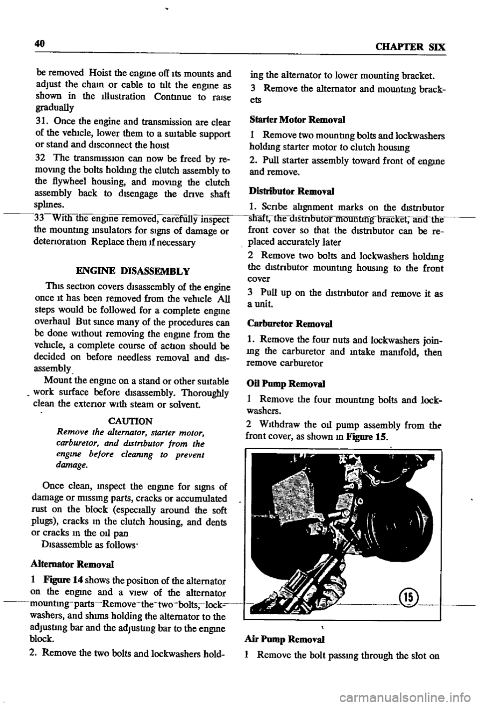
2
WIthdraw
the
011
pump
assembly
from
tht
front
cover
as
shown
m
Figure
15
@
Air
Pump
Removal
1
Remove
the
bolt
passmg
through
the
slot
on