1968 DATSUN 510 diagram
[x] Cancel search: diagramPage 5 of 252
CHAPTER
TWELVE
DIFFERENTIAL
REAR
AXLE
AND
REAR
SUSPENSION
149
DIfferentIal
Rear
axle
and
suspension
Codspnng
Shock
absorber
Rear
suspensIOn
arm
Rear
axle
shaft
Wheel
beanngs
Seals
Rear
spnng
Axle
case
SpecificatIons
CHAPTER
THIRTEEN
FRONT
AXLE
FRONT
SUSPENSION
AND
STEERING
168
Wheel
hub
and
bearmg
StabilIzer
TenSion
rod
Spnng
and
strut
assembly
Transverse
lInk
Lower
ball
Jomt
Front
suspension
adjustment
Wheel
alignment
Posture
adJustment
Steenng
system
SpeCificatIons
CHAPTER
FOURTEEN
BRAKES
187
Brake
pedal
Master
cylInder
Front
diSC
brakes
Rear
brakes
Front
drum
brakes
Wheel
cylInders
Brake
system
bleedIng
Handbrake
Service
data
and
speCificatIons
CHAPTER
FIFTEEN
BODY
ELECTRICAL
SYSTEM
Wmng
SWitches
and
fuses
Instrument
meters
and
panels
Heater
205
Wmdshleld
wipers
Wmdslueld
washers
Headlamps
WIrIng
diagrams
CHAPTER
SIXTEEN
BODY
223
Front
body
trIm
Bumpers
Hood
lock
control
Doors
Door
locks
and
regulators
Trunk
lId
and
rear
bumper
Seats
Tad
gate
INDEX
235
I
Page 25 of 252

CHAPTER
FOUR
ENGINE
AND
IGNITION
TUNE
UP
For
best
performance
and
economy
care
must
be
taken
in
perfornnng
tune
ups
While
accuracy
is
required
the
task
IS
not
d1flicult
if
the
steps
m
tlus
chapter
are
followed
carefully
Cars
used
pnmarily
m
CIty
stop
and
go
dnv
ing
WIll
reqwre
attention
more
frequently
than
those
used
on
highways
ThIs
is
because
the
engme
does
not
reach
full
operatIng
temperature
ConsequentlY
valves
tend
to
stick
compression
drops
and
engme
operatIon
becomes
rough
A
tune
up
IS
adVISable
every
6
000
miles
or
sooner
dependmg
on
type
of
driving
Every
12
000
nu1es
the
spark
plugs
and
ignitIon
break
er
pomts
should
be
replaced
not
Just
cleaned
and
adjusted
A
mmor
tune
up
consISts
of
checking
battery
condItIon
cleanmg
gapping
or
replacmg
spark
plugs
and
dIstnbutor
breaker
pomts
adjustIng
dIStnbutor
dwell
angle
adjusting
IgnitIon
tun
mg
and
settIng
the
carburetor
Idle
mixture
and
idle
speed
A
major
wne
up
includes
the
above
items
plus
igllltIon
compressIOn
valve
clear
ance
carburetor
emISsion
control
deVIce
and
electncal
checks
and
adjustments
Tune
up
Equipment
Required
The
follOWIng
eqUIpment
IS
required
Chap
ter
Two
provides
a
bnef
descnption
of
the
test
eqwpment
I
Voltmeter
ammeter
and
ohmmeter
2
Hydrometer
3
CompressIOn
tester
4
Vacuum
gauge
s
Dwell
meter
6
Tachometer
7
I
StrobOSCOpIC
tmung
lIght
8
Feeler
gauges
9
Torque
wrench
10
Assorted
hand
tools
Connection
of
Tune
up
Equipment
Follow
the
manufacturer
s
recommendations
for
the
use
of
test
eqwpment
If
pOSSible
Figme
1
IS
a
basiC
schematic
diagram
applicable
to
CD
10
Battery
I
TIm1Illbght
T
8Ier
spa
k
plup
Page 61 of 252
56
CHAPTER
SIX
NOTE
Lubncate
the
cylinder
walls
with
new
engine
oil
prior
to
insertIOn
of
pistOns
Make
certain
that
the
ring
gaps
are
not
In
line
wIth
one
another
Place
the
gaps
180
degrees
from
each
other
and
not
posltloned
either
front
to
back
or
dIrectly
in
line
with
the
piston
pIns
CAUTION
Use
extreme
care
when
Inserting
pzs
tons
so
as
to
avoId
crankshaft
damage
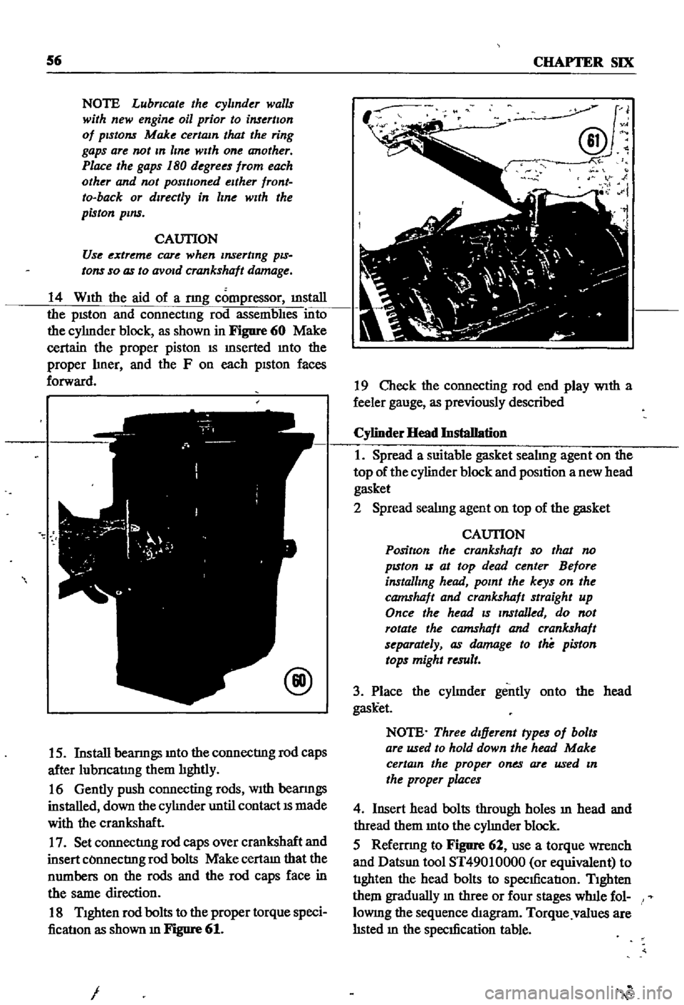
14
With
the
aid
of
a
nng
compressor
illStaIl
the
pISton
and
connectmg
rod
assembhes
into
the
cyhnder
block
as
shown
in
Figure
60
Make
certain
the
proper
piston
IS
mserted
mto
the
proper
hner
and
the
F
on
each
pISton
faces
forward
@
15
Install
beanngs
mto
the
connectIng
rod
caps
after
lubncatmg
them
hghtly
16
Gently
push
connecting
rods
With
beanngs
installed
down
the
cyhnder
until
contact
IS
made
with
the
crankshaft
17
Set
connectIng
rod
caps
over
crankshaft
and
insert
COnnectIng
rod
bolts
Make
certam
that
the
numbers
on
the
rods
and
the
rod
caps
face
in
the
same
direction
18
Tighten
rod
bolts
to
the
proper
torque
speci
ficatIon
as
shown
m
Figure
61
I
J
@v
N
i
19
Check
the
connecting
rod
end
play
With
a
feeler
gauge
as
previously
described
Cylinder
Head
Installation
1
Spread
a
suitable
gasket
seahng
agent
on
the
top
of
the
cylinder
block
and
position
a
new
head
gasket
2
Spread
seahng
agent
on
top
of
the
gasket
CAUTION
PositIon
the
crankshaft
so
that
no
pzston
IS
at
top
dead
center
Before
installing
head
point
the
keys
on
the
camshaft
and
crankshaft
straight
up
Once
the
head
zs
Installed
do
not
rotate
the
camshaft
and
crankshaft
separately
as
damage
to
the
piston
tops
might
result
3
Place
the
cyhnder
gently
onto
the
head
gask
et
NOTE
Three
dIfferent
types
of
bolts
are
used
to
hold
down
the
head
Make
certain
the
proper
ones
are
used
In
the
proper
places
4
Insert
head
bolts
through
holes
ill
head
and
thread
them
mto
the
cyhnder
block
5
Refemng
to
Figure
62
use
a
torque
wrench
and
Datsun
tool
ST49010000
or
equivalent
to
tIghten
the
head
bolts
to
specIficatIon
Tighten
them
gradually
m
three
or
four
stages
wlnle
fol
lOWIng
the
sequence
diagram
Torque
values
are
hsted
m
the
specIfication
table
Page 62 of 252
ENGINE
57
@
L
13
and
L
16
engme
000000
8
4
2
6
10
7
3
1
5
9
o
0
0
0
0
Front
Crankshaft
and
Timing
Chain
Assembly
1
Insert
a
woodruff
key
mto
the
crankshaft
key
way
and
slide
the
crankshaft
sprocket
mto
place
2
Insert
a
woodruff
key
m
the
Illiddle
crank
shaft
keyway
and
slide
the
dIstnbutor
dnve
gear
mto
place
3
FIt
the
oil
thrower
to
the
crankshaft
as
shown
m
Figure
63
NOTE
Make
certam
that
the
crank
shaft
and
camshaft
keys
are
polntlng
upwards
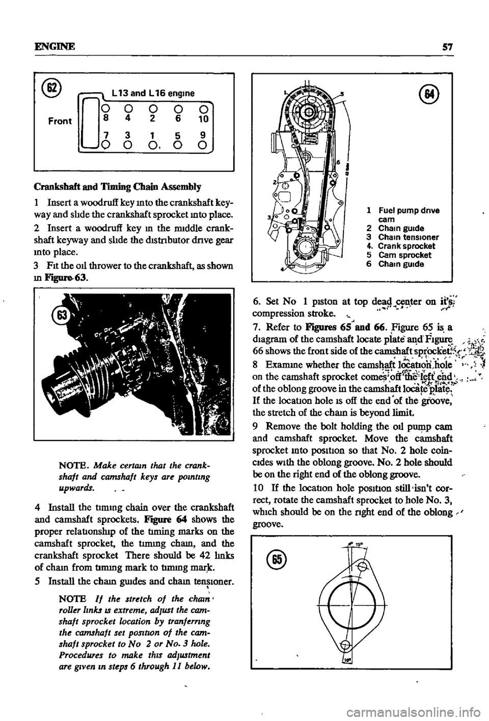
4
Install
the
tmung
chain
over
the
crankshaft
and
camshaft
sprockets
Figure
64
shows
the
proper
relatIonslnp
of
the
tIming
marks
on
the
camshaft
sprocket
the
tmung
cham
and
the
crankshaft
sprocket
There
should
be
42
hnks
of
cham
from
tmung
mark
to
tmung
mar
k
5
Install
the
cham
gwdes
and
cham
tensIoner
NOTE
If
the
stretch
of
the
cham
roller
links
IS
extreme
adJust
the
cam
shaft
sprocket
location
by
tranfernng
the
camshaft
set
pOSltlon
of
the
cam
shaft
sprocket
to
No
2
or
No
3
hole
Procedures
to
make
thIS
adJustment
are
gIVen
m
steps
6
through
II
below
@
1
Fuel
pump
drive
eam
2
Cham
gUide
3
Cham
tensloner
4
Crank
sprocket
5
Cam
sprocket
6
Cham
gUide
6
Set
N
1
pISton
at
top
de
8
n
r
on
f
compressIon
stroke
7
Refer
to
Figures
65
and
66
Figure
65
is
a
dIagram
of
the
camshaft
locate
piate
an
d
FI
1
66
shows
the
front
side
of
the
camshaft
sprOcKee5
r
11
r
If
8
Examme
whether
the
camshaft
locatIon
hole
y
on
the
camshaft
sprocket
com
ff
llii
sl
ff
end
foI
tri4o
of
the
oblong
groove
in
the
camshaft
locate
E
1litc
If
the
locatIon
hole
IS
off
the
end
of
the
groove
the
stretch
of
the
cham
is
beyond
limit
9
Remove
the
bolt
holding
the
oil
pwp
p
cam
and
camshaft
sprocket
Move
the
camshaft
sprocket
mto
posItIon
so
that
No
2
hole
coin
Cides
With
the
oblong
groove
No
2
hole
should
be
on
the
right
end
of
the
oblong
groove
10
If
the
locatIon
hole
posItIon
still
isn
t
cor
rect
rotate
the
camshaft
sprocket
to
hole
No
3
which
should
be
on
the
nght
end
of
the
oblong
groove
@
Page 103 of 252
98
CHAPTER
NINE
CHARGING
CIRCUIT
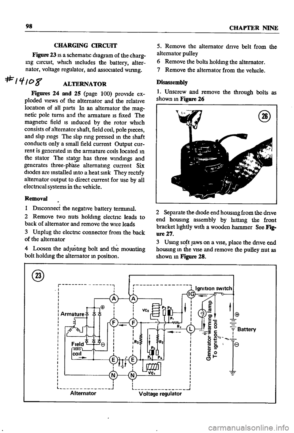
Figure
23
IS
a
schematIc
dIagram
of
the
charg
Ing
CIrcuIt
whIch
mcludes
the
battery
alter
nator
voltage
regulator
and
assocIated
wumg
f
08
ALTERNATOR
Figures
24
and
25
page
100
proVIde
ex
ploded
VIews
of
the
alternator
and
the
relatIve
locatIon
of
all
parts
In
an
alternator
the
mag
netic
pole
turns
and
the
armature
IS
fixed
The
magnetIc
field
IS
Induced
by
the
rotor
wh1ch
consists
of
alternator
shaft
field
coIl
pole
pIeces
and
slIp
nngs
The
slIp
rmg
pressed
In
the
shaft
conducts
only
a
small
field
current
Output
cur
rent
is
generated
In
the
armature
COIls
located
In
the
stator
The
stator
has
three
wIndmgs
and
generates
three
phoase
alternatIng
current
Six
dIodes
are
Installed
mto
a
heat
SInk
They
rectIfy
alternator
output
to
direct
current
for
use
by
all
electrIcal
systems
in
the
vehicle
Removal
1
DIsconnect
the
negatIve
battery
terrmnal
2
Remove
two
nuts
holdIng
electnc
leads
to
back
of
alternator
and
remove
the
Wire
leads
3
Unplug
the
electrIc
connector
from
the
back
of
the
alternator
4
Loosen
the
adJustlng
bolt
and
the
mounting
bolt
holdIng
the
alternator
In
positIon
@
r
I
I
I
L
Alternator
5
Remove
the
alternator
dnve
belt
from
the
alternator
pulley
6
Remove
the
bolts
holdmg
the
alternator
7
Remove
the
alternator
from
the
veh1cle
Disassembly
1
Unscrew
and
remove
the
through
bolts
as
shown
m
Figure
26
@
2
Separate
the
dIOde
end
housmg
from
the
dnve
end
hOUSIng
assembly
by
hlttmg
the
front
bracket
lIghtly
WIth
a
wooden
hatnnler
See
Fig
ure27
3
Usmg
SO
t
Jaws
on
a
VIse
place
the
dnve
end
housmg
m
the
VIse
and
remove
the
pulley
nut
as
shown
m
Figure
28
Cl
E
C
c5
i
u
5
o
l
co
c
c
0
1
T
Battery
r
r
L
J
Voltage
regulator
Page 110 of 252
ENGINE
ELECTRICAL
SYSTEM
105
VOLTAGE
REGULATOR
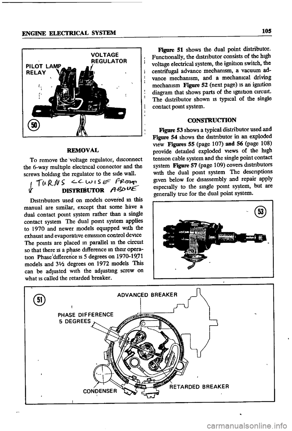
REMOVAL
To
remove
the
voltage
regulator
dISconnect
the
6
way
multIple
electrIcal
COlInector
and
the
screws
holdmg
the
regulator
to
the
SIde
wall
lJ
R
ftl5
C
Wt
Str
Ii
DISTRIBUTOR
W
I
vE
Dlstnbutors
used
on
models
covered
m
this
manual
are
SImilar
except
that
some
have
a
dual
contact
pomt
system
rather
than
a
single
contact
system
The
dual
pomt
system
applies
to
1970
and
newer
models
eqUIpped
With
the
exhaust
and
evaporatIve
ermsslOn
control
deVIce
The
pomts
are
placed
m
parallel
In
the
circuIt
so
that
there
IS
a
pqase
dIfference
In
their
opera
tIon
Phase
dlfference
IS
5
degrees
on
1970
19
71
models
and
31h
degrees
on
1972
models
This
can
be
adjusted
With
the
adjustIng
screw
on
what
IS
called
the
retarded
breaker
Figure
51
shows
the
dual
point
distributor
FunctIonally
the
dIStnbutor
consists
of
the
hIgh
voltage
electrical
system
the
ignitIon
switch
the
centrifugal
advance
mechanISm
a
vacuum
ad
vance
mechanIsm
and
a
mechanIcal
driving
mechanISm
Figure
52
next
page
IS
an
ignItion
diagram
that
shows
parts
of
the
IgnItIon
CIrCUIt
The
dIstributor
shown
IS
typIcal
of
the
single
contact
pomt
system
CONSTRUCTION
Figure
53
shows
a
typical
distributor
used
and
Figure
54
shows
the
dIStnbutor
in
an
exploded
VIeW
Figures
55
page
107
and
56
page
108
provide
detaIled
exploded
VIews
of
the
lugh
tenSIon
cable
system
and
the
single
point
contact
system
Figure
57
page
109
covers
dIStrIbutors
With
the
dual
pOInt
system
The
descnptions
given
below
for
dIsassembly
and
repair
apply
espeCIally
to
the
smgle
pOInt
system
but
are
generally
true
for
the
dual
point
system
@
@
ADVANCED
BREAKER
PHASE
DIFFERENCE
5
DEGREES
Page 132 of 252
CHAPTER
ELEVEN
CLUTCH
TRANSMISSION
AND
DRIVESHAFf
CLUTCH
i
es
ription
Datsun
uses
a
single
dry
dtsc
clutch
with
dIaphragm
spring
The
major
components
are
clutch
cover
pressure
plate
dIaphragm
spring
and
WIre
nngs
The
clutch
dISC
has
riveted
plates
on
both
surfaces
and
coll
spnngs
arranged
in
a
link
The
coll
springs
absorb
shock
to
soften
and
smooth
clutch
engagement
Figure
1
next
page
is
an
exploded
diagram
of
the
clutch
assembly
Clutch
Removal
The
transmIssion
must
be
separated
from
the
engme
to
remove
tlte
clutch
assembly
This
can
be
done
by
removmg
the
transmISSIon
and
engme
from
the
vehicle
as
a
umt
or
by
remoVIng
the
transmiSSIon
separately
Removal
of
the
engine
and
transmissIOn
IS
descnbed
In
Chapter
Six
Removal
of
the
transmISSIon
only
IS
descnbed
later
in
tills
chapter
Outcb
Disassembly
1
Separate
clutch
assembly
from
flywheel
Loosen
and
remove
bolts
dIagonally
and
gradu
ally
as
shown
m
Figure
2
2
Remove
dust
cover
from
clutch
housmg
3
Remove
return
spnng
from
beanng
sleeve
Separate
the
Withdrawal
lever
from
bearing
sleeve
w
1
4
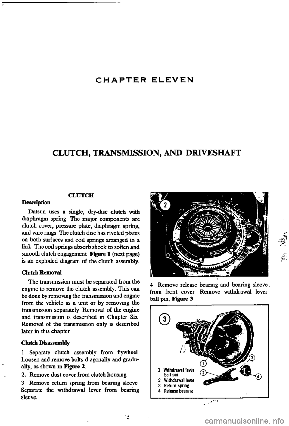
Remove
release
bearmg
and
bearing
sleeve
from
front
cover
Remove
wIthdrawal
lever
ball
pm
Figure
3
CD
1
Withdrawal
lever
ball
pin
2
Withdrawal
lever
3
Return
spnng
4
Release
beanng
4
Page 156 of 252

DIFFERENTIAL
REAR
AXLE
AND
REAR
SUSPENSION
151
4
Lower
the
Jack
and
r
move
dIfferentIal
from
rear
of
vehIcle
See
Figure
4
After
removal
sup
port
suspensIon
member
wIth
a
stand
to
prevent
distortlon
and
damage
to
the
Insulators
Differential
Inspection
Sedan
The
followmg
mspectIon
can
be
done
WIthout
disassembly
of
the
dIfferential
If
abnormalitIes
or
damage
eXiSts
refer
further
servIce
and
reparr
to
your
dealer
1
Check
the
tooth
contact
pattern
With
lead
oXide
at
two
or
three
pomts
after
removmg
rear
cover
Refer
to
Figure
5
which
shows
the
cor
rect
contact
pattern
If
the
contact
pattern
IS
m
correct
dIsassembly
and
adjustment
of
dIffer
entlalls
reqUIred
CD
TOE
HEEL
DRIVE
SIDE
HEEL
COAST
SIDE
2
Use
a
dIal
mdtcator
to
measure
backlash
be
tween
the
dnve
gear
and
pmIOn
Backlash
should
be
0
0039
to
0
0079
m
0
10
to
o
20mm
Check
all
gear
teeth
for
damage
and
cracks
3
Check
runout
at
the
rear
of
the
dnve
gear
If
the
tooth
contact
pattern
or
backlash
IS
ab
normal
Runout
should
be
less
than
00031
m
0
08mm
See
Figure
6
4
Rotate
the
gears
and
lIsten
for
SignS
of
de
fective
bearmgs
If
noises
are
eVIdent
the
dIf
ferential
must
be
dIsassembled
and
repaired
CD
Diflerentiallnstallation
Sedan
1
Mount
the
dIfferentIal
assembly
to
the
rear
suspensIOn
member
2
FIt
the
dIfferentIal
mountlng
member
to
the
fittmg
hole
by
pushIng
It
forward
with
a
bar
Torque
the
nuts
to
61
ft
lb
8
5
kg
m
3
Install
axle
dnve
shafts
dnve
shaft
and
handbrake
rear
cable
REAR
AXLE
AND
SUSPENSION
SEDAN
Figure
7
and
Figure
8
page
153
are
ex
ploded
dIagrams
of
the
sedan
rear
axle
and
suspensIOn
The
fully
independent
rear
suspen
SIon
IS
a
semI
traIlIng
arm
deSIgn
With
a
sus
penSIOn
member
suspensIOn
arms
coIl
spnngs
and
hydraulIc
shock
absorbers
The
wheel
bearings
are
lIfetime
lubncated
Rear
Axle
and
Suspension
Removal
Sedan
1
Jack
up
the
rear
of
the
veh1cle
and
support
It
on
stands
2
Remove
wheels
3
Refer
to
Figure
9
and
dtsconnect
handbrake
lInkage
and
rerum
sprmg
Remove
tall
pIpe
and
muffler
4
DISconnect
brake
hose
from
brake
tube
Re
move
four
bolts
holdmg
dnve
shaft
to
dIf
ferential
Lower
dnve
shaft
gently
to
ground