1968 DATSUN 510 warning
[x] Cancel search: warningPage 17 of 252

12
CHAPTER
THREE
13
IMPROPER
IDLE
MIXTURE
Roats
slowly
between
13
17
14
SMALl
SPARK
GAP
or
DEFECTIVE
POINTS
Slight
float
between
14
16
ignItIOn
switch
If
the
starter
still
fails
to
crank
properly
remove
the
starter
and
test
it
2
Starter
turns
but
does
not
engage
with
engine
This
trouble
is
usually
a
defective
pInion
or
sole
noid
shlfting
fork
It
may
also
be
that
the
teeth
on
the
pInion
flywheel
ring
gear
or
both
are
worn
down
too
far
to
engage
properly
3
Starter
engages
but
will
not
dISengage
when
IgmtlOn
switch
IS
released
TIns
trouble
is
usually
caused
by
a
sticking
sole
nOid
but
occasionally
the
pmlOn
can
jam
on
the
flywheel
With
manual
transmissions
the
pinion
can
be
temporanly
freed
by
rockmg
the
car
in
high
gear
Naturally
this
IS
not
poSSible
in
auto
matics
the
starter
must
be
removed
4
Loud
grinding
noISes
when
starter
runs
TIns
usually
means
the
teeth
on
the
pinion
and
or
flywheel
are
not
meshing
properly
It
may
also
mean
the
over
running
clutch
IS
broken
In
the
first
case
remove
the
starter
and
examine
the
gear
teeth
In
the
latter
remove
the
starter
and
replace
the
pmion
dnve
assembly
CHARGING
SYSTEM
Charging
system
troubles
may
be
in
the
alter
nator
voltage
regulator
or
fan
belt
The
follow
ing
symptoms
are
typical
1
Alternator
warning
lamp
does
not
come
on
when
IgmtlOn
is
turned
on
This
may
indicate
a
defective
ignition
switch
battery
voltage
regulator
or
lamp
Frrst
try
to
15
HEAD
GASKET
LEAK
Roats
between
5
19
16
RESTRICTm
EXHAUST
SYSTEM
Normal
when
first
started
Drops
to
0
as
rpm
Increases
May
eventually
rrse
to
about
16
start
the
car
If
it
doesn
t
start
check
the
igllltlon
sWitch
and
battery
If
the
car
starts
find
the
voltage
regulator
and
disconnect
the
wlute
red
Wire
this
is
the
lamp
wire
Ground
the
wire
If
the
lamp
hghts
the
voltage
regulator
is
defective
not
properly
grounded
try
tightening
the
mounting
screws
or
the
alternator
brushes
are
not
contactmg
the
commutator
If
the
lamp
does
not
light
when
the
wire
IS
grounded
the
lamp
is
probably
burned
out
replace
It
2
Alternator
warning
lamp
comes
on
and
stays
on
This
usually
mdicates
that
no
chargmg
is
takmg
place
Frrst
check
the
fan
belt
tension
and
adlust
if
necessary
Check
the
battery
condition
with
the
hydrometer
and
check
all
electrical
connec
tions
m
the
chargmg
system
Fmally
isolate
the
trouble
to
the
alternator
or
voltage
regulator
3
Alternator
warmng
lamp
flashes
erratically
This
usually
indicates
the
chargmg
system
is
workmg
intermittently
Check
the
fan
belt
ten
sion
and
all
electncal
connections
m
the
charg
ing
system
Check
alternator
brushes
and
cODlh
tlon
of
the
commutator
4
Baltery
reqUires
frequent
additiOns
of
water
or
lamps
require
frequent
replacement
The
alternator
IS
probably
overchargmg
the
bat
tery
The
voltage
regulator
is
probably
faulty
check
it
using
the
procedures
given
in
Chaper
Nme
5
ExceSSive
noISe
from
he
alternator
Check
for
loose
alternator
mountmg
The
Page 18 of 252

TROUBLESHOOTING
13
trouble
may
also
be
worn
bearings
Remove
the
alternator
and
repair
ENGINE
These
procedures
assume
the
starter
cranks
the
engme
over
normally
If
not
refer
to
Starter
section
m
this
chapter
1
Engme
won
t
start
Could
be
caused
by
the
IgOltlon
or
fuel
problems
First
determine
If
high
voltage
to
spark
plug
occurs
To
do
thiS
dISconnect
one
of
the
spark
plug
wires
Hold
the
exposed
wrre
termlOal
y
to
Y2
lOch
from
ground
any
metal
in
engine
com
partment
With
an
msulated
screwdriver
Crank
the
engme
over
If
sparks
do
not
Jump
to
ground
or
the
sparks
are
very
weak
the
trouble
may
be
10
the
IgnitIOn
system
See
Ignition
System
Trou
bleshootmg
to
further
check
If
sparks
occur
properly
the
trouble
may
be
10
the
fuel
system
See
Fuel
System
Troubleshootmg
2
Engme
misses
steadily
Remove
one
spark
plug
wrre
at
a
tune
and
ground
the
wrre
If
engme
mISs
increases
that
cyhnder
was
work
109
properly
Reconnect
the
wire
and
check
the
others
When
a
wire
IS
dIs
connected
and
engme
miss
remams
the
same
that
cylinder
IS
not
finng
Check
spark
as
descnbed
10
Step
1
If
no
spark
occurs
for
one
cyhnder
only
check
dlStnbutor
cap
wrre
and
spark
plug
If
spark
occurs
prop
erly
check
compressIOn
and
mtake
maOlfold
vacuum
to
ISolate
the
trouble
3
Engme
misses
erratlcally
at
all
speeds
Interrmttent
trouble
can
be
difficult
to
find
It
could
be
ill
the
Ignition
system
exhaust
system
or
fuel
system
Follow
troubleshooting
proce
dures
for
these
systems
carefully
to
isolate
the
trouble
4
Engme
misses
at
Idle
only
Trouble
could
exist
anywhere
ill
IgOltlon
system
Follow
Ignition
TroubleshootlOg
procedure
care
fully
Trouble
could
also
eXist
10
the
carburetor
Idle
crrcult
Check
Idle
mIXture
adjustment
and
check
for
restnctions
m
the
idle
crrcUlt
5
Engme
misses
at
high
speed
only
Problems
could
be
ill
the
fuel
or
IgOltlon
systems
heck
accelerator
pump
operation
fuel
pump
dehvery
fuel
hnes
etc
as
descnbed
under
Fuel
System
Troubleshootillg
Also
check
spark
plugs
and
wrres
6
Low
performance
at
all
speeds
poor
acceleratIOn
Trouble
usually
ill
IgOltlon
or
fuel
system
Check
each
With
the
appropnate
troubleshooting
pro
cedure
7
ExceSSive
fuel
consumptIOn
Could
be
caused
by
a
Wide
variety
of
seemmgly
unrelated
factors
Check
for
clutch
shppage
brake
drag
defective
wheel
beanngs
or
poor
front
end
alignment
Check
IgOltlOn
system
and
fuel
system
8
011
pressure
lamp
does
not
light
when
IgmtlOn
switch
IS
on
Check
the
alternator
warning
lamp
If
it
ISn
t
on
either
go
to
Step
1
Chargmg
System
Trouble
shootlOg
If
only
the
oil
pressure
lamp
IS
off
open
the
englOe
compartment
hd
and
locate
the
oil
pressure
sender
on
the
block
near
the
oil
filter
Make
sure
the
wrre
is
connected
to
the
sender
and
makmg
good
contact
Pull
the
wrre
off
and
ground
it
If
the
lamp
hghts
replace
the
sender
If
the
lamp
does
not
light
replace
the
lamp
9
011
pressure
lamp
lights
or
flickers
when
engme
IS
runmng
Indicates
low
or
complete
loss
of
oil
pressure
Stop
the
englOe
unmedmtely
coast
to
a
stop
With
the
clutch
dISengaged
Tlus
may
simply
be
caused
by
a
low
oil
level
or
an
overheatmg
en
glOe
Check
the
oil
level
and
fan
belt
tensIOn
Check
for
a
shorted
oil
pressure
sender
with
an
ohmmeter
or
a
contlOulty
tester
Remove
and
clean
the
oil
dipstick
and
check
oil
level
and
condition
RepleOlsh
or
replace
the
oil
as
re
qurred
Listen
for
unusual
nOISes
mdlcatmg
dam
aged
beanngs
etc
Do
not
re
start
the
engine
until
you
know
why
the
hght
went
on
and
are
sure
that
the
problem
has
been
corrected
IGNITION
SYSTEM
This
procedure
assumes
the
battery
IS
ill
good
enough
condition
to
crank
the
engme
at
a
normal
rate
Page 43 of 252
38
CHAPTER
SIX
EMISSION
CONTROL
DEVICES
All
Datsuns
have
a
sealed
type
of
crankcase
emISSion
control
device
and
an
exhaust
emISsion
control
deVice
Models
sold
m
Cahfornla
smce
1970
also
have
an
evaporative
emisSion
control
deVice
An
rmportant
part
of
the
exhaust
control
device
is
the
air
pump
located
at
the
bottom
left
hand
side
of
the
engme
It
IS
dnven
by
a
belt
off
of
the
crankshaft
pulley
and
supphes
air
to
the
exhaust
system
In
1972
an
electric
blower
in
corporated
m
the
air
cleaner
replaced
the
mechanical
pumI
ENGINE
REMOVAL
Expenence
has
shown
It
IS
easier
to
remove
the
engine
and
the
transmission
as
a
smgle
UnIt
than
to
remove
the
engme
alone
Once
the
en
gine
and
transmiSSIon
are
out
of
the
vehIcle
the
tranSmIssion
can
be
detached
from
the
engme
To
remove
the
engme
transmISsion
proceed
as
follows
1
Scribe
ahgnment
marks
on
the
hood
around
the
hmges
ThIS
will
make
remstallatlon
eaSIer
2
Remove
the
two
bolts
that
secure
each
hInge
and
remove
the
hood
It
is
not
necessary
to
re
move
the
hood
support
from
the
engme
firewall
3
DISconnect
the
lower
radIator
hose
from
the
right
hand
SIde
of
the
engine
and
at
the
bottom
of
the
radIator
ThIS
will
pernnt
coolant
to
dram
from
the
engme
and
the
radIator
4
Remove
the
draIn
plugs
from
the
engine
pan
and
translIDSsIon
and
completely
dram
lubn
cants
Into
suitable
contamers
5
DISconnect
the
battery
cables
from
the
bat
tery
loosen
the
two
hold
down
clamps
and
re
move
the
battery
NOTE
The
location
and
number
of
hoses
to
be
removed
from
the
air
cleaner
varies
from
model
to
model
It
IS
normally
easier
to
remove
the
hoses
from
the
sources
rather
than
try
to
dISconnect
them
from
yndemeath
the
air
cleaner
The
1972
model
Will
requlre
dlsconnectlOn
of
the
electrica1
cirCUit
In
the
air
cleaner
system
wing
nut
from
the
top
of
the
air
cleaner
and
remove
the
aIr
cleaner
7
DIsconnect
the
upper
radiator
hose
from
the
radiator
and
the
thermostat
housmg
Remove
the
hose
8
Disconnect
the
two
heater
hoses
from
the
nght
hand
side
of
the
engme
TIe
these
bac
so
they
won
t
interfere
with
removal
of
the
engme
9
Remove
the
radIator
grille
by
unscrewing
all
mountmg
screws
10
Remove
the
four
mounting
screws
holding
the
fan
shield
to
the
backside
of
the
radiator
11
Remove
the
four
mountmg
bolts
holdIng
the
radiator
In
place
In
automatic
tranSmISsion
models
dISconnect
the
two
transnnsslOn
oIl
cooler
lInes
from
the
bottom
of
the
radiator
Pull
the
radiator
straight
up
to
remove
Remove
the
fan
shield
12
Loosen
the
adjustment
and
mounting
bolts
from
the
retamIng
brackets
on
the
alternator
and
air
pump
If
so
eqwpped
The
alternator
is
lo
cated
at
the
bottom
nght
hand
Side
of
the
engme
and
the
air
pump
on
the
lower
left
hand
Side
13
Loosen
tenSIon
on
the
two
dnve
belts
re
move
the
belts
from
the
alternator
and
air
pump
and
then
from
the
fan
pulleys
14
Remove
the
bolts
holdIng
the
fan
and
pulley
to
the
water
pump
assembly
and
remove
the
fan
and
pulley
15
DISconnect
the
fuel
hne
from
the
fuel
pump
16
DIsco
ect
accelerator
control
linkage
and
choke
WIre
at
the
carburetor
17
Disconnect
the
wiring
from
the
starter
motor
alternator
Ignition
coIl
oIl
pressure
switch
and
temperature
transmItting
unit
NOTE
The
following
steps
are
per
formed
from
under
the
car
lack
up
the
front
of
the
car
and
position
stands
under
the
front
support
points
to
proVide
working
room
under
the
vehicle
WARNING
Never
climb
under
a
vehicle
that
is
supported
by
the
lack
only
If
stands
are
not
avflllable
sturdy
wooden
blocks
can
be
U3ed
6
Disconnect
all
hoses
that
lead
to
the
air
cleaner
remove
two
bolts
that
hold
the
air
cleaner
to
its
mountmg
bracket
unscrew
the
18
Remove
two
bolts
holdIng
the
clutch
operat
Ing
cylInder
to
the
flywheel
hOUSIng
shown
m
Page 87 of 252
82
CHAPTER
SEVEN
Removal
Pick
up
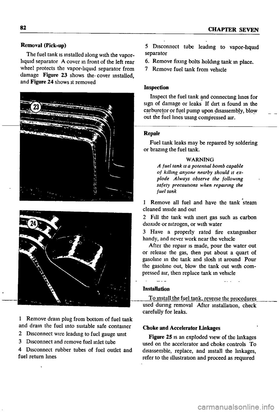
The
fuel
tank
IS
mstalled
along
With
the
vapor
liqUid
separator
A
cover
m
front
of
the
left
rear
wheel
protects
the
vapor
lIqUid
separator
from
damage
Figure
23
shows
the
cover
mstalled
and
Figure
24
shows
It
removed
I
Remove
dram
plug
from
bottom
of
fuel
tank
and
dram
the
fuel
mto
sUitable
safe
contamer
2
Disconnect
wire
leadmg
to
fuel
gauge
unIt
3
Disconnect
and
remove
fuel
Inlet
tube
4
Disconnect
rubber
tubes
of
fuel
outlet
and
fuel
return
lInes
5
Disconnect
tube
leadmg
to
vapor
liqUid
separator
6
Remove
fixmg
bolts
holdmg
tank
In
place
7
Remove
fuel
tank
from
vehIcle
Inspection
Inspect
the
fuel
tank
d
connectIng
lInes
for
SIgn
of
damage
or
leaks
If
dIrt
IS
found
In
the
carbl
relor
r
fuel
pump
upon
dlsassemb
y
blo
out
the
fuel
lines
usmg
compressed
air
Repair
Fuel
tank
leaks
may
be
repaired
by
soldering
or
brazmg
the
fuel
tank
WARNING
A
fuel
tank
IS
a
potential
bomb
capable
of
klllmg
anyone
nearby
should
It
ex
plode
Always
observe
the
followmg
safety
precautions
when
repairing
the
fuel
tank
1
Remove
all
fuel
and
have
the
tank
steam
cleaned
InSIde
and
out
2
F1l1
the
tank
WIth
Inert
gas
such
as
carbon
diOXide
or
mtrogen
or
WIth
water
3
Have
a
properly
rated
fire
extIngUisher
handy
and
never
work
near
the
vehicle
After
the
repair
IS
made
pour
the
water
out
or
release
the
gas
then
put
about
a
quart
of
gasolme
In
the
tank
and
slosh
It
around
Pour
the
gasolme
out
blow
the
tank
out
WIth
com
pressed
aIr
then
replace
tank
In
vehIcle
Installation
To
mstall
the
f
iel
tank
reverse
the
p
rocedur
used
dUring
removal
After
InstallatIon
check
carefully
for
leaks
Choke
and
Accelerator
Linkages
Figure
25
IS
an
exploded
VIew
of
the
lInkages
used
on
the
accelerator
and
choke
controls
To
disassemble
replace
and
mstall
the
lInkages
refer
to
the
IllustratIon
and
proceed
as
reqUIred
Page 204 of 252
18
I
70
I
69
72
lt
n
30
2
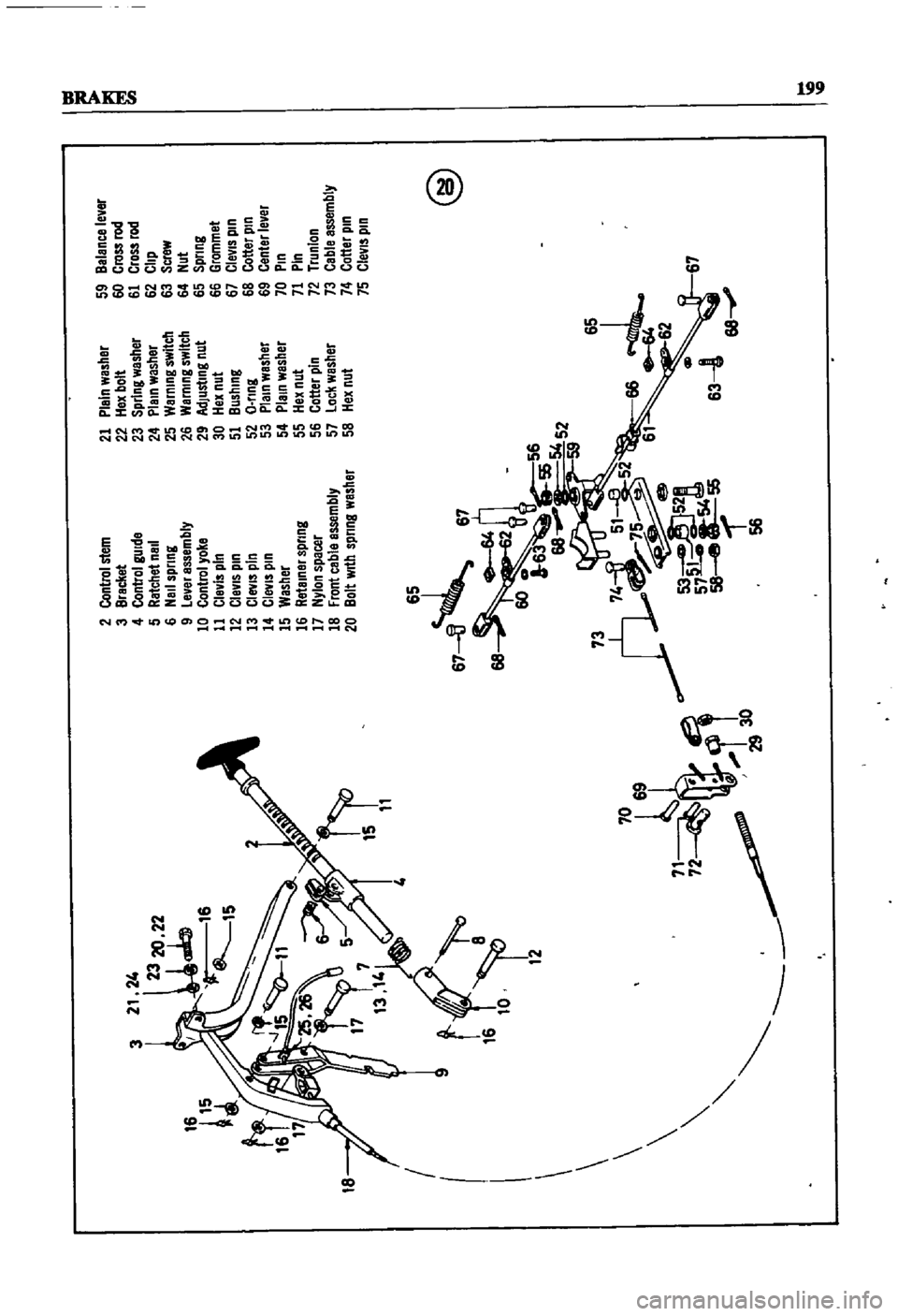
Control
stem
3
Bracket
4
Control
gUide
5
Ratchet
nail
6
NaIl
sprtng
9
Level
assembly
10
Control
yoke
11
Clevis
pin
12
ClevIs
pin
13
CleviS
pIn
1
CleviS
pIn
15
Washer
16
Retainer
spring
17
Nylon
spacer
18
Front
cable
assembly
20
Bolt
With
spring
washer
67
n
67
64
68
2
600
56
63
H
54
52
P73
74
i1
51
8
52
e
75
@
53
52a
57
55
58
8
56
21
Plain
washer
22
Hex
bolt
23
SprIng
washer
24
Plain
washer
25
Warning
switch
26
Warning
switch
29
Adjusting
nut
30
Hex
nut
51
Bushing
52
O
nng
53
Plain
washer
54
PlalO
washer
55
Hex
nut
56
Cotter
pIn
57
Lock
washer
58
Hex
nut
65
66
4
62
59
Balance
lever
60
Cross
rod
61
Cross
rod
62
Clip
63
Screw
64
Nut
65
Spring
66
Grommet
67
CleVIS
pin
68
Cotter
pin
69
Center
lever
70
Pin
71
Pin
72
Trunlon
73
Cable
assembly
74
Cotter
pin
75
CleVIS
pin
@
67
68
Ie
Ie
Page 213 of 252
1
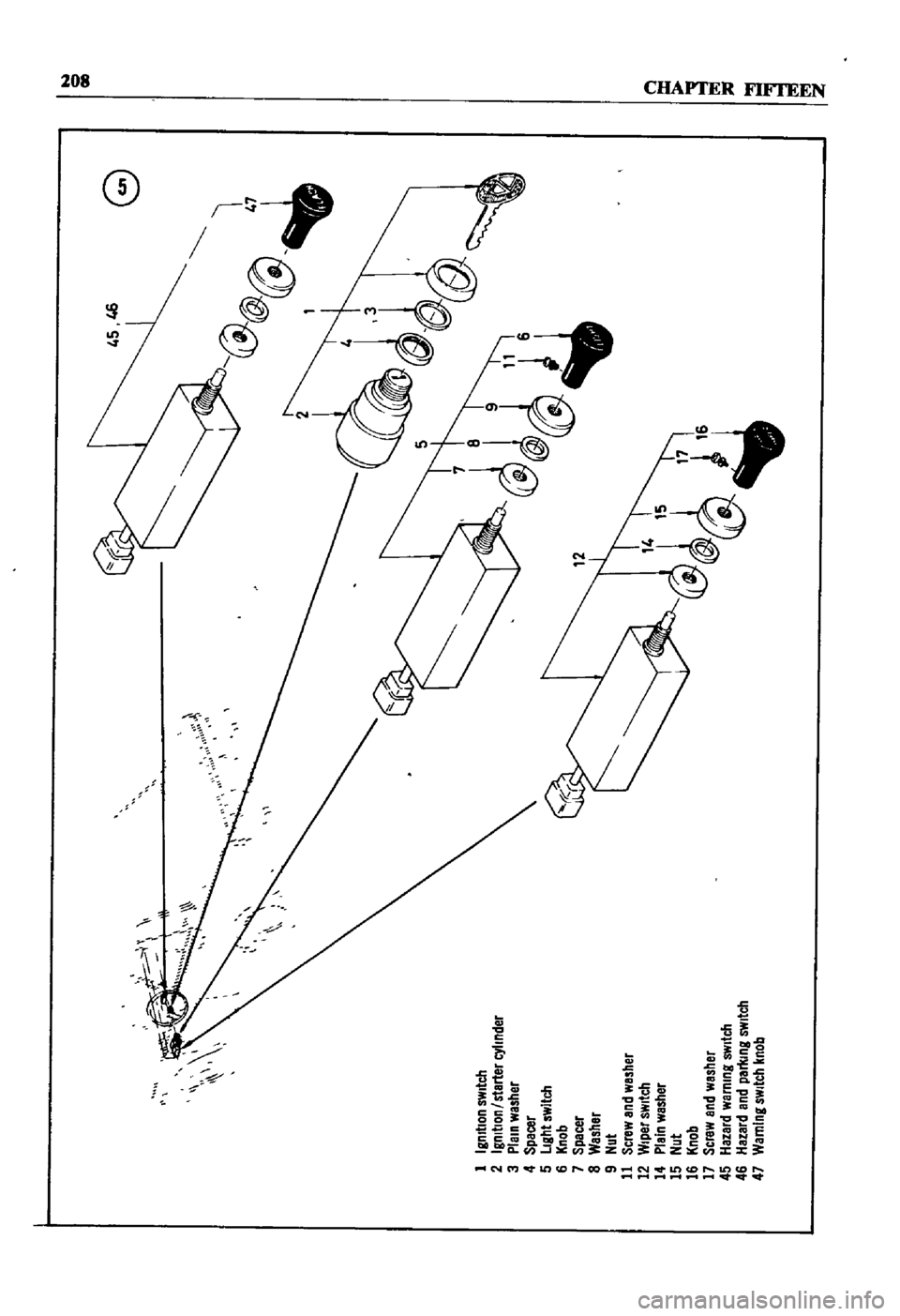
IgnItion
s
lItch
2
IgnitIOn
I
starter
nder
3
plain
wasMr
4
Spacer
5
Ight
swItch
6
jl
nob
7
Specet
S
WasMr
9
llOt
11
Screw
and
washer
12
Wiper
SWltc1l
1
Plain
wastier
1
i
llOt
16
jl
nob
17
Sere
ll
and
wasMr
i
Hazard
warnIng
SWitch
6
Hazard
and
pa1l
nlt
SWItch
1
warning
sWltc1l
I
nob
G
n
1
2
Page 214 of 252
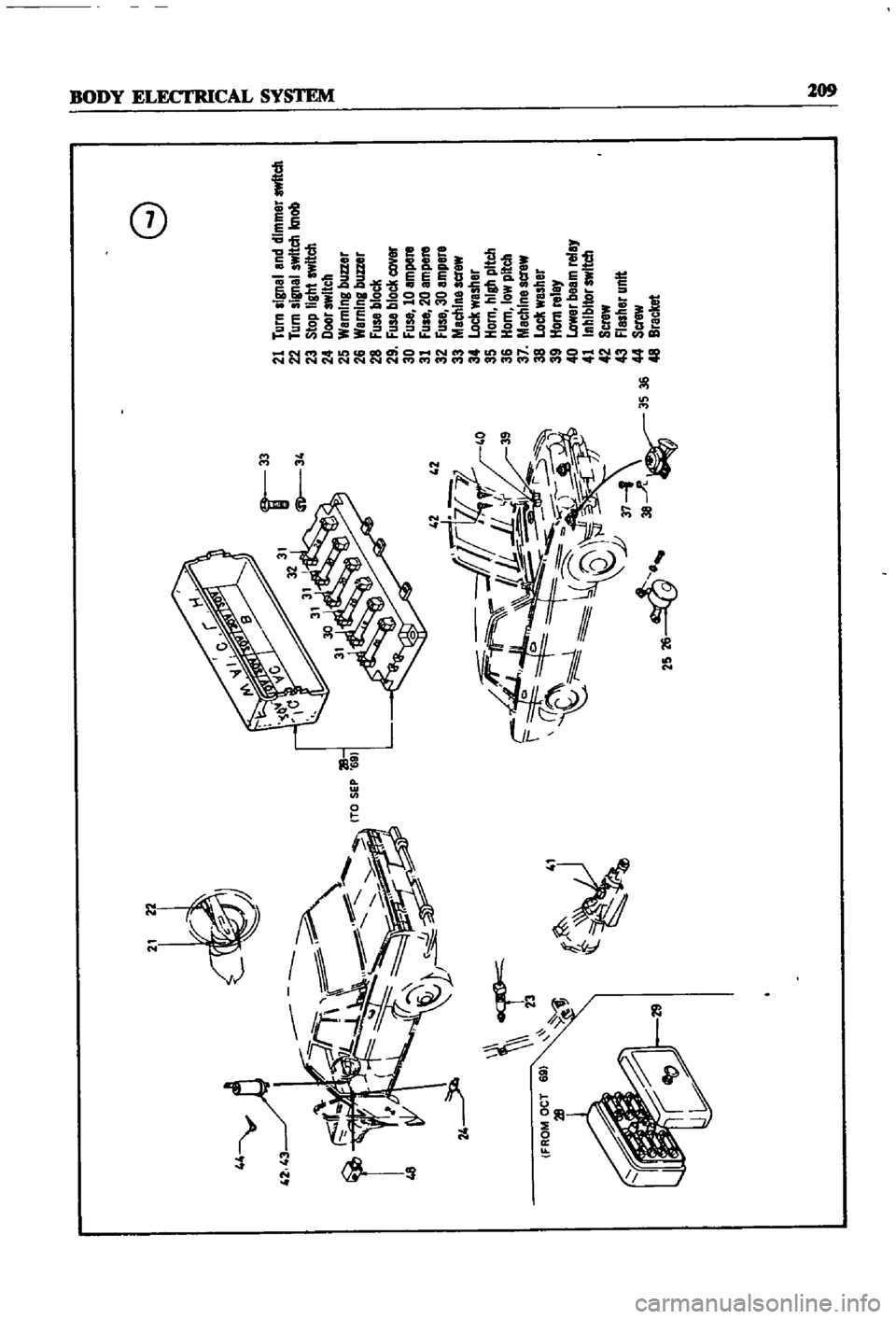
44
y
l
l
42
43
r
48
cr
23
41
f
Jj
it
d
F
1L
f7
IF
f
0
l
Q
U
lJ
37
1
2S
26
38
A
3S
36
G
21
Turn
signal
and
dimmer
switch
22
Turn
signal
switch
knob
23
Stop
light
switch
24
Door
switch
25
WarnIng
buzzer
26
Warning
buzzer
28
Fuse
block
29
Fuse
block
cover
30
Fuse
10
ampere
31
Fuse
20
ampere
32
Fuse
30
ampere
33
Machlnescrew
34
Lock
washer
35
Horn
hIgh
pitch
36
Horn
low
pitch
37
Machine
acrew
38
Lock
washer
39
Horn
relay
40
Lower
beem
relay
41
Inhibitor
switch
42
Screw
43
Flasher
unit
44
Screw
48
Bracket
o
i
Page 218 of 252
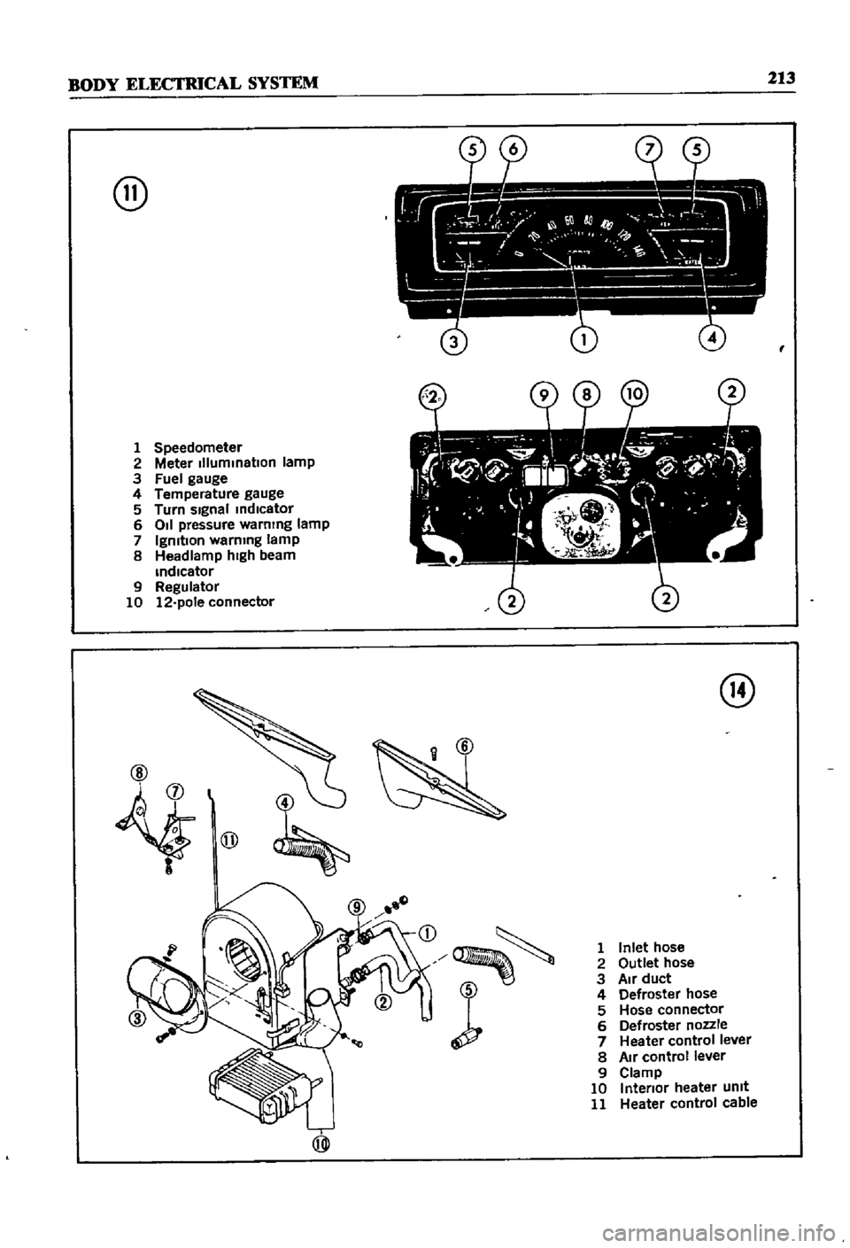
BODY
ELECTRICAL
SYSTEM
213
@
1
Speedometer
2
Meter
IIlummatlon
lamp
3
Fuel
gauge
4
Temperature
gauge
5
Turn
sIgnal
mdlcator
6
011
pressure
warning
lamp
7
IgnitIon
warning
lamp
8
Headlamp
hIgh
beam
mdlcator
9
Regulator
10
12
pole
connector
j
@
@
D
r
1
Inlet
hose
2
Outlet
hose
3
Air
duct
4
Defroster
hose
5
Hose
connector
6
Defroster
nozzle
7
Heater
control
lever
8
Air
control
lever
9
Clamp
10
Intenor
heater
Unit
11
Heater
control
cable