1968 DATSUN 510 engine coolant
[x] Cancel search: engine coolantPage 9 of 252
4
CHAPTER
ONE
chassIs
number
Write
the
numbers
down
and
carry
them
ill
your
wallet
Service
Hints
Throughout
thIs
manual
keep
two
conven
bons
ill
mmd
Front
refers
to
the
front
of
the
vehicle
The
left
and
nght
sides
of
the
ve
hicle
refer
to
a
person
sittIng
ill
the
car
facing
forward
For
example
the
steenng
wheelIS
on
the
left
hand
Side
All
dimensIOns
and
capacities
are
expressed
ill
units
fanuhar
to
a
Umted
States
mechaniC
such
as
illches
and
pounds
Metric
measurements
are
also
given
Metnc
tools
are
reqUITed
to
work
on
the
Datsun
CD
DATSUN
IENGINE
CAPACITY
IMAX
HP
RPM
IWHEELBASE
IENGINE
NUMBER
FAR
NO
NlSSAN
MOTOR
co
LTD
YOKOHAMA
JAPAN
TYPEI
510
1595
cc
961P
6600
rpm
mm
L
1
00988
P61
l
O
1
l
M
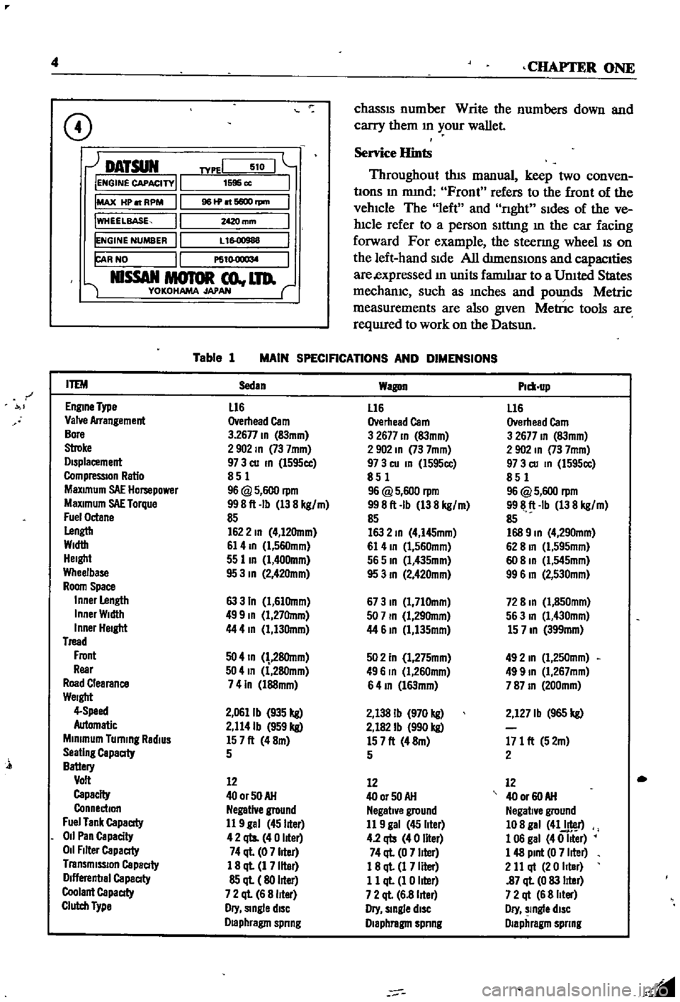
Table
1
MAIN
SPECIFICATIONS
AND
DIMENSIONS
r
ITEM
Sedan
Wagon
Plm
up
EnglDe
Type
L16
L16
L16
Valve
Arrangement
Overhead
Cam
Overhead
Cam
Overhead
Cam
Bore
3
26n
ID
83mm
3
2677
ID
83mm
3
2677
ID
83mm
Stroke
2902
ID
73
7mm
2
902
ID
73
7mm
2
902
In
73
7mm
Displacement
97
3
cu
ID
l595cc
97
3
cu
In
l595cc
97
3
cu
ID
1595cc
CompressIOn
Ratio
851
851
851
MaXimum
SAE
Hompower
96
@
5
600
rpm
96
@
5
600
rpm
96
@
5
600
rpm
MaXimum
SAE
Torque
998ft
Ib
138
kg
m
998ft
Ib
138
kg
m
9911
ft
Ib
138
kg
m
Fuel
Octane
85
85
85
Lengtb
1622
ID
4
12Omm
163
2
ID
4
I45mm
168
9
ID
4
290mm
Width
61
4
ID
l
560mm
61
4
ID
1
560mm
62
8
In
Cl
595mm
Height
55
lID
1
400mm
565
ID
Cl
435mm
60
8
ID
Cl
545mm
Wheelbase
95
3
ID
2
42Omm
95
3
ID
2
420mm
99
6
In
2
530mm
Room
Space
Inner
Length
63
3
In
1
61Omm
673
ID
1
710mm
72
8
ID
1
850mm
Inner
Width
499
ID
1
27Omm
507
ID
1
29Omm
563
In
1
430mm
Inner
Height
44
4
In
1
130mm
44
61D
1
135mm
15
7
ID
399mm
Tread
Front
50
4
ID
28Omm
502
In
1
275mm
492
In
1
250mm
Rear
504
In
1
280mm
496
In
Cl
260mm
499
ID
1
267mm
Road
Clearance
741n
l88mm
64
ID
l63mm
787
ID
200mm
Weight
4
Speed
2
0611b
935
kg
2
138
Ib
970
kg
2
127
Ib
965
kg
Automatic
2
114Ib
959
kg
2
182
Ib
990
kg
Minimum
Turning
RadiUS
157ft
48m
157ft
48m
171
ft
52m
Seating
Capaaty
5
5
2
Battery
Volt
12
12
12
Capacity
400rSOAH
400r50AH
40
or
60
AH
Connection
Negative
ground
Negative
ground
Negative
ground
Fuel
Tank
Capaaty
11
9
gal
45
liter
11
9
gal
45
liter
108
gal
41J
r
011
Pan
Capacity
42
qts
40
liter
4
2
qb
40
liter
1
06
gal
40
Iller
011
Filter
Capaaty
74
ql
07
liter
74
ql
0
7
liter
1
48
Pint
0
7
liter
Transmission
Capaaty
1
8
ql
1
7
liter
18
ql
1
7
Iller
2
11
qt
20
Iller
Dlflerenbal
Capaaty
85
ql
80
liter
11
ql
1
0
liter
87
ql
0
83
lIter
Coolant
Capaaty
7
2
ql
6
8
liter
7
2
ql
6
8
lIter
7
2
qt
6
8
Iller
Clutch
Type
Dry
Single
diSC
Dry
slDgle
diSC
Dry
slDgle
diSC
Draphragm
spnng
Diaphragm
spnng
Diaphragm
spnng
l
Page 11 of 252
CHAPTER
TWO
PERIODIC
MAINTENANCE
To
ensure
good
performance
dependability
and
safety
regular
penodlc
maintenance
is
necessary
TIns
chapter
outlInes
routine
and
penodlc
mamtenance
for
the
average
dnver
Under
heavy
usage
semcmg
mtervals
will
be
shortened
Regular
routme
mamtenance
will
help
aVOId
expensive
repaIrs
ROUTINE
CHECKS
The
followlDg
checks
should
be
performed
at
each
fuel
stop
1
Check
engme
oil
level
Top
up
as
requrred
2
Check
radiator
coolant
level
Top
up
as
re
qwred
3
Check
battery
electrolyte
The
battery
case
IS
marked
With
upper
hrmt
and
lower
lnmt
lInes
Level
should
be
maID
tamed
between
the
IIDes
4
Check
that
the
master
cylInder
brake
flwd
reservOir
level
IS
between
the
max
and
mm
lInes
marked
on
the
plastic
case
S
Check
the
plastic
clutch
cyhnder
reservoir
level
Level
should
be
between
the
max
and
mm
lInes
6
Check
the
windsh1eld
washer
flwd
reservoir
Top
up
as
required
7
Check
tire
pressures
when
the
tIres
are
cold
Front
and
rear
tire
pressures
should
be
24
pounds
under
normal
dnving
conditions
TIre
pressure
should
be
28
pounds
for
h1gh
speed
dnvmg
conditions
8
Check
the
engIne
for
general
conditIon
Check
for
leaky
or
cracked
hoses
and
loose
wmng
9
Check
condition
of
wmdshleld
wiper
blades
PERIODIC
CHECKS
Table
1
prOVIdes
penodIc
checks
and
main
tenance
that
should
be
performed
on
a
set
schedule
Table
2
gIves
recommended
lubncants
and
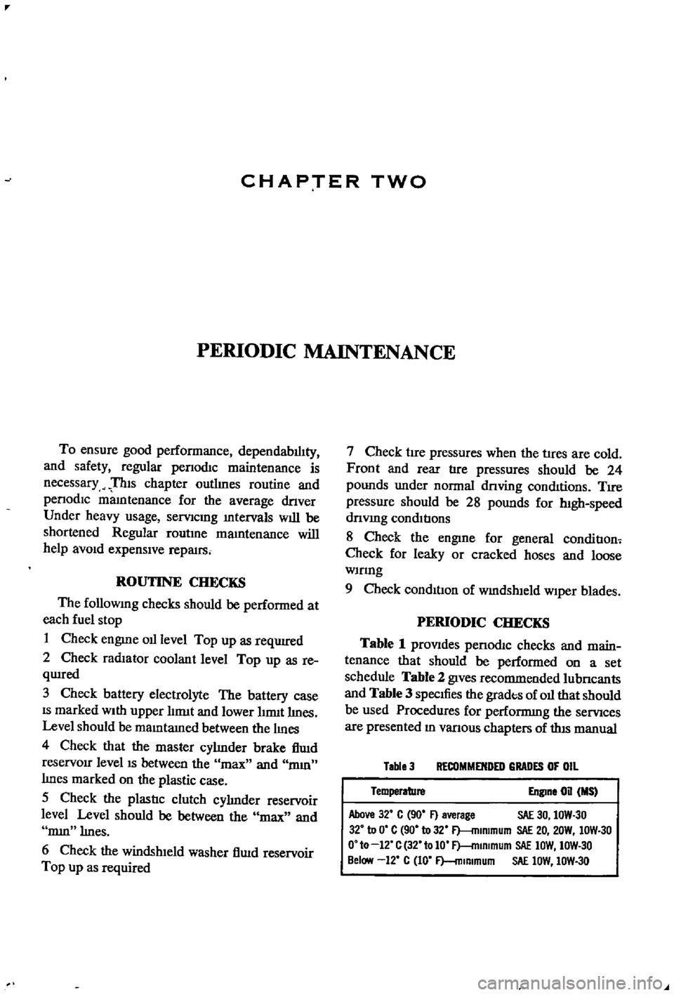
Table
3
specIfies
the
grades
of
oil
that
should
be
used
Procedures
for
performmg
the
semces
are
presented
ID
vanous
chapters
of
tlus
manual
Table
3
RECOMMENDED
GRADES
OF
OIL
Temperature
Engine
on
MS
Above
32
C
90
F
average
SAE
30
IOW
30
32
to
0
C
90
to
32
F
mlmmum
SAE
20
20W
IOW
30
O
to
12
C
32
tolO
F
mlRlmum
SAE
IOW
IOW
30
Below
12
C
10
F
mlmmum
SAE
lOW
IOW
30
Page 12 of 252

PERIODIC
MAINTENANCE
7
Table
1
ENGINE
LUBRICATION
AND
MAINTENANCE
FREQUENCY
EVERY
E
E
E
E
E
E
E
Eo
00
00
00
00
00
00
00
gq
00
00
00
NO
t
r61li
0
CD
Check
engine
011
level
top
up
If
required
X
Change
engine
011
X
Lubricate
carburetor
hnkage
X
Lubricate
distributor
rotor
shaft
and
ann
shaft
X
Apply
grease
to
distributor
cam
heel
X
Check
radiator
coolant
level
X
Change
radIator
coolant
X
Change
radiator
coolant
additive
X
Check
battery
electrolyte
level
X
Check
specific
gravity
of
battery
X
Check
engine
starting
exhaust
color
X
Tighten
cyhnder
head
manifolds
and
pipe
flanges
X
Adjust
valve
clearance
X
Check
Ignition
timing
X
Tighten
carburetor
fittings
X
Check
fan
belt
tension
X
Check
for
011
pan
leakage
X
Tighten
engine
mounts
X
Check
fuel
strainer
X
Replace
fuel
strainer
X
Check
for
fuel
leaks
X
Replace
011
filter
X
Check
spark
plugs
X
Replace
spark
plugs
X
Check
dlstnbutor
cap
rotor
and
POints
X
Adjust
engine
Idle
speed
X
Check
air
cleaner
fittings
X
Clean
011
filler
cap
X
Clean
battery
cables
and
terminals
X
Check
alternator
and
voltage
regulator
function
X
Check
starter
motor
function
X
Replace
aIr
cleaner
element
X
Check
fuel
pump
function
X
Check
cyhnder
compressIon
X
Clean
carburetor
Jets
and
float
chamber
X
Check
dlstnbutor
condenser
X
Check
crankcase
ventilation
control
valve
X
Page 43 of 252
38
CHAPTER
SIX
EMISSION
CONTROL
DEVICES
All
Datsuns
have
a
sealed
type
of
crankcase
emISSion
control
device
and
an
exhaust
emISsion
control
deVice
Models
sold
m
Cahfornla
smce
1970
also
have
an
evaporative
emisSion
control
deVice
An
rmportant
part
of
the
exhaust
control
device
is
the
air
pump
located
at
the
bottom
left
hand
side
of
the
engme
It
IS
dnven
by
a
belt
off
of
the
crankshaft
pulley
and
supphes
air
to
the
exhaust
system
In
1972
an
electric
blower
in
corporated
m
the
air
cleaner
replaced
the
mechanical
pumI
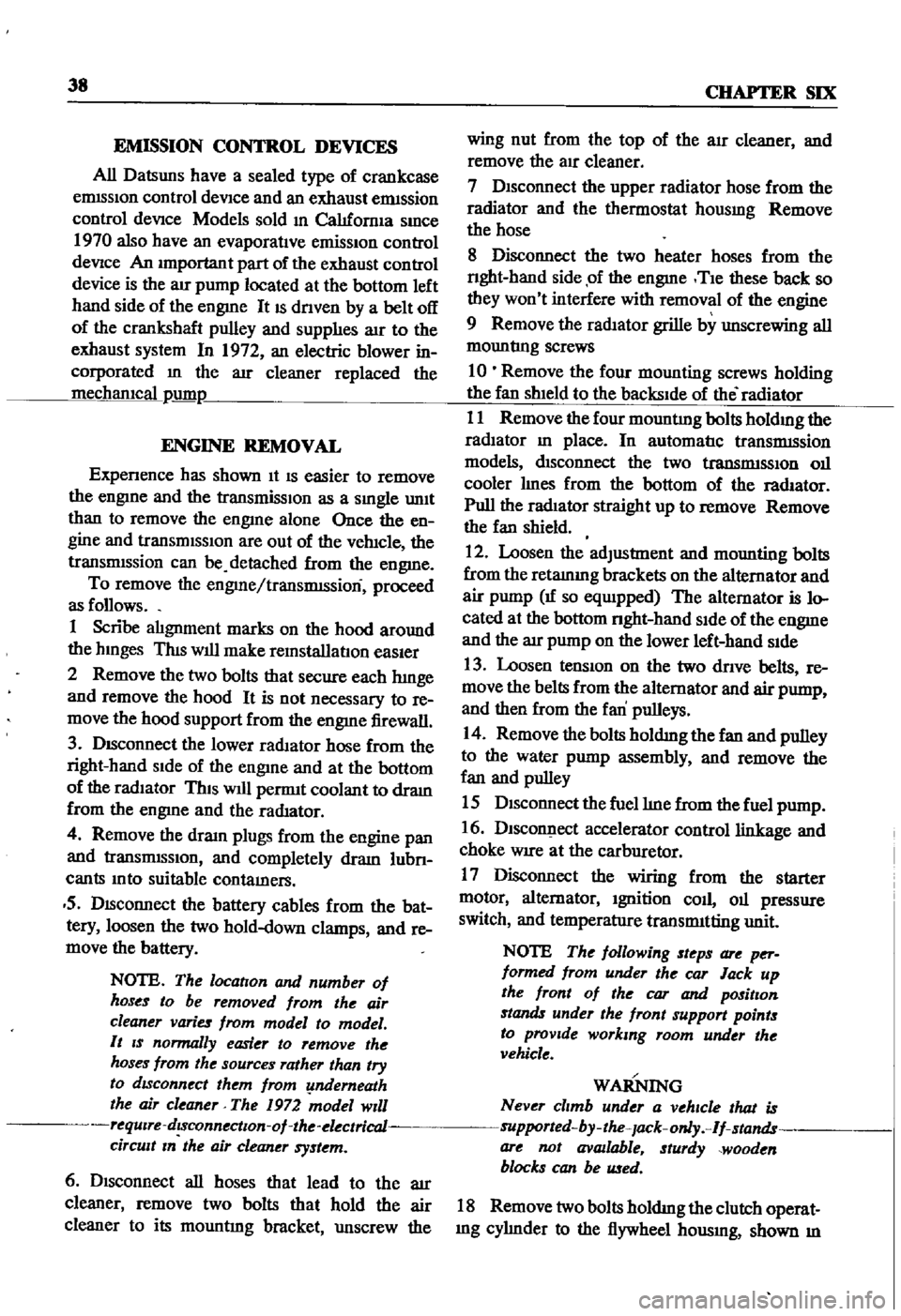
ENGINE
REMOVAL
Expenence
has
shown
It
IS
easier
to
remove
the
engine
and
the
transmission
as
a
smgle
UnIt
than
to
remove
the
engme
alone
Once
the
en
gine
and
transmiSSIon
are
out
of
the
vehIcle
the
tranSmIssion
can
be
detached
from
the
engme
To
remove
the
engme
transmISsion
proceed
as
follows
1
Scribe
ahgnment
marks
on
the
hood
around
the
hmges
ThIS
will
make
remstallatlon
eaSIer
2
Remove
the
two
bolts
that
secure
each
hInge
and
remove
the
hood
It
is
not
necessary
to
re
move
the
hood
support
from
the
engme
firewall
3
DISconnect
the
lower
radIator
hose
from
the
right
hand
SIde
of
the
engine
and
at
the
bottom
of
the
radIator
ThIS
will
pernnt
coolant
to
dram
from
the
engme
and
the
radIator
4
Remove
the
draIn
plugs
from
the
engine
pan
and
translIDSsIon
and
completely
dram
lubn
cants
Into
suitable
contamers
5
DISconnect
the
battery
cables
from
the
bat
tery
loosen
the
two
hold
down
clamps
and
re
move
the
battery
NOTE
The
location
and
number
of
hoses
to
be
removed
from
the
air
cleaner
varies
from
model
to
model
It
IS
normally
easier
to
remove
the
hoses
from
the
sources
rather
than
try
to
dISconnect
them
from
yndemeath
the
air
cleaner
The
1972
model
Will
requlre
dlsconnectlOn
of
the
electrica1
cirCUit
In
the
air
cleaner
system
wing
nut
from
the
top
of
the
air
cleaner
and
remove
the
aIr
cleaner
7
DIsconnect
the
upper
radiator
hose
from
the
radiator
and
the
thermostat
housmg
Remove
the
hose
8
Disconnect
the
two
heater
hoses
from
the
nght
hand
side
of
the
engme
TIe
these
bac
so
they
won
t
interfere
with
removal
of
the
engme
9
Remove
the
radIator
grille
by
unscrewing
all
mountmg
screws
10
Remove
the
four
mounting
screws
holding
the
fan
shield
to
the
backside
of
the
radiator
11
Remove
the
four
mountmg
bolts
holdIng
the
radiator
In
place
In
automatic
tranSmISsion
models
dISconnect
the
two
transnnsslOn
oIl
cooler
lInes
from
the
bottom
of
the
radiator
Pull
the
radiator
straight
up
to
remove
Remove
the
fan
shield
12
Loosen
the
adjustment
and
mounting
bolts
from
the
retamIng
brackets
on
the
alternator
and
air
pump
If
so
eqwpped
The
alternator
is
lo
cated
at
the
bottom
nght
hand
Side
of
the
engme
and
the
air
pump
on
the
lower
left
hand
Side
13
Loosen
tenSIon
on
the
two
dnve
belts
re
move
the
belts
from
the
alternator
and
air
pump
and
then
from
the
fan
pulleys
14
Remove
the
bolts
holdIng
the
fan
and
pulley
to
the
water
pump
assembly
and
remove
the
fan
and
pulley
15
DISconnect
the
fuel
hne
from
the
fuel
pump
16
DIsco
ect
accelerator
control
linkage
and
choke
WIre
at
the
carburetor
17
Disconnect
the
wiring
from
the
starter
motor
alternator
Ignition
coIl
oIl
pressure
switch
and
temperature
transmItting
unit
NOTE
The
following
steps
are
per
formed
from
under
the
car
lack
up
the
front
of
the
car
and
position
stands
under
the
front
support
points
to
proVide
working
room
under
the
vehicle
WARNING
Never
climb
under
a
vehicle
that
is
supported
by
the
lack
only
If
stands
are
not
avflllable
sturdy
wooden
blocks
can
be
U3ed
6
Disconnect
all
hoses
that
lead
to
the
air
cleaner
remove
two
bolts
that
hold
the
air
cleaner
to
its
mountmg
bracket
unscrew
the
18
Remove
two
bolts
holdIng
the
clutch
operat
Ing
cylInder
to
the
flywheel
hOUSIng
shown
m
Page 64 of 252

ENGINE
59
2
Coat
the
pan
gasket
on
both
sides
With
gasket
compound
and
attach
the
oil
pan
to
the
cyhnder
block
Torque
as
specIfied
Manifold
and
Carburetor
Installation
1
Install
the
mtake
and
exhaust
manIfolds
WIth
associated
gasket
to
the
cylmder
head
2
Mount
the
carburetor
and
gasket
to
the
mtake
manIfold
2
Adjust
all
mtake
and
exhaust
valves
to
the
specIfied
clearance
for
a
cold
engme
Clutch
Assembly
Installation
CAUTION
Take
extreme
care
not
to
get
grease
or
011
on
the
clutch
or
flywheel
frlc
hon
contact
surfaces
1
Place
the
clutch
disc
assembly
on
the
flywheel
With
the
longer
chamfered
splmed
end
of
the
dISC
toward
the
transmISSion
2
Visually
align
or
use
a
dummy
splmed
dnve
shaft
to
ahgn
the
diSC
assembly
With
the
flywheel
pilot
beanng
3
Install
and
tighten
the
SIX
bolts
holdmg
the
clutch
cover
assembly
to
the
flywheel
Tighten
the
bolts
a
turn
each
tune
by
diagonal
pattern
until
they
are
tight
Tlghtenmg
torque
should
be
174
to
188ft
lbs
24
to
2
6
kg
m
NOTE
There
are
two
dowels
on
the
flywheel
to
locate
the
clutch
cover
4
Remove
dummy
shaft
If
used
after
the
above
bolts
are
fully
tightened
5
Refit
the
release
bearing
and
translI11Ssion
case
Miscellaneous
Installation
1
Connect
the
fuel
hose
on
the
front
part
of
the
engme
to
the
fuel
pump
and
to
the
carburetor
2
Gap
the
spark
plugs
and
mstall
them
usmg
new
gaskets
3
Coat
the
rocker
arm
cover
gasket
With
sealer
and
position
It
on
the
cylmder
head
4
Install
the
rocker
arm
cover
and
tighten
the
two
thumb
screws
that
hold
it
m
place
5
Install
distrIbutor
makmg
certam
that
the
notch
on
the
distributor
shaft
assembly
mates
With
the
drive
spmdle
Ahgn
the
location
marks
made
dunng
disassembly
so
that
the
distrIbutor
is
positioned
as
before
6
Install
and
tighten
the
bolts
which
hold
the
dIStributor
to
the
front
cover
7
Install
pomts
condenser
and
rotor
8
Replace
distrIbutor
cap
and
attach
spark
plug
Wires
m
the
correct
sequence
Make
certain
that
all
wires
are
firmly
seated
m
the
distrIbutor
cap
and
attached
securely
to
the
spark
plugs
9
HOISt
the
engme
assembly
from
the
work
stand
10
Install
the
alternator
bracket
alternator
and
engme
mounts
to
the
block
11
Install
the
IgnItIon
coil
oil
filter
oil
pressure
SWitch
dipstick
and
water
drain
plug
12
Connect
the
vacuum
Ime
between
the
dis
trIbutor
and
carburetor
13
Connect
the
transIDlSSlOn
to
the
engine
prior
to
mstallatIon
m
the
vehicle
Engine
Installation
Installation
is
the
reverse
of
the
procedures
followed
m
removal
Be
certaIn
thatlall
battery
connections
are
made
that
water
hoses
are
se
cured
wmng
IS
connected
properly
and
that
all
required
bolts
and
mounts
are
mstalled
and
tightened
Replace
the
radiator
fan
belts
and
radiator
shroud
Fill
the
engme
With
the
proper
grade
of
oil
and
the
radiator
With
recommended
coolant
Install
the
hood
to
the
hInges
according
to
the
marks
made
dUrIng
removal
SERVICE
DATA
AND
SPECIFICATIONS
Table
1
covers
servIce
data
and
engme
Speci
fications
Page 90 of 252
COOLING
SYSTEM
8S
and
In
those
with
exhaust
and
evaporatIve
emIS
sion
control
devIces
a
fan
clutch
IS
combIned
WIth
the
thermostat
to
detect
temperature
m
the
engme
compartlnent
When
the
temperature
nses
the
thermostat
detects
the
change
an
the
fan
clutch
engages
thereby
helpmg
to
cool
the
engme
WATER
PUMP
Figure
2
page
86
IS
an
exploded
drawmg
of
the
water
pump
and
fan
assembly
for
1970
to
1971
The
top
half
of
the
IllustratIon
applIes
to
those
models
WIth
exhaust
and
evaporatIve
emiSSIOn
control
systems
The
bottom
half
covers
models
WIth
a
crankcase
emiSSIon
control
deVIce
only
Figure
3
page
87
IS
an
exploded
drawmg
of
the
water
pump
and
fan
assembly
for
1968
models
Without
exhaust
or
evaporatIve
controls
Figure
4
page
88
shows
the
1968
model
With
emISSIon
control
deVIce
As
can
be
seen
from
the
illustratIons
most
dIfferences
eXISt
withIn
the
fan
clutch
assembly
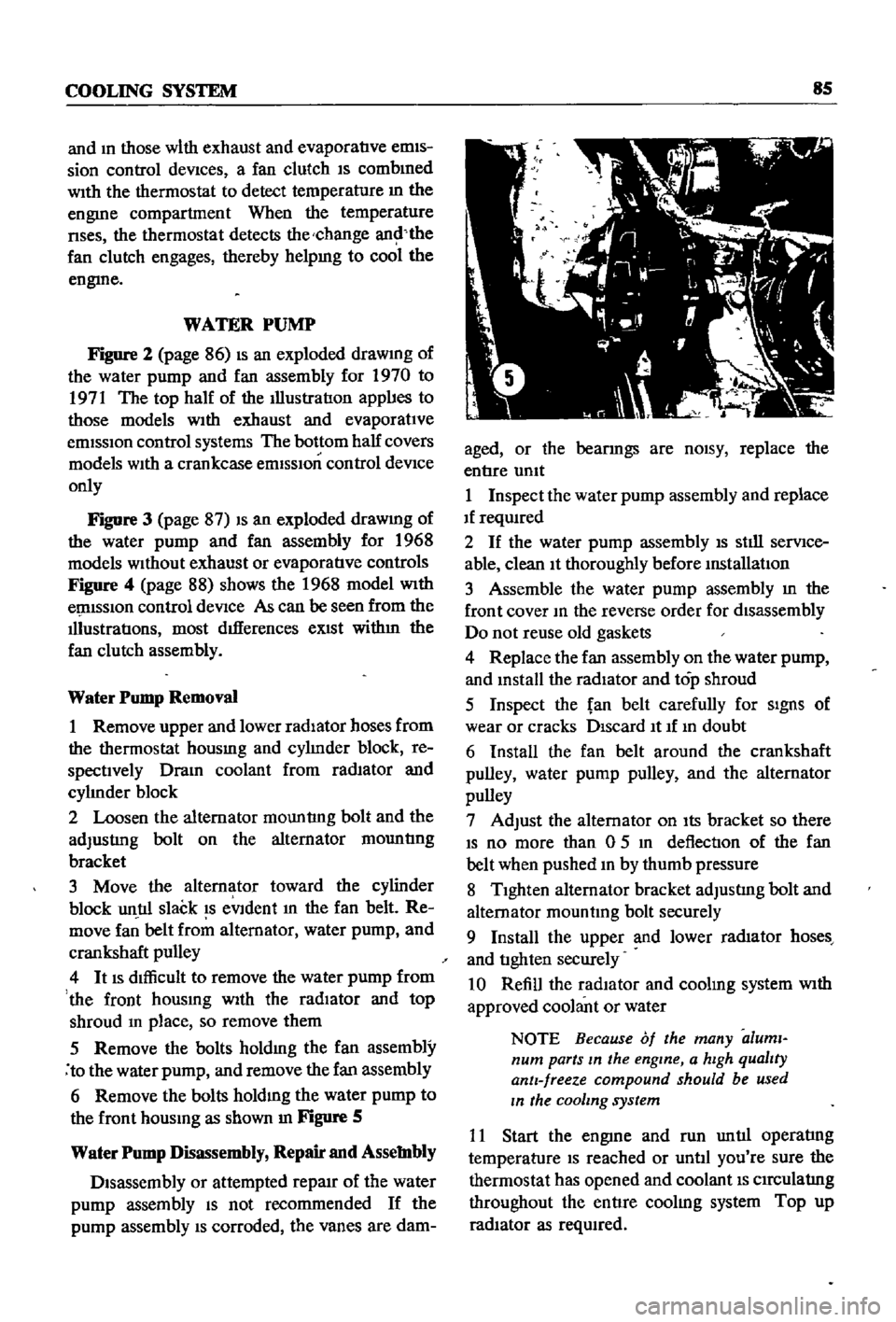
Water
Pump
Removal
1
Remove
upper
and
lower
radIator
hoses
from
the
thermostat
housmg
and
cylmder
block
re
spectIvely
Dram
coolant
from
rad1ator
and
cylInder
block
2
Loosen
the
alternator
mountlng
bolt
and
the
adjustIng
bolt
on
the
alternator
mountIng
bracket
3
Move
the
alternator
toward
the
cylinder
block
untIl
slack
IS
eVIdent
10
the
fan
belt
Re
move
fa
belt
fro
alternator
water
pump
and
crankshaft
pulley
4
It
IS
difficult
to
remove
the
water
pump
from
the
front
housmg
With
the
radiator
and
top
shroud
10
place
so
remove
them
5
Remove
the
bolts
holdmg
the
fan
assembly
to
the
water
pump
and
remove
the
fan
assembly
6
Remove
the
bolts
holdmg
the
water
pump
to
the
front
housmg
as
shown
In
Figure
S
Water
Pump
Disassembly
Repair
and
Assembly
Disassembly
or
attempted
repaIr
of
the
water
pump
assembly
IS
not
recommended
If
the
pump
assembly
IS
corroded
the
vanes
are
dam
aged
or
the
bearmgs
are
nOISY
replace
the
entIre
umt
1
Inspect
the
water
pump
assembly
and
replace
If
reqUIred
2
If
the
water
pump
assembly
IS
stIll
serVIce
able
clean
It
thoroughly
before
mstallatIon
3
Assemble
the
water
pump
assembly
m
the
front
cover
10
the
reverse
order
for
disassembly
Do
not
reuse
old
gaskets
4
Replace
the
fan
assembly
on
the
water
pump
and
mstall
the
radiator
and
top
shroud
5
Inspect
the
fan
belt
carefully
for
SIgnS
of
wear
or
cracks
DIscard
It
If
10
doubt
6
Install
the
fan
belt
around
the
crankshaft
pulley
water
pump
pulley
and
the
alternator
pulley
7
Adjust
the
alternator
on
Its
bracket
so
there
IS
no
more
than
0
5
10
deflection
of
the
fan
belt
when
pushed
10
by
thumb
pressure
8
TIghten
alternator
bracket
adjustIng
bolt
and
alternator
mountmg
bolt
securely
9
Install
the
upper
and
lower
rad1ator
hoses
and
tIghten
securely
10
Refill
the
radIator
and
coolmg
system
With
approved
coolant
or
water
NOTE
Because
of
the
many
aluml
num
parts
In
the
engine
a
hIgh
qualIty
antI
freeze
compound
should
be
used
In
the
cooling
system
11
Start
the
engme
and
run
untIl
operatIng
temperature
IS
reached
or
untIl
you
re
sure
the
thermostat
has
opened
and
coolant
IS
CIrCulatIng
throughout
the
entIre
coolIng
system
Top
up
radIator
as
reqUIred
Page 94 of 252
COOLING
SYSTEM
89
FAN
CLUTCH
Fan
Clutch
Operation
and
Inspection
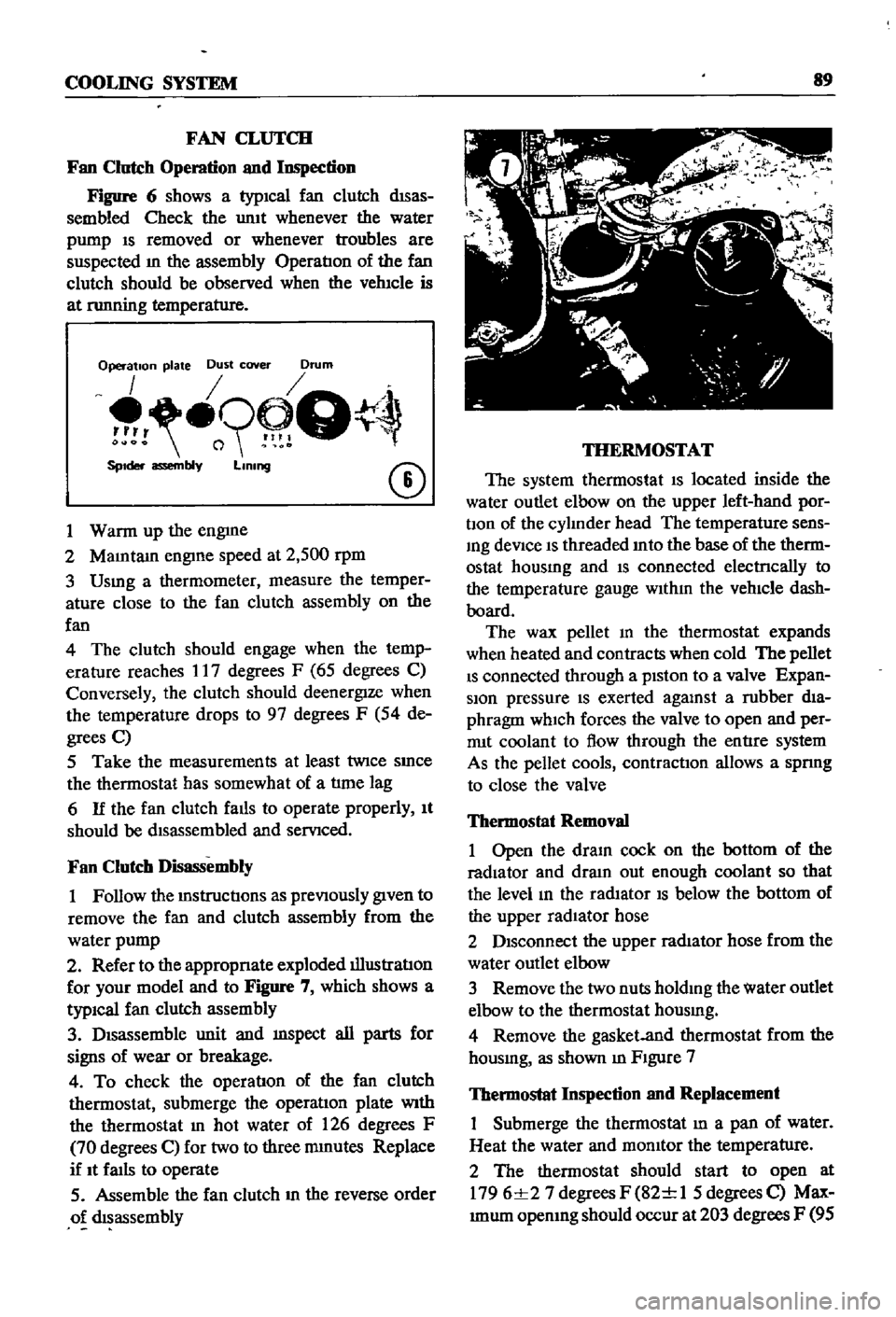
Figure
6
shows
a
typICal
fan
clutch
dISas
sembled
Check
the
umt
whenever
the
water
pump
IS
removed
or
whenever
troubles
are
suspected
m
the
assembly
OperatIon
of
the
fan
clutch
should
be
observed
when
the
vehIcle
is
at
nmning
temperature
Operation
plate
Dust
cover
Drum
o9
Q
SpIder
assembly
LIning
CD
1
Warm
up
the
engme
2
MaIntam
engIne
speed
at
2
500
rpm
3
Usmg
a
thermometer
measure
the
temper
ature
close
to
the
fan
clutch
assembly
on
the
fan
4
The
clutch
should
engage
when
the
temp
erature
reaches
17
degrees
F
65
degrees
C
Conversely
the
clutch
should
deenergIze
when
the
temperature
drops
to
97
degrees
F
54
de
grees
C
5
Take
the
measurements
at
least
twice
SInce
the
thermostat
has
somewhat
of
a
tlme
lag
6
If
the
fan
clutch
falls
to
operate
properly
It
should
be
dIsassembled
and
servIced
Fan
Clutch
Disassembly
1
Follow
the
mstructIons
as
prevIOusly
gIven
to
remove
the
fan
and
clutch
assembly
from
the
water
pump
2
Refer
to
the
appropnate
exploded
illustratIon
for
your
model
and
to
Figure
7
which
shows
a
typiCal
fan
clutch
assembly
3
DIsassemble
unit
and
mspect
all
parts
for
signs
of
wear
or
breakage
4
To
check
the
operatIon
of
the
fan
clutch
thermostat
submerge
the
operatIon
plate
With
the
thermostat
In
hot
water
of
126
degrees
F
70
degrees
C
for
two
to
three
mmutes
Replace
if
It
faIls
to
operate
5
Assemble
the
fan
clutch
m
the
reverse
order
o
dIsassembly
THERMOSTAT
The
system
thermostat
IS
located
inside
the
water
outlet
elbow
on
the
upper
left
hand
por
bon
of
the
cylInder
head
The
temperature
sens
Ing
deVice
IS
threaded
Into
the
base
of
the
therm
ostat
housmg
and
IS
connected
electrlcally
to
the
temperature
gauge
WIthIn
the
vehIcle
dash
board
The
wax
pellet
m
the
thermostat
expands
when
heated
and
contracts
when
cold
The
pellet
IS
connected
through
a
pIston
to
a
valve
Expan
sion
pressure
IS
exerted
agalUst
a
rubber
dIa
phragm
which
forces
the
valve
to
open
and
per
rrut
coolant
to
flow
through
the
entIre
system
As
the
pellet
cools
contractIOn
allows
a
spnng
to
close
the
valve
Thermostat
Removal
1
Open
the
draIn
cock
on
the
bottom
of
the
radiator
and
dram
out
enough
coolant
so
that
the
level
In
the
radIator
IS
below
the
bottom
of
the
upper
radIator
hose
2
DIsconnect
the
upper
radIator
hose
from
the
water
outlet
elbow
3
Remove
the
two
nuts
holdIng
the
water
outlet
elbow
to
the
thermostat
housmg
4
Remove
the
gasket
and
thermostat
from
the
housmg
as
shown
m
FIgure
7
Thermostat
Inspection
and
Replacement
Submerge
the
thermostat
In
a
pan
of
water
Heat
the
water
and
momtor
the
temperature
2
The
thermostat
should
start
to
open
at
1796
1
27
degrees
F
82
1
1
5
degrees
C
Max
Imum
opemng
should
occur
at
203
degrees
F
95