1968 DATSUN 510 weight
[x] Cancel search: weightPage 9 of 252
4
CHAPTER
ONE
chassIs
number
Write
the
numbers
down
and
carry
them
ill
your
wallet
Service
Hints
Throughout
thIs
manual
keep
two
conven
bons
ill
mmd
Front
refers
to
the
front
of
the
vehicle
The
left
and
nght
sides
of
the
ve
hicle
refer
to
a
person
sittIng
ill
the
car
facing
forward
For
example
the
steenng
wheelIS
on
the
left
hand
Side
All
dimensIOns
and
capacities
are
expressed
ill
units
fanuhar
to
a
Umted
States
mechaniC
such
as
illches
and
pounds
Metric
measurements
are
also
given
Metnc
tools
are
reqUITed
to
work
on
the
Datsun
CD
DATSUN
IENGINE
CAPACITY
IMAX
HP
RPM
IWHEELBASE
IENGINE
NUMBER
FAR
NO
NlSSAN
MOTOR
co
LTD
YOKOHAMA
JAPAN
TYPEI
510
1595
cc
961P
6600
rpm
mm
L
1
00988
P61
l
O
1
l
M
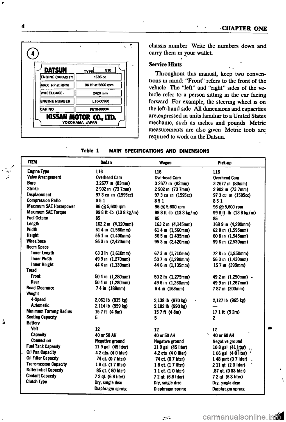
Table
1
MAIN
SPECIFICATIONS
AND
DIMENSIONS
r
ITEM
Sedan
Wagon
Plm
up
EnglDe
Type
L16
L16
L16
Valve
Arrangement
Overhead
Cam
Overhead
Cam
Overhead
Cam
Bore
3
26n
ID
83mm
3
2677
ID
83mm
3
2677
ID
83mm
Stroke
2902
ID
73
7mm
2
902
ID
73
7mm
2
902
In
73
7mm
Displacement
97
3
cu
ID
l595cc
97
3
cu
In
l595cc
97
3
cu
ID
1595cc
CompressIOn
Ratio
851
851
851
MaXimum
SAE
Hompower
96
@
5
600
rpm
96
@
5
600
rpm
96
@
5
600
rpm
MaXimum
SAE
Torque
998ft
Ib
138
kg
m
998ft
Ib
138
kg
m
9911
ft
Ib
138
kg
m
Fuel
Octane
85
85
85
Lengtb
1622
ID
4
12Omm
163
2
ID
4
I45mm
168
9
ID
4
290mm
Width
61
4
ID
l
560mm
61
4
ID
1
560mm
62
8
In
Cl
595mm
Height
55
lID
1
400mm
565
ID
Cl
435mm
60
8
ID
Cl
545mm
Wheelbase
95
3
ID
2
42Omm
95
3
ID
2
420mm
99
6
In
2
530mm
Room
Space
Inner
Length
63
3
In
1
61Omm
673
ID
1
710mm
72
8
ID
1
850mm
Inner
Width
499
ID
1
27Omm
507
ID
1
29Omm
563
In
1
430mm
Inner
Height
44
4
In
1
130mm
44
61D
1
135mm
15
7
ID
399mm
Tread
Front
50
4
ID
28Omm
502
In
1
275mm
492
In
1
250mm
Rear
504
In
1
280mm
496
In
Cl
260mm
499
ID
1
267mm
Road
Clearance
741n
l88mm
64
ID
l63mm
787
ID
200mm
Weight
4
Speed
2
0611b
935
kg
2
138
Ib
970
kg
2
127
Ib
965
kg
Automatic
2
114Ib
959
kg
2
182
Ib
990
kg
Minimum
Turning
RadiUS
157ft
48m
157ft
48m
171
ft
52m
Seating
Capaaty
5
5
2
Battery
Volt
12
12
12
Capacity
400rSOAH
400r50AH
40
or
60
AH
Connection
Negative
ground
Negative
ground
Negative
ground
Fuel
Tank
Capaaty
11
9
gal
45
liter
11
9
gal
45
liter
108
gal
41J
r
011
Pan
Capacity
42
qts
40
liter
4
2
qb
40
liter
1
06
gal
40
Iller
011
Filter
Capaaty
74
ql
07
liter
74
ql
0
7
liter
1
48
Pint
0
7
liter
Transmission
Capaaty
1
8
ql
1
7
liter
18
ql
1
7
Iller
2
11
qt
20
Iller
Dlflerenbal
Capaaty
85
ql
80
liter
11
ql
1
0
liter
87
ql
0
83
lIter
Coolant
Capaaty
7
2
ql
6
8
liter
7
2
ql
6
8
lIter
7
2
qt
6
8
Iller
Clutch
Type
Dry
Single
diSC
Dry
slDgle
diSC
Dry
slDgle
diSC
Draphragm
spnng
Diaphragm
spnng
Diaphragm
spnng
l
Page 23 of 252
18
CHAP1
lER
THlREE
c
c
c
ce
J
1
Ii
j
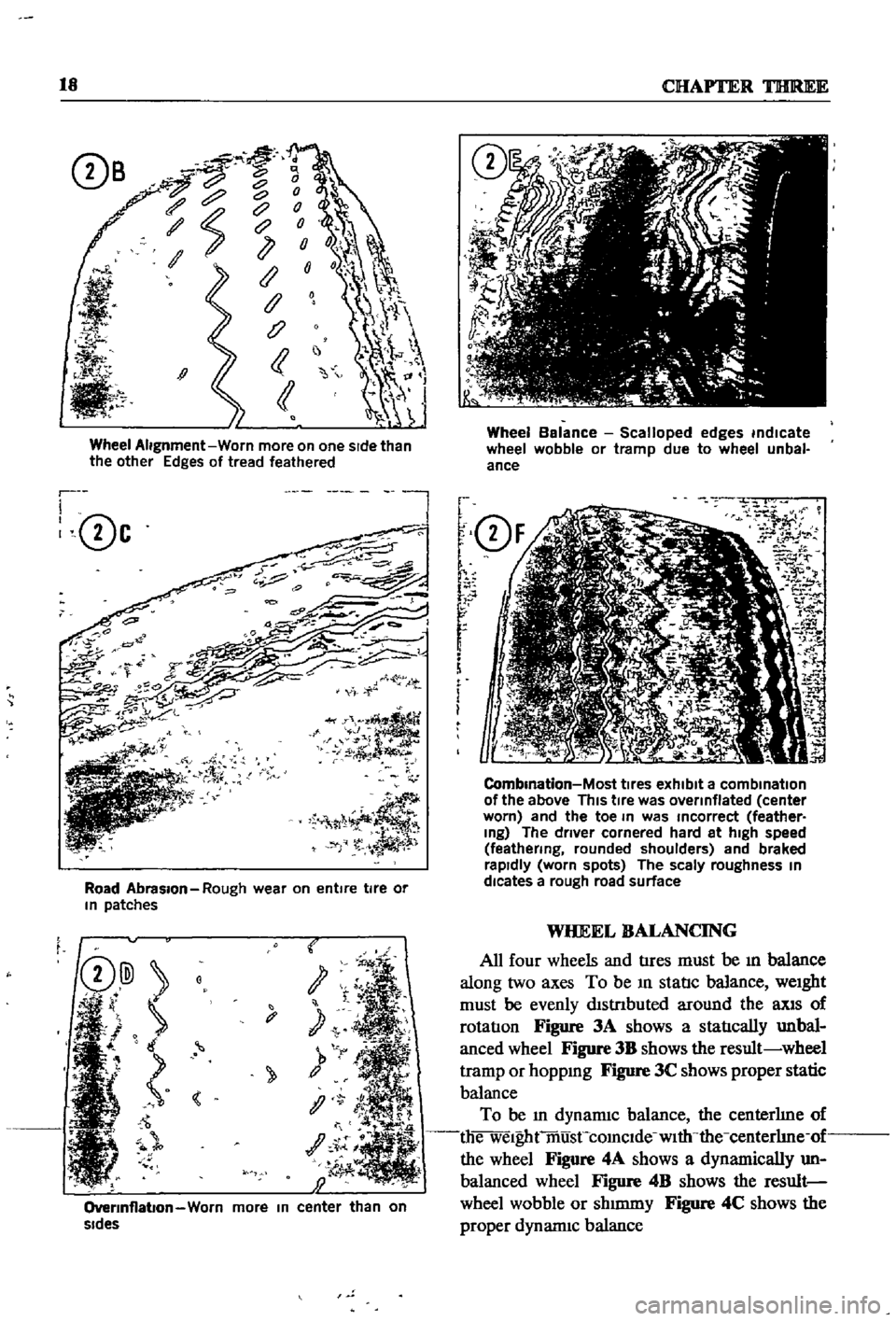
Wheel
Alignment
Worn
more
on
one
sIde
than
the
other
Edges
of
tread
feathered
r
I
0c
l
Road
Abrasion
Rough
wear
on
entire
tire
or
In
patches
t
y
1
OverInflabon
Worn
more
In
center
than
on
sides
Wheel
Balance
Scalloped
edges
indicate
wheel
wobble
or
tramp
due
to
wheel
unbal
ance
f
Q
F
r
r
r
f
i
m
i
O
2
7
iK
J
1
J
i
i
5J
CombInation
Most
tIres
exhibit
a
combination
of
the
above
This
tIre
was
overinflated
center
worn
and
the
toe
In
was
Incorrect
feather
Ing
The
driver
cornered
hard
at
high
speed
feathering
rounded
shoulders
and
braked
rapidly
worn
spots
The
scaly
roughness
In
dlcates
a
rough
road
surface
WHEEL
BALANCING
All
four
wheels
and
tIres
must
be
ill
balance
along
two
axes
To
be
ill
statIc
balance
weight
must
be
evenly
dlstnbuted
around
the
llXlS
of
rotatIon
Figure
3A
shows
a
statIcally
unbal
anced
wheel
Figure
3B
shows
the
result
wheel
tramp
or
hoppmg
Figure
3C
shows
proper
static
balance
To
be
ill
dynamiC
balance
the
centerhne
of
die
welghtmusCcomclde
with
the
centerhne
of
the
wheel
Figure
4A
shows
a
dynamically
un
balanced
wheel
Figure
4B
shows
the
result
wheel
wobble
or
shmuny
Figure
4C
shows
the
proper
dynannc
balance
Page 36 of 252
CHAPTER
SIX
ENGINE
Datsun
510
and
521
veJucles
use
the
L16
engme
Over
the
years
the
deSign
remamed
essentIally
the
same
with
nunor
changes
made
to
accommodate
drlIerent
elIDSSlon
control
de
VIces
The
Ll6
IS
a
four
cylmder
overhead
cam
shaft
engme
With
a
97
3
cubic
mch
1595cc
dISplacement
Cylmder
bore
IS
3
2677
in
83mm
stroke
IS
2
9016
m
73
7mm
Output
IS
96
horsepower
1972
mode1s
92
horse
power
at
5
600
rpm
Compression
ratIo
is
8
5
to
1
Equipment
includes
a
single
two
barrel
Hltaclu
carburetor
an
HItachi
alternator
an
HItachi
starter
motor
and
either
a
smgle
point
or
dual
pomt
distnbutor
Figure
1
next
page
IS
an
overall
view
of
the
engme
Figure
2
next
page
is
a
sectIonal
view
The
following
para
graphs
describe
and
illustrate
the
major
com
ponents
of
the
engine
and
provide
detaIled
InStructIons
on
the
removal
disassembly
inspec
tIon
reparr
and
reassembly
of
the
engine
CYLINDER
BLOCK
The
cylmder
block
is
shown
in
Figure
3A
Figure
3B
page
33
IS
an
exploded
view
of
the
block
and
associated
parts
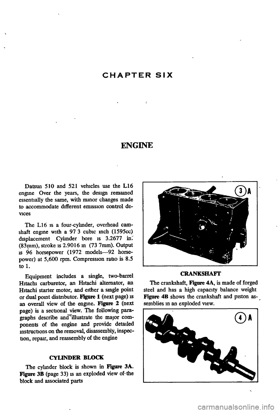
CRANKSHAFI
The
crankshaft
F
JgUre
4A
is
made
of
forged
steel
and
has
a
high
capacity
balance
weight
Figure
4B
shows
the
crankshaft
and
pISton
as
semblies
m
an
exploded
VIew
DA
Page 56 of 252
ENGINE
51
8
Figure
48
shows
the
pm
bemg
mserted
to
make
certam
that
It
can
be
pressed
m
at
room
temperature
by
hand
Piston
pm
clearance
to
piston
pm
should
be
between
0
0003
and
0
0004
m
0008
and
0
01Omm
NOTE
The
piston
pin
IS
fitted
to
the
connecting
rod
with
a
fitting
force
of
from
1
to
3
tons
of
pressure
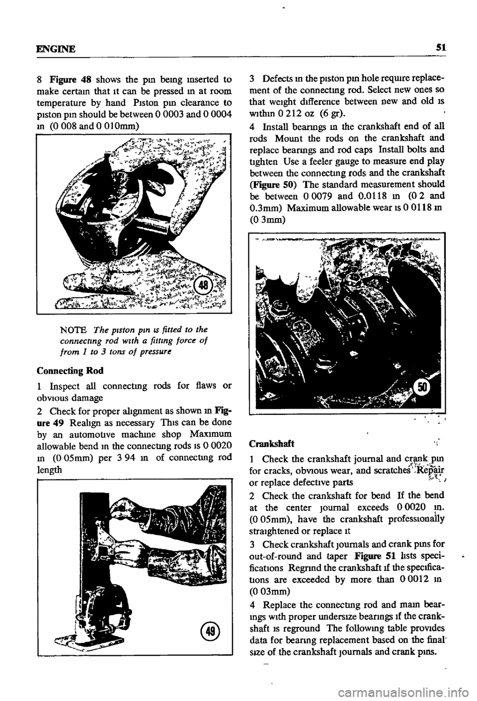
Connecting
Rod
1
Inspect
all
connectmg
rods
for
flaws
or
obVIOUS
damage
2
Check
for
proper
alignment
as
shown
m
Fig
ure
49
RealIgn
as
necessary
ThIS
can
be
done
by
an
automotive
maclune
shop
Maxrmum
allowable
bend
m
the
connecting
rods
IS
0
0020
m
0
05mm
per
3
94
m
of
connecting
rod
length
@
3
Defects
m
the
piston
pm
hole
reqwre
replace
ment
of
the
connectmg
rod
Select
new
ones
so
that
weight
dIfference
between
new
and
old
IS
wlthm
0212
oz
6
gr
4
Install
beanngs
m
the
crankshaft
end
of
all
rods
Mount
the
rods
on
the
crankshaft
and
replace
beanngs
and
rod
caps
Install
bolts
and
tighten
Use
a
feeler
gauge
to
measure
end
play
between
the
connecting
rods
and
the
crankshaft
Figure
50
The
standard
measurement
should
be
between
00079
and
0
0118
m
02
and
0
3mm
Maximum
allowable
wear
IS
00118
m
0
3mm
Crankshaft
1
Check
the
crankshaft
journal
and
crank
pm
1
1
for
cracks
obVIOUS
wear
and
scratcheS
Repair
or
replace
defective
parts
I
2
Check
the
crankshaft
for
bend
If
the
bend
at
the
center
Journal
exceeds
0
0020
m
0
05mm
have
the
crankshaft
prOfeSSIOnally
straightened
or
replace
It
3
Check
crankshaft
Journals
and
crank
pms
for
out
of
round
and
taper
Figure
51
lIsts
speci
fications
Regnnd
the
crankshaft
1f
the
specIfica
tions
are
exceeded
by
more
than
00012
m
0
03mm
4
Replace
the
connecting
rod
and
mam
bear
mgs
With
proper
undersIZe
beanngs
If
the
crank
shaft
IS
reground
The
followmg
table
prOVides
data
for
beanng
replacement
based
on
the
final
sIZe
of
the
crankshaft
Journals
and
crank
pIllS
Page 58 of 252
ENGINE
53
the
mam
beanng
cap
and
the
cyhnder
block
beanng
recess
and
tighten
the
cap
bolts
to
the
proper
torque
WIth
a
torque
wrench
Tig
temng
torque
Main
bearings
506
to
57
8
It
Ib
70to80kg
m
195
to
23
9
It
Ib
27
to3
3
kg
m
Rod
beanngs
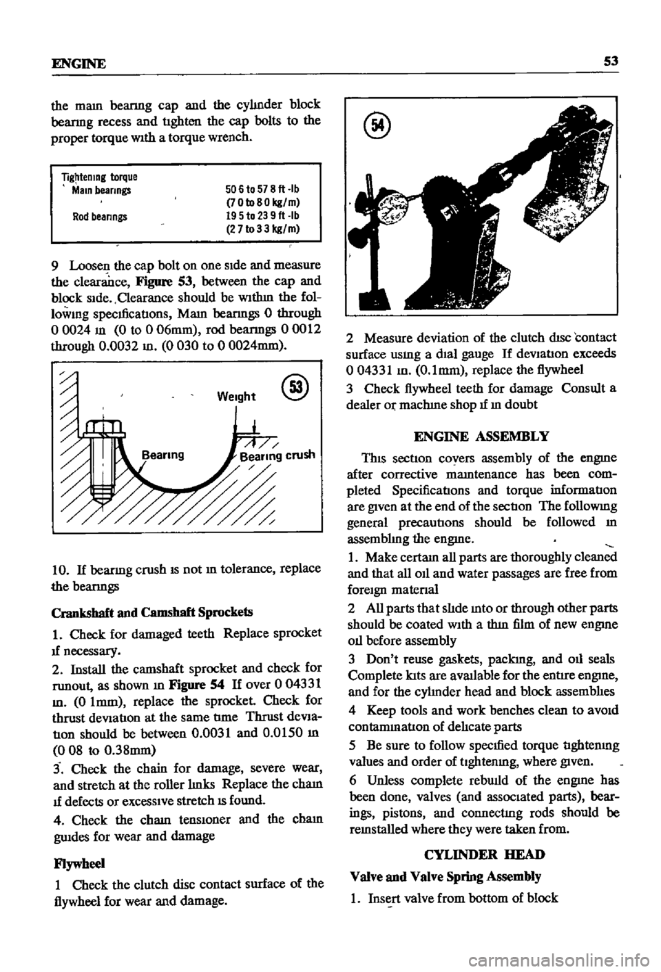
9
Loosen
the
cap
bolt
on
one
Side
and
measure
the
clearance
Figure
53
between
the
cap
and
block
Side
Clearance
should
be
WIthm
the
fol
lowmg
specmcatIons
Mam
beanngs
0
through
o
0024
m
0
to
0
06mm
rod
beanngs
00012
through
0
0032
m
0
030
to
0
0024mm
Weight
@
10
If
beanng
crush
IS
not
m
tolerance
replace
the
beanngs
Crankshaft
and
Camshaft
Sprockets
1
Check
for
damaged
teeth
Replace
sprocket
1f
necessary
2
Install
the
camshaft
sprocket
and
check
for
runout
as
shown
m
Figure
54
If
over
0
04331
m
0
Imm
replace
the
sprocket
Check
for
thrust
deViation
at
the
same
tIme
Thrust
deVia
tIOn
should
be
between
0
0031
and
0
0150
m
008
to
0
38mm
3
Check
the
chain
for
damage
severe
wear
and
stretch
at
the
roller
hnks
Replace
the
cham
1f
defects
or
exceSSIve
stretch
IS
found
4
Check
the
cham
tenslOner
and
the
cham
gwdes
for
wear
and
damage
Flywheel
1
Check
the
clutch
disc
contact
surface
of
the
flywheel
for
wear
and
damage
@
2
Measure
deviation
of
the
clutch
disc
contact
surface
usmg
a
dial
gauge
If
deVIation
exceeds
004331
m
O
lmm
replace
the
flywheel
3
Check
flywheel
teeth
for
damage
Consult
a
dealer
Or
machIne
shop
1f
m
doubt
ENGINE
ASSEMBLY
This
section
covers
assembly
of
the
engme
after
corrective
mamtenance
has
been
com
pleted
SpecificatIons
and
torque
informatIon
are
given
at
the
end
of
the
sectIon
The
followmg
general
precautions
should
be
followed
m
assembhng
the
engme
1
Make
certam
all
parts
are
thoroughly
clean
and
that
all
011
and
water
passages
are
free
from
foreign
matenal
2
All
parts
that
slIde
mto
or
through
other
parts
should
be
coated
With
a
thm
film
of
new
engme
011
before
assembly
3
Don
t
reuse
gaskets
packIng
and
011
seals
Complete
lats
are
aVlUlable
for
the
entire
engme
and
for
the
cyhnder
head
and
block
assemblIes
4
Keep
tools
and
work
benches
clean
to
aVOid
contammatlon
of
delIcate
parts
5
Be
sure
to
follow
specmed
torque
tIghtenmg
values
and
order
of
tlghtenmg
where
given
6
Unless
complete
rebwld
of
the
engme
has
been
done
valves
and
associated
parts
bear
ings
pistons
and
connectIng
rods
should
be
remstalled
where
they
were
taken
from
CYLINDER
HEAD
Valve
and
Valve
Spring
Assembly
1
Insert
valve
from
bottom
of
block
Page 109 of 252
104
CHAPTER
NINE
2
When
one
sIde
shows
low
resIstance
and
the
other
shows
high
resIstance
the
dIode
IS
satls
factory
If
both
sIdes
are
low
there
IS
a
short
CIrCUIt
If
both
sIdes
are
hIgh
there
IS
an
open
CIrcUIt
All
diodes
With
open
or
short
ClrC
ts
must
be
replaced
BRUSH
INSPECTION
1
VIsually
check
the
brushes
for
SIgnS
of
wear
or
damage
If
wear
IS
greater
than
the
wear
lIrmt
shown
in
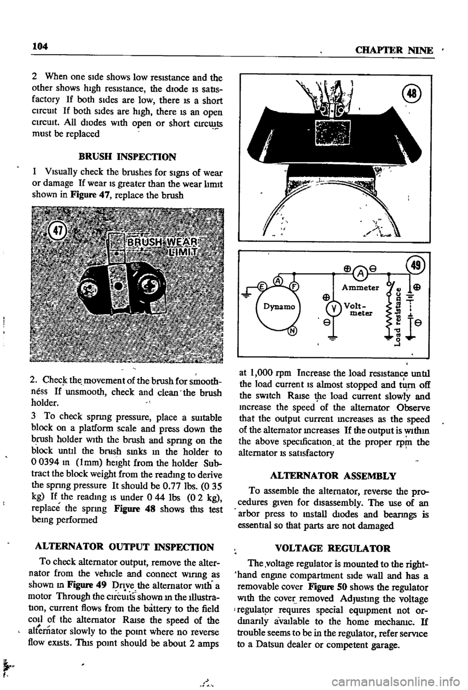
Figure
47
replace
the
brush
2
ChecJ
the
movement
of
the
brush
for
smooth
ness
If
unsmooth
check
and
clean
the
brush
holder
3
To
check
spnng
pressure
place
a
SUItable
block
on
a
platform
scale
and
press
down
the
brush
holder
WIth
the
brush
and
spnng
on
the
block
untIl
the
brush
smks
In
the
holder
to
00394
m
lmm
heIght
from
the
holder
Sub
tract
the
block
weight
from
the
reading
to
derive
the
spnng
pressure
It
should
be
0
77
Ibs
035
kg
If
the
readmg
IS
under
0
44
Ibs
0
2
kg
replace
the
spring
Figure
48
shows
thIS
test
being
performed
ALTERNATOR
OUTPUT
INSPECTION
To
check
alternator
output
remove
the
alter
nator
from
the
vehIcle
and
connect
wumg
as
shown
m
Figure
49
Dq
ve
the
alternator
WIth
a
motor
Through
the
CIrcUItS
shown
m
the
Illustra
tIon
current
flows
from
the
battery
to
the
field
coll
of
the
alternator
RaISe
the
speed
of
the
alternator
slowly
to
the
pOInt
where
no
reverse
flow
eXISts
ThIs
pOInt
should
be
about
2
amps
I
at
1
000
rpm
Increase
the
load
reSIStance
untIl
the
load
current
IS
almost
stopped
and
tlI
rn
off
the
SWItch
RaIse
the
load
current
slowly
and
mcrease
the
speed
of
the
alternator
Observe
that
the
output
current
mcreases
as
the
speed
of
the
alternator
mcreases
If
the
output
is
wlthm
the
above
specmcatIon
at
the
proper
rp
ll
the
alternator
IS
satIsfactory
ALTERNATOR
ASSEMBLY
To
assemble
the
alternator
reverse
the
pro
cedures
given
for
dIsassembly
The
use
of
an
arbor
press
to
mstall
dIodes
and
bearmgs
is
essentIal
so
that
parts
are
not
damaged
VOLTAGE
REGULATOR
The
voltage
regulator
is
mounted
to
the
right
hand
engme
compartment
SIde
wall
and
has
a
removable
cover
Figure
SO
shows
the
regulator
With
the
cover
removed
AdjustIng
the
voltage
regulatpr
reqUIres
special
eqUIpment
not
or
dmanly
avallable
to
the
home
mechanlc
If
trouble
seems
to
be
in
the
regulator
refer
servIce
to
a
Datsun
dealer
or
competent
garage
Page 113 of 252
9
10
4
17
141
18
I
19
21
8
@
1
Distributor
cap
clamp
2
Shaft
assembly
3
Thrust
washer
4
Governor
weight
assembly
5
Governor
spring
6
Cam
assembly
7
Screw
8
Shaft
coupling
assembly
9
Breaker
assembly
10
Contact
POint
assembly
11
Ground
wire
assembly
12
Lead
wire
assembly
13
POlntset
screw
14
Screw
15
Terminal
assembly
16
Rotor
head
assembly
17
Dlstllbutor
cap
assambly
18
Vacuum
control
19
Screw
20
Condensar
21
fixing
plate
22
Bolt
e
OIl
Page 117 of 252

112
Table
1
CHAPTER
NINE
DISTRIBUTOR
SPECIFICATIONS
POint
gap
POint
pressure
Shaft
diameter
lower
part
HOUSing
Inner
diameter
Clearance
between
shaft
and
hOUSing
Ammendment
limit
ot
clearance
Shaft
diameter
upper
part
Cam
Inner
diameter
Clearance
between
shaft
and
cam
Weight
piVOt
dIameter
Weight
hole
dIameter
Clearance
between
piVOt
and
hole
Inches
Millimeters
00177
00217
1
10
143
Ibs
o
4902
0004
0008
o
4902
0
0007
o
00004
00015
00031
03150
0002
0006
03150
0
0006
o
00002
00011
o
1969
00004
00010
01969
0
0007
o
o
0004
0
0018
o
45
0
55
o
50
0
65
kg
1245
010
0020
1245
0
018
o
OlD
O
038
008
8
005
014
8
0
015
o
o
005
0
029
5
010
028
5
0
018
0
001
0046
@
@
r
COllIS
not
pOSSIble
and
It
must
be
replaced
1f
found
defectIve
Inspect
the
connectIons
to
the
coll
to
make
certaIn
they
are
clean
and
tIght
Inspect
the
top
of
the
coIl
for
SIgnS
of
cracks
or
damage
and
replace
1f
necessary
The
Ignluon
COllIS
located
on
the
left
SIde
wall
of
the
engme
compartment
and
is
held
In
place
by
two
screws
and
washers
SPARK
PLUGS
The
followmg
spark
plugs
or
then
equivalent
are
recommended
for
the
L16
engme
ChampIon
No
NlOY
AutolIte
No
AG32A
AC
No
44XL
and
NGK
No
BP
6E
Figure
66
shows
spark
plug
constroctIon
They
should
be
re
RING
CENTER
ELECTRODE
TERMINAL
NUT
IS
r
1
n
f
INSULATOR
moved
penodlcally
and
inspected
for
general
condItIon
cleanmg
or
replacement
anl
regap
pmg
Figure
67
IS
a
senes
of
photos
that
show
the
appearance
of
and
pOSSIble
causes
of
spark
plug
problems
If
the
spark
plugs
are
still
usable
they
should
be
cleaned
thorougWy
with
a
sand
blast
Ing
type
cleaner
The
electrodes
should
then
be
filed
flat
and
the
plug
regapped
The
proper
gap
IS
0
031
to
0035
m
0
8
to
0
9mm
Never
use
a
spark
plug
that
has
a
damaged
or
cracked
msulator
Use
extreme
care
when
remOVIng
and
mstallmg
spark
plugs
to
keep
from
crackIng
the
msulator
Always
bend
the
ground
electrode
when
settmg
the
plug
gap
Never
bend
the
center
electrode