1968 DATSUN 510 transmission oil
[x] Cancel search: transmission oilPage 3 of 252
CON1EN1S
CHAPTER
ONE
GENERAL
INFORMATION
Introduction
Model
Identification
CHAPTER
TWO
PERIODIC
MAINTENANCE
RoutIne
checks
Pen
odic
checks
CHAPTER
THREE
TROUBLESHOOTING
EqUIpment
Starter
ChargIng
system
EngIne
Igmtlon
system
Fuel
system
Exhaust
emIssIon
control
CHAPTER
FOUR
ENGINE
AND
IGNITION
TUNE
UP
EqUIpment
Battery
Spark
plugs
DIstrIbutor
Igmtlon
timIng
CHAPTER
FIVE
ENGINE
LUBRICATION
SYSTEM
Descnptlon
Lubncation
cIrcuIt
SpecIficatiOns
and
dImensIons
EngIne
lubncation
and
maIntenance
Recommended
lubncants
Clutch
TransmIssiOn
Brakes
Steenng
and
suspension
TIre
wear
analysIs
Wheel
balancIng
Idle
speed
and
Idle
mIXture
Dwell
angle
setting
CompressIon
test
Valve
clearance
adjustment
AddlllOnal
checks
Oil
pump
I
6
t
1
4
V
9
t
1
20
27
Page 29 of 252

P
r
OVll
t
ate
I
l
h
l
JlA
ye
I
o
ctg
fI
O
0
I
d
1e
d
c
Ji
uo
JJ
cb
c
s
rlr
I
l
4
c
1
2
24
CHAPTER
FOUR
block
and
should
be
used
as
the
reference
point
m
II
1akmg
adjustments
6
With
a
piece
of
white
chalk
mark
a
hne
down
the
center
of
the
pomter
and
mark
the
timing
groove
on
the
crankshaft
pulley
which
IS
to
be
used
m
tImmg
the
engine
SpecIficatIon
for
tun
ing
reqUIres
trlhmg
at
10
degrees
before
top
dead
center
wluch
would
be
the
fourth
mark
from
the
left
end
of
the
row
of
marks
7
Loosen
the
hold
down
bolt
at
the
base
of
the
dlstnbutor
8
Locate
the
slow
speed
1
Ile
adjustIng
screw
on
the
carburetor
so
that
Ile
speed
can
be
adjusted
whIle
runnmg
Also
locate
throttle
adJustmg
screw
9
Start
engme
and
adjust
speed
With
the
adJust
ing
screws
to
the
readmgs
below
Smgle
pomt
dIStributor
600
rpm
Dual
pomt
trlbutor
700
rpm
10
Alternate
adjustment
of
the
two
screws
untIl
the
smoothest
Idle
at
the
proper
speed
IS
achieved
11
Pomt
the
tlIrung
lIght
at
the
stationary
pomter
When
the
lIght
flashes
the
timmg
mark
n
the
crankshaft
pulley
should
hne
up
With
the
mark
on
the
stationary
pomter
If
It
does
not
exactly
Ime
up
rotate
the
dlstnbutor
gradually
untIl
the
marks
align
mdlcatlng
correct
timmg
12
Shut
off
the
engme
remove
the
tmung
lIght
and
tachometer
tighten
the
hold
down
bolt
on
the
dlStnbutor
and
connect
the
vacuum
advance
hne
to
the
tli
tnbutor
IGNITION
TIMING
IDLE
SPEED
IDLE
MIXTURE
DUAL
POINT
DISTRIBUTOR
ONLY
The
followmg
applies
to
velucles
With
dual
pomt
distributor
and
an
exhaust
emission
con
trol
deVice
If
these
procedures
are
followed
ha
ul
exhaust
emisSion
should
be
below
the
maximum
allowable
level
1
Locate
the
Idle
and
throttle
adJustmg
screws
on
the
carburetor
2
Warm
up
the
engine
thoroughly
3
Connect
tachometer
and
tmung
light
4
Set
the
Id
le
speed
at
700
rpm
With
the
Idle
adjust
screw
5
Adjust
IgnltJ
on
tuning
at
10
degrees
before
top
dead
center
6
Increase
the
speed
of
the
engme
to
2
000
rpm
With
the
accelerator
or
throttle
hnkage
and
hold
for
about
15
seconds
7
Return
to
Idle
for
one
mmute
8
Set
the
engme
to
best
Idle
at
750
rpm
770
rpm
for
automatJ
c
transIDlsslOn
With
the
Idle
and
throttle
adJustmg
screws
9
Re
uce
engme
speed
at
700
rpm
720
rpm
for
automatic
transmission
by
turnmg
the
Idle
adJustmg
screw
clockWise
for
a
leaner
IlliXture
10
Connect
a
wife
lead
between
the
advance
ami
retard
Side
tenrunals
See
Figure
4
Speed
should
drop
from
100
to
150
rpm
11
Check
IgIl1tIon
tmung
With
tImmg
light
It
should
now
be
at
top
d
ad
center
12
If
the
tlmmg
IS
nSJt
correct
stop
the
engme
and
adjust
the
retarded
breaker
pomt
13
Start
the
engme
and
reclieck
ili
tmung
If
l
incorrect
reset
the
retarded
breaker
pomt
until
it
IS
correct
Repeat
s
nece
s
14
Disconnect
the
wife
bet
reen
the
advance
and
retard
termmals
15
Recheck
tmung
It
should
be
10
degrees
before
top
dead
center
16
If
mcorrect
repeat
the
above
procedures
un
tIl
satIsfactory
17
T
he
Idle
speed
of
automatic
transnllsslOn
vehicles
should
be
about
575
rpm
With
the
gear
j
selector
m
the
dhve
poSltlon
c
t
DWELL
ANGLE
SETIING
1
Connect
the
dwell
angle
meter
2
PLoJust
dwell
angle
to
49
to
55
degrees
OMPRESSION
TEST
I
A
compressIOn
test
IS
performed
to
check
for
worn
piston
nngs
or
to
detect
the
cause
of
a
low
speed
miss
Before
undertaking
the
test
el
llmate
the
pOSSibility
of
sticky
valves
by
usmg
one
of
the
oil
additives
deSigned
for
the
purpose
With
valves
free
test
compressIOn
as
follows
1
Run
the
engme
for
15
to
20
mmutes
untIl
normal
operating
temperatures
are
obtained
2
Shut
off
engme
remove
arr
cleaner
and
Page 38 of 252
4l
4111a
78
mml
la78mml
42
4
42
4OIla50mml
t
4544
i
35
45
lIq
D
1
43
45
44
6
1i
45
43
42
41
45
44
46
46
47
8
78mml
I
Tlmmg
Indicator
48
lock
washer
spring
49
Water
Inlet
50
Rubber
cap
51
Rubber
cap
52
Hosa
clamp
53
Inlet
watar
gasket
54
Hex
bolt
55
lock
washer
spring
56
Connector
57
011
filter
cartndge
58
front
engme
cover
59
61
Bloel
cyllndelllner
18
15
58
57
1
Cylinder
block
assembly
2
Main
beanng
bolt
3
Dowel
4
Block
dowel
5
Block
dowel
6
Block
to
transmIssIon
case
dowel
7
Tlmmg
chaIn
covar
dowel
8
Welch
plug
9
Taper
plug
10
Crankcase
011
seal
11
Bearing
011
seal
12
Drain
plug
13
011
pressure
sWitch
14
011
level
gauge
guide
15
Oll
evel
gauga
r1
26
54
25
011
pan
gasket
26
Hax
bolt
27
lock
Sprl
ng
washer
28
011
cooler
hose
clamp
29
Hose
cl
mp
30
Tube
clamp
31
Tube
clamp
32
Clamp
spacer
33
Hex
bolt
34
Washer
35
Crankcase
011
seel
36
Waler
pump
dowel
37
Water
pump
dowel
38
RIght
hand
front
caver
gasket
39
left
hand
front
cover
gasket
40
Hex
bolt
41
Hex
bolt
42
lock
washer
spnng
43
Hex
bolt
44
Hex
bolt
45
Lock
washer
spring
46
Tlmmg
Indicator
47
IndIcator
rivet
22
16
23
Drain
plug
washer
24
Dram
plug
e
l
lIlI
1M
1M
Page 43 of 252
38
CHAPTER
SIX
EMISSION
CONTROL
DEVICES
All
Datsuns
have
a
sealed
type
of
crankcase
emISSion
control
device
and
an
exhaust
emISsion
control
deVice
Models
sold
m
Cahfornla
smce
1970
also
have
an
evaporative
emisSion
control
deVice
An
rmportant
part
of
the
exhaust
control
device
is
the
air
pump
located
at
the
bottom
left
hand
side
of
the
engme
It
IS
dnven
by
a
belt
off
of
the
crankshaft
pulley
and
supphes
air
to
the
exhaust
system
In
1972
an
electric
blower
in
corporated
m
the
air
cleaner
replaced
the
mechanical
pumI
ENGINE
REMOVAL
Expenence
has
shown
It
IS
easier
to
remove
the
engine
and
the
transmission
as
a
smgle
UnIt
than
to
remove
the
engme
alone
Once
the
en
gine
and
transmiSSIon
are
out
of
the
vehIcle
the
tranSmIssion
can
be
detached
from
the
engme
To
remove
the
engme
transmISsion
proceed
as
follows
1
Scribe
ahgnment
marks
on
the
hood
around
the
hmges
ThIS
will
make
remstallatlon
eaSIer
2
Remove
the
two
bolts
that
secure
each
hInge
and
remove
the
hood
It
is
not
necessary
to
re
move
the
hood
support
from
the
engme
firewall
3
DISconnect
the
lower
radIator
hose
from
the
right
hand
SIde
of
the
engine
and
at
the
bottom
of
the
radIator
ThIS
will
pernnt
coolant
to
dram
from
the
engme
and
the
radIator
4
Remove
the
draIn
plugs
from
the
engine
pan
and
translIDSsIon
and
completely
dram
lubn
cants
Into
suitable
contamers
5
DISconnect
the
battery
cables
from
the
bat
tery
loosen
the
two
hold
down
clamps
and
re
move
the
battery
NOTE
The
location
and
number
of
hoses
to
be
removed
from
the
air
cleaner
varies
from
model
to
model
It
IS
normally
easier
to
remove
the
hoses
from
the
sources
rather
than
try
to
dISconnect
them
from
yndemeath
the
air
cleaner
The
1972
model
Will
requlre
dlsconnectlOn
of
the
electrica1
cirCUit
In
the
air
cleaner
system
wing
nut
from
the
top
of
the
air
cleaner
and
remove
the
aIr
cleaner
7
DIsconnect
the
upper
radiator
hose
from
the
radiator
and
the
thermostat
housmg
Remove
the
hose
8
Disconnect
the
two
heater
hoses
from
the
nght
hand
side
of
the
engme
TIe
these
bac
so
they
won
t
interfere
with
removal
of
the
engme
9
Remove
the
radIator
grille
by
unscrewing
all
mountmg
screws
10
Remove
the
four
mounting
screws
holding
the
fan
shield
to
the
backside
of
the
radiator
11
Remove
the
four
mountmg
bolts
holdIng
the
radiator
In
place
In
automatic
tranSmISsion
models
dISconnect
the
two
transnnsslOn
oIl
cooler
lInes
from
the
bottom
of
the
radiator
Pull
the
radiator
straight
up
to
remove
Remove
the
fan
shield
12
Loosen
the
adjustment
and
mounting
bolts
from
the
retamIng
brackets
on
the
alternator
and
air
pump
If
so
eqwpped
The
alternator
is
lo
cated
at
the
bottom
nght
hand
Side
of
the
engme
and
the
air
pump
on
the
lower
left
hand
Side
13
Loosen
tenSIon
on
the
two
dnve
belts
re
move
the
belts
from
the
alternator
and
air
pump
and
then
from
the
fan
pulleys
14
Remove
the
bolts
holdIng
the
fan
and
pulley
to
the
water
pump
assembly
and
remove
the
fan
and
pulley
15
DISconnect
the
fuel
hne
from
the
fuel
pump
16
DIsco
ect
accelerator
control
linkage
and
choke
WIre
at
the
carburetor
17
Disconnect
the
wiring
from
the
starter
motor
alternator
Ignition
coIl
oIl
pressure
switch
and
temperature
transmItting
unit
NOTE
The
following
steps
are
per
formed
from
under
the
car
lack
up
the
front
of
the
car
and
position
stands
under
the
front
support
points
to
proVide
working
room
under
the
vehicle
WARNING
Never
climb
under
a
vehicle
that
is
supported
by
the
lack
only
If
stands
are
not
avflllable
sturdy
wooden
blocks
can
be
U3ed
6
Disconnect
all
hoses
that
lead
to
the
air
cleaner
remove
two
bolts
that
hold
the
air
cleaner
to
its
mountmg
bracket
unscrew
the
18
Remove
two
bolts
holdIng
the
clutch
operat
Ing
cylInder
to
the
flywheel
hOUSIng
shown
m
Page 45 of 252
40
CHAPTER
SIX
be
removed
Hoist
the
engme
off
Its
mounts
and
adjust
the
cham
or
cable
to
tIlt
the
engme
as
shown
in
the
illustration
ContInue
to
raIse
gradually
31
Once
the
engine
and
transmission
are
clear
of
the
vehIcle
lower
them
to
a
swtable
support
or
stand
and
dIsconnect
the
hOISt
32
The
transmISSIon
can
now
be
freed
by
re
movmg
the
bolts
holdIng
the
clutch
assembly
to
the
flywheel
housing
and
movmg
the
clutch
assembly
back
to
dIsengage
the
dnve
shaft
splmes
33
Witlltlie
engIne
removed
carefiillyinspect
the
mountIng
Insulators
for
SIgnS
of
damage
or
detenoratIon
Replace
them
1f
necessary
ENGINE
DISASSEMBLY
ThIS
sectIon
covers
dIsassembly
of
the
engine
once
It
has
been
removed
from
the
vehIcle
All
steps
would
be
followed
for
a
complete
engme
overhaul
But
smce
many
of
the
procedures
can
be
done
WIthout
removing
the
engIne
from
the
velucle
a
complete
course
of
actIon
should
be
decided
on
before
needless
removal
and
ms
assembly
Mount
the
engme
on
a
stand
or
other
sUItable
work
surface
before
msassembly
Thoroughly
clean
the
extenor
WIth
steam
or
solvent
CAUTION
Remove
the
alternator
starter
motor
carburetor
and
dIStributor
from
the
engine
before
cleaning
to
prevent
damage
Once
clean
mspect
the
engme
for
SIgnS
of
damage
or
mlssmg
parts
cracks
or
accumulated
rust
on
the
block
especIally
around
the
soft
plugs
cracks
In
the
clutch
housing
and
dents
or
cracks
In
the
oil
pan
DISassemble
as
follows
Alternator
Removal
1
Figure
14
shows
the
positIon
of
the
alternator
on
the
engme
and
a
VIew
of
the
alternator
mountIng
parts
Remove
the
two
bolts
lock
washers
and
shmls
holding
the
alternator
to
the
adjustIng
bar
and
the
adjustIng
bar
to
the
engme
block
2
Remove
the
two
bolts
and
lockwashers
hold
ing
the
alternator
to
lower
mounting
bracket
3
Remove
the
alternator
and
mountmg
brack
ets
Starter
Motor
Removal
1
Remove
two
mountIng
bolts
and
lockwashers
holdmg
starter
motor
to
clutch
housmg
2
Pull
starter
assembly
toward
front
of
engme
and
remove
Distributor
Removal
1
Scnbe
ahgnment
marks
on
the
mstrlbutor
shaft
tl
ie
ihsthDutor
mountmg
oracket
anihlfe
front
cover
so
that
the
dIStnbutor
can
be
re
placed
accurately
later
2
Remove
two
bolts
and
lockwashers
holdIng
the
dlstnbutor
mountmg
housmg
to
the
front
cover
3
Pull
up
on
the
dlstnbutor
and
remove
it
as
a
unit
Carburetor
Removal
1
Remove
the
four
nuts
and
lockwashers
join
mg
the
carburetor
and
mtake
manifold
then
remove
carburetor
Oil
Pump
Removal
1
Remove
the
four
mountIng
bolts
and
lock
washers
2
WIthdraw
the
011
pump
assembly
from
tht
front
cover
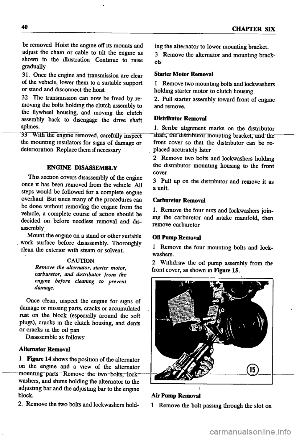
as
shown
m
Figure
15
@
Air
Pump
Removal
1
Remove
the
bolt
passmg
through
the
slot
on
Page 48 of 252
ENGINE
43
@
0
00
o
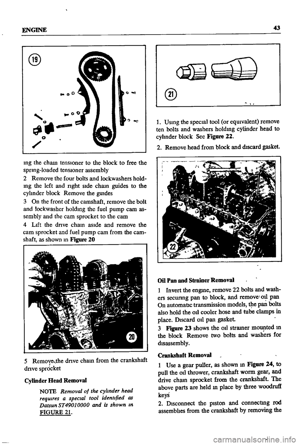
mg
the
cham
tenslOner
to
the
block
to
free
the
sprIng
loaded
tenslOner
assembly
2
Remove
the
four
bolts
and
lockwashers
hold
mg
the
left
and
rIght
sIde
cham
guides
to
the
cylmder
block
Remove
the
guIdes
3
On
the
front
of
the
camshaft
remove
the
bolt
and
lockwasher
holdIng
the
fuel
pump
cam
as
sembly
and
the
eam
sprocket
to
the
eam
4
LIft
the
drIve
chaIn
asIde
and
remove
the
earn
sprocket
and
fuel
pump
cam
from
the
cam
shaft
as
shown
In
Figure
20
5
Remove
the
dnve
cham
from
the
crankshaft
drIve
spr6cket
Cylinder
Head
Removal
NOTE
Removal
of
the
cylinder
head
requires
a
special
tool
identified
as
DatsunST49010000
and
is
shown
In
FIGURE
21
@
I
USIng
the
specIal
tool
or
eqUIvalent
remove
ten
bolts
and
washers
holdIng
cylinder
head
to
cyhnder
block
See
Figure
22
2
Remove
head
from
block
and
dtscard
gasket
Oil
Pan
and
Strainer
Removal
I
Invert
the
engme
remove
22
bolts
and
wash
ers
secunng
pan
to
block
and
remove
011
pan
On
automatIc
transmission
models
tpe
pan
bolts
also
hold
the
oIl
cooler
hose
and
tube
clamps
in
place
DISCard
011
pan
gasket
3
Figure
23
shows
the
oIl
stramer
mOlJ
lted
m
the
block
Remove
two
bolts
and
washers
for
dISassembly
Crankshaft
Removal
I
Use
a
gear
puller
as
shown
III
Figure
24
to
pull
the
oIl
thrower
crankshaft
worm
gear
and
drive
cham
sprocket
from
the
crankshaft
The
above
parts
are
held
In
place
by
three
woodruff
keyS
2
DISconnect
the
pIston
and
connectrng
rod
assemblIes
from
the
crankshaft
by
removing
the
Page 64 of 252

ENGINE
59
2
Coat
the
pan
gasket
on
both
sides
With
gasket
compound
and
attach
the
oil
pan
to
the
cyhnder
block
Torque
as
specIfied
Manifold
and
Carburetor
Installation
1
Install
the
mtake
and
exhaust
manIfolds
WIth
associated
gasket
to
the
cylmder
head
2
Mount
the
carburetor
and
gasket
to
the
mtake
manIfold
2
Adjust
all
mtake
and
exhaust
valves
to
the
specIfied
clearance
for
a
cold
engme
Clutch
Assembly
Installation
CAUTION
Take
extreme
care
not
to
get
grease
or
011
on
the
clutch
or
flywheel
frlc
hon
contact
surfaces
1
Place
the
clutch
disc
assembly
on
the
flywheel
With
the
longer
chamfered
splmed
end
of
the
dISC
toward
the
transmISSion
2
Visually
align
or
use
a
dummy
splmed
dnve
shaft
to
ahgn
the
diSC
assembly
With
the
flywheel
pilot
beanng
3
Install
and
tighten
the
SIX
bolts
holdmg
the
clutch
cover
assembly
to
the
flywheel
Tighten
the
bolts
a
turn
each
tune
by
diagonal
pattern
until
they
are
tight
Tlghtenmg
torque
should
be
174
to
188ft
lbs
24
to
2
6
kg
m
NOTE
There
are
two
dowels
on
the
flywheel
to
locate
the
clutch
cover
4
Remove
dummy
shaft
If
used
after
the
above
bolts
are
fully
tightened
5
Refit
the
release
bearing
and
translI11Ssion
case
Miscellaneous
Installation
1
Connect
the
fuel
hose
on
the
front
part
of
the
engme
to
the
fuel
pump
and
to
the
carburetor
2
Gap
the
spark
plugs
and
mstall
them
usmg
new
gaskets
3
Coat
the
rocker
arm
cover
gasket
With
sealer
and
position
It
on
the
cylmder
head
4
Install
the
rocker
arm
cover
and
tighten
the
two
thumb
screws
that
hold
it
m
place
5
Install
distrIbutor
makmg
certam
that
the
notch
on
the
distributor
shaft
assembly
mates
With
the
drive
spmdle
Ahgn
the
location
marks
made
dunng
disassembly
so
that
the
distrIbutor
is
positioned
as
before
6
Install
and
tighten
the
bolts
which
hold
the
dIStributor
to
the
front
cover
7
Install
pomts
condenser
and
rotor
8
Replace
distrIbutor
cap
and
attach
spark
plug
Wires
m
the
correct
sequence
Make
certain
that
all
wires
are
firmly
seated
m
the
distrIbutor
cap
and
attached
securely
to
the
spark
plugs
9
HOISt
the
engme
assembly
from
the
work
stand
10
Install
the
alternator
bracket
alternator
and
engme
mounts
to
the
block
11
Install
the
IgnItIon
coil
oil
filter
oil
pressure
SWitch
dipstick
and
water
drain
plug
12
Connect
the
vacuum
Ime
between
the
dis
trIbutor
and
carburetor
13
Connect
the
transIDlSSlOn
to
the
engine
prior
to
mstallatIon
m
the
vehicle
Engine
Installation
Installation
is
the
reverse
of
the
procedures
followed
m
removal
Be
certaIn
thatlall
battery
connections
are
made
that
water
hoses
are
se
cured
wmng
IS
connected
properly
and
that
all
required
bolts
and
mounts
are
mstalled
and
tightened
Replace
the
radiator
fan
belts
and
radiator
shroud
Fill
the
engme
With
the
proper
grade
of
oil
and
the
radiator
With
recommended
coolant
Install
the
hood
to
the
hInges
according
to
the
marks
made
dUrIng
removal
SERVICE
DATA
AND
SPECIFICATIONS
Table
1
covers
servIce
data
and
engme
Speci
fications
Page 124 of 252
EMISSION
CONTROL
S
IS
TEM
SEDAN
AND
SlATION
YfAGON
Yfl
tH
AUTOMATIC
TRANSMISSION
TO
DISTRIBUTOR
IGNITION
COIL
IGNITION
SWITCH
tnE
RETARDED
BREAKER
POINT
1
SPEED
SWITCH
THROTTLE
SWITCH
SWITCH
DETECTING
WIDE
OPEN
THROTTLE
POSITION
SWITCH
DETECTING
CLOSE
THROTTLE
POS
iION
Q
Z
S
e
l