1968 DATSUN 510 transmission oil
[x] Cancel search: transmission oilPage 134 of 252
CLUTCH
TRANSMISSION
AND
DRIVESHAFI
129
scratches
on
the
pressure
plate
may
be
removed
with
crocus
cloth
If
the
source
of
clutch
trouble
IS
still
not
evl
dent
take
the
pressure
plate
and
disc
to
a
compe
tent
garage
to
check
the
pressure
plate
finger
release
height
and
nmout
Never
attempt
to
ad
just
the
fingers
or
dismantle
the
pressure
plate
Without
proper
tools
and
experience
Check
the
release
bearing
by
holdmg
the
Inner
race
and
rotatmg
the
outer
race
With
hght
pres
sure
applied
If
the
bearing
is
rough
or
noisy
replace
it
CAUTION
Never
clean
the
release
bearing
In
solvent
It
IS
prelubriCflted
at
the
fac
tory
Simply
wipe
with
a
Unt
free
cloth
If
the
release
bearing
shows
any
signs
of
loss
of
lubncant
install
a
new
bearing
Replace
the
sleev
lu
SignS
of
wear
are
evident
Clutch
Reassembly
1
Be
sure
your
hands
are
clean
for
the
initIal
assembly
2
Inspect
the
clutch
facings
pressure
plate
and
flywheel
to
be
sure
they
are
free
from
grease
oil
and
other
foreIgn
material
3
TIghtly
fit
release
bearmg
onto
the
bearing
sleeve
When
beanng
IS
mstalled
turn
bearmg
With
a
finger
to
make
sure
It
operates
smoothly
4
Apply
multI
purpose
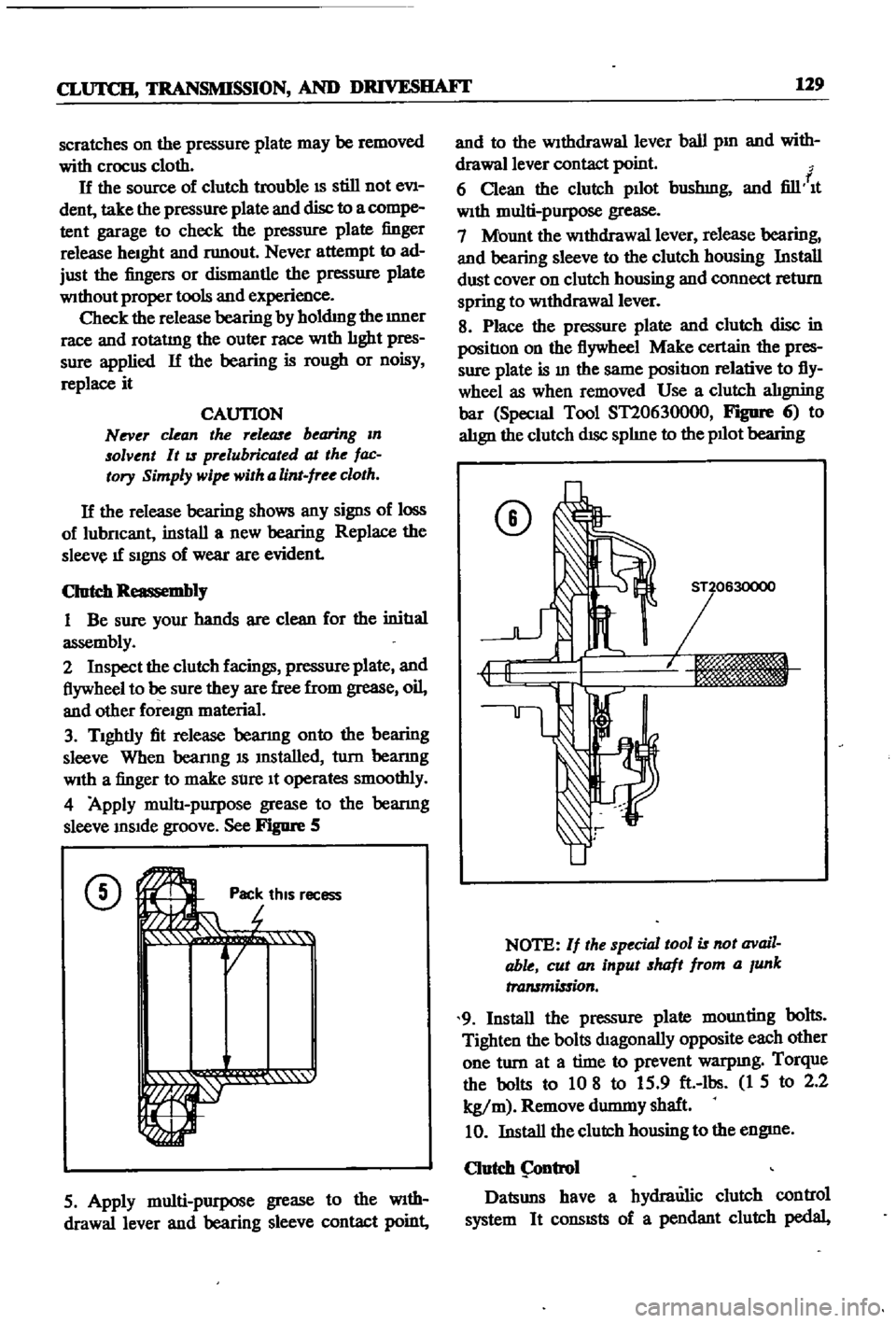
grease
to
the
bearmg
sleeve
InSIde
groove
See
Figure
5
CD
Ji
rot
Pac
thiS
r
r
r
1
1i
QI
ecess
5
Apply
multi
purpose
grease
to
the
WIth
drawallever
and
bearing
sleeve
contact
point
and
to
the
Withdrawal
lever
ball
pm
and
with
drawallever
contact
point
f
6
Clean
the
clutch
pllot
bushmg
and
fill
It
With
multi
purpose
grease
7
Mount
the
WithdraWal
lever
release
bearing
and
bearing
sleeve
to
the
clutch
housing
Install
dust
cover
on
clutch
housing
and
connect
return
spring
to
WithdraWal
lever
8
Place
the
pressure
plate
and
clutch
disc
in
positIon
on
the
flywheel
Make
certain
the
pres
sure
plate
is
In
the
same
positIon
relative
to
fly
wheel
as
when
removed
Use
a
clutch
alIgning
bar
Special
Tool
ST20630000
FIgDfe
6
to
alIgn
the
clutch
dISc
splIne
to
the
pllot
bearing
CD
NOTE
If
the
special
tool
is
not
avail
able
cut
an
input
shaft
from
a
Junk
transmission
9
Install
the
pressure
plate
mounting
bolts
Tighten
the
bolts
dIagonally
opposite
each
other
one
turn
at
a
time
to
prevent
warpmg
Torque
the
bolts
to
10
8
to
15
9
ft
lbs
1
5
to
2
2
kg
m
Remove
durmny
shaft
10
Install
the
clutch
housing
to
the
engme
Clutch
ntrol
Datsuns
have
a
hydraulic
clutch
control
system
It
consISts
of
a
pendant
clutch
pedal
Page 147 of 252
142
CHAPTER
ELEVEN
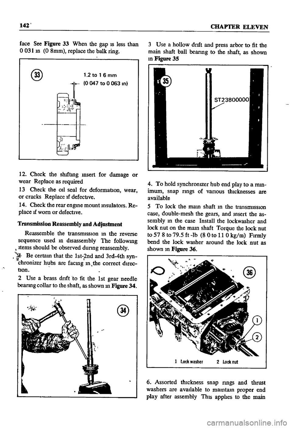
face
See
Figure
33
When
the
gap
IS
less
than
o
031
m
0
8mm
replace
the
balk
ring
@
1
2
to
1
6
mm
0047
to
0
063
In
12
Check
the
sh1fnng
msert
for
damage
or
wear
Replace
as
required
13
Check
the
OIl
seal
for
deformatIon
wear
or
cracks
Replace
1f
defectIve
14
Check
the
rear
engme
mount
Insulators
Re
place
1f
worn
or
defectIve
Transmission
Reassembly
and
Adjustment
Reassemble
the
transmISSIon
In
the
reverse
sequence
used
ill
dIsassembly
The
followmg
Items
should
be
observed
dunng
reassembly
1
Be
certaIn
that
the
1st
2nd
and
3rd
4th
syn
chronizer
hubs
are
facmg
ill
the
correct
dIrec
tIon
2
Use
a
brass
dnft
to
fit
the
1
st
gear
needle
bearlOg
collar
to
the
shaft
as
shown
In
Figure
34
il
@
3
Use
a
hollow
dnft
and
press
arbor
to
fit
the
main
shaft
ball
bearmg
to
the
shaft
as
shown
10
Figure
35
4
To
hold
synchronIZer
hub
end
play
to
a
mm
imum
snap
rmgs
of
vanous
thIcknesses
are
available
5
To
lock
the
malO
shaft
m
the
transrmSSlOn
case
double
mesh
the
gears
and
msert
the
as
sembly
10
the
case
Install
the
lockwasher
and
lock
nut
on
the
mam
shaft
Torque
the
lock
nut
to
57
8
to
79
5
ft
lb
8
0
to
11
0
kg
m
Fumly
bend
the
lock
washer
around
the
lock
nut
as
shown
In
Figure
36
1
lock
washer
2
Lock
nut
6
Assorted
thIckness
snap
nngs
and
thrust
washers
are
avallable
to
malOtam
proper
end
play
after
assembly
ThIS
applIes
to
the
main
Page 151 of 252
146
CHAPTER
ELEVEN
o
i
fij@
0
@
7
B@
I
l
I
L
J
1
Before
disassembly
clean
all
parts
and
mark
locations
2
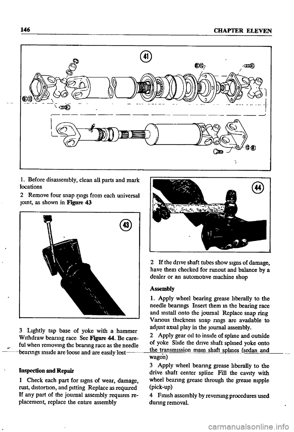
Remove
four
snap
gs
from
each
universal
JOInt
as
shown
in
Figure
43
@
3
LIghtly
tap
base
of
yoke
with
a
hammer
WIthdraw
beanng
race
See
Figure
44
Be
care
ful
when
remoVIng
the
bearmg
race
as
the
needle
bearmgs
InSIde
are
loose
and
are
easlly
lost
Inspection
and
Repair
1
Check
each
part
for
SIgnS
of
wear
damage
nlSt
dIStortIOn
and
pItting
Replace
as
reqUIred
If
any
part
of
the
journal
assembly
reqUIres
re
placement
replace
the
entIre
assembly
am
@
t
@
2
If
the
dnve
shaft
tubes
show
SIgnS
of
damage
have
them
checked
for
nmout
and
balance
by
a
dealer
or
an
automotIve
machine
shop
Assembly
1
Apply
wheel
bearing
grease
lIberally
to
the
needle
bearmgs
Insert
them
m
the
bearing
face
and
mstall
onto
the
journal
Replace
snap
ring
Vanous
thIckness
snap
nngs
are
avatlable
to
adjust
aXIal
play
in
the
Journal
assembly
2
Apply
gear
Oil
to
inSIde
of
splIne
and
outside
of
yoke
SlIde
the
dnve
shaft
splIned
yoke
onto
the
transmIssion
maIn
shaft
Sl1hnes
sedan
and
wagon
3
Apply
wheel
bearmg
grease
lIberally
to
the
drive
shaft
center
spline
Fill
the
caVIty
with
wheel
bearmg
grease
through
the
grease
mpple
pick
up
4
FJ
nlSh
assembly
by
reversIng
procedures
used
durmg
removal
Page 152 of 252
CLUTCH
TRANSMISSION
AND
DRIVESHAFI
147
SERVICE
DATA
AND
SPECIFICATIONS
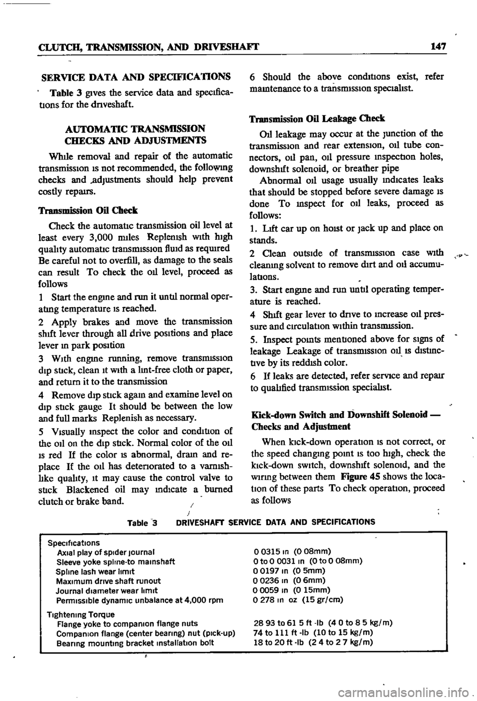
Table
3
gives
the
service
data
and
specIfica
tIons
for
the
dnveshaft
AUTOMATIC
TRANSMISSION
CHECKS
AND
ADJUSTMENTS
Whlle
removal
and
repair
of
the
automatic
transmisSIOn
IS
not
recommended
the
follo
VlIlg
checks
and
adjustments
should
help
prevent
costly
repatrs
Transmission
Oil
Check
Check
the
automatIc
transmission
oil
level
at
least
every
3
000
mlles
Replemsh
With
hIgh
qualIty
automatIc
transmISSIon
flUId
as
reqUIred
Be
careful
not
to
overfill
as
damage
to
the
seals
can
result
To
check
the
011
level
proceed
as
follows
1
Start
the
engme
and
nm
it
untIl
normal
oper
atrng
temperature
IS
reached
2
Apply
brakes
and
move
the
transmission
shut
lever
through
all
drive
pOSItions
and
place
lever
In
park
position
3
WIth
engme
running
remove
tranSmISSIon
dIp
StIck
clean
It
WIth
a
lInt
free
cloth
or
paper
and
return
it
to
the
transmission
4
Remove
dIp
stIck
agam
and
examine
level
on
dIp
stIck
gauge
It
should
be
between
the
low
and
full
marks
Replenish
as
necessary
5
VIsually
InSpect
the
color
and
condItIon
of
the
OIl
on
the
dIp
stIck
Normal
color
of
the
OIl
IS
red
If
the
color
IS
abnormal
dram
and
re
place
If
the
011
has
detenorated
to
a
vamlsh
lIke
qualIty
It
may
cause
the
control
valve
to
stIck
Blackened
oil
may
mdlcate
a
burned
clutch
or
brake
band
6
Should
the
above
condItIons
exist
refer
mamtenance
to
a
transmISSIon
specIalIst
Transmission
Oil
Leakage
Check
011
leakage
may
occur
at
the
Junction
of
the
transmissIon
and
rear
extensIon
011
tube
con
nectors
011
pan
OIl
pressure
mspectIon
holes
downshIft
solenoid
or
breather
pipe
Abnormal
OIl
usage
usually
mdlcates
leaks
that
should
be
stopped
before
severe
damage
IS
done
To
mspect
for
011
leaks
proceed
as
follows
1
LIft
car
up
on
hOISt
or
Jack
up
and
place
on
stands
2
Clean
outsIde
of
transmISSIon
case
With
cleanIng
solvent
to
remove
dIrt
and
011
accumu
latIons
3
Start
engme
and
nm
untIl
operating
temper
ature
is
reached
4
ShIft
gear
lever
to
dnve
to
Increase
011
pres
sure
and
CIrculatIon
WIthin
tranSmISsion
5
Inspect
pOInts
mentIoned
above
for
SIgnS
of
leakage
Leakage
of
transrmSSIOn
011
IS
dIStrnC
tIve
by
its
reddISh
color
6
If
leaks
are
detected
refer
servIce
and
reparr
to
qualIfied
transrmssion
specialISt
Kick
down
Switch
and
Downshift
Solenoid
Checks
and
Adjustment
When
ktck
down
operatIon
IS
not
correct
or
the
speed
changmg
pomt
IS
too
high
check
the
klck
down
SWItch
downshIft
solenOId
and
the
wlDng
between
them
Figure
45
shows
the
loca
tIOn
of
these
parts
To
check
operatIon
proceed
as
follows
Table
3
J
DRIVESHAFT
SERVICE
DATA
AND
SPECIFICATIONS
SpeCifications
Axial
play
of
spider
Journal
Sleeve
yoke
spltne
to
malnshaft
Spline
lash
wear
Itmlt
MaXimum
drive
shaft
runout
Journal
diameter
wear
limit
Penmlsslble
dynamiC
unbalance
at
4
000
rpm
Tightening
Torque
Flange
yoke
to
compaRlon
flange
nuts
CompaRlon
flange
center
bearing
nut
pick
up
Bearing
mounting
bracket
installation
bolt
00315
In
008mm
OtoO
0031
In
OtoO
08mm
00197
In
0
5mm
00236
In
06mm
00059
In
0
15mm
0278
In
oz
15
gr
cm
2893
to
615ft
Ib
40
to
8
5
kg
m
74
to
111
ft
Ib
10
to
15
kg
m
18
to
20
ft
Ib
24
to
2
7
kg
m
Page 245 of 252
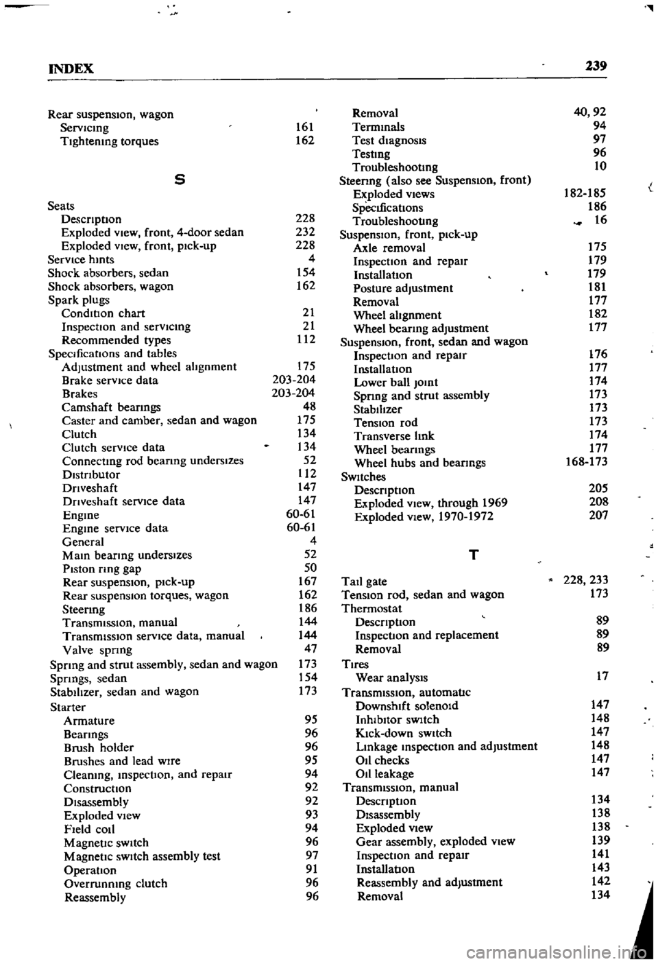
l
INDEX
239
Rear
suspensIOn
wagon
Removal
40
92
Servlcmg
161
Termmals
94
Tightening
torques
162
Test
diagnosIs
97
Testmg
96
Troubleshootmg
10
5
Steenng
also
see
Suspension
front
I
Exploded
views
182
185
L
Seats
SpecIfications
186
DescnptIon
228
Troubleshooting
16
Exploded
View
front
4
door
sedan
232
SuspensIOn
front
pick
up
Exploded
VIew
front
pick
up
228
Axle
removal
175
Service
hmts
4
Inspection
and
repair
179
Shock
absorbers
sedan
154
Installation
179
Shock
absorbers
wagon
162
Posture
adjustment
181
Spark
plugs
Removal
177
CondlllOn
chart
21
Wheel
abgnment
182
InspectIon
and
servlcmg
21
Wheel
bearmg
adjustment
177
Recommended
types
112
Suspension
front
sedan
and
wagon
SpecificatIOns
and
tables
Inspection
and
repair
176
Adjustment
and
wheel
alignment
175
InstallatIOn
177
Brake
service
data
203
204
Lower
ball
Jomt
174
Brakes
203
204
Spnng
and
strut
assembly
173
Camshaft
beanngs
48
Stabilizer
173
Caster
and
camber
sedan
and
wagon
175
TenSIOn
rod
173
Clutch
134
Transverse
bnk
174
Clutch
service
data
134
Wheel
beanngs
177
Connectmg
rod
beanng
underslzes
52
Wheel
hubs
and
bearmgs
168
173
Dlstnbutor
112
SWItches
Dnveshaft
147
DescnptIon
205
Dnveshaft
service
dala
147
Exploded
View
through
1969
208
Engme
60
61
Exploded
view
1970
1972
207
Engme
service
data
60
61
General
4
Mam
bearmg
underslzes
52
T
Piston
rmg
gap
50
Rear
suspenSIOn
pick
up
167
Tail
gate
228
233
Rear
suspensIOn
torques
wagon
162
TenSIOn
rod
sedan
and
wagon
173
Steermg
186
Thermostat
TransmiSSion
manual
144
DescnptIon
89
TransmiSSion
service
data
manual
144
Inspection
and
replacement
89
Valve
spnng
47
Removal
89
Sprmg
and
strut
assembly
sedan
and
wagon
173
Tires
Spnngs
sedan
154
Wear
analYSIS
17
Stabilizer
sedan
and
wagon
173
TransmiSSion
automatic
Starter
Downshift
solenOid
147
Armature
95
Inhlbllor
SWItch
148
Beanngs
96
Kick
down
SWitch
147
Brush
holder
96
Lmkage
mspectIon
and
adjustment
148
Brushes
and
lead
WIre
95
011
checks
147
Cleaning
mspectIon
and
repair
94
Oil
leakage
147
Construcllon
92
TransmiSSion
manual
Disassembly
92
DescnptIon
134
Exploded
View
93
Disassembly
138
Field
COIl
94
Exploded
view
138
Magnetic
SWItch
96
Gear
assembly
exploded
view
139
Magnetic
SWItch
assembly
test
97
Inspection
and
repair
141
Operation
91
Installation
143
Overrunnmg
clutch
96
Reassembly
and
adjustment
142
Reassembly
96
Removal
134