1968 DATSUN 510 seats
[x] Cancel search: seatsPage 5 of 252
CHAPTER
TWELVE
DIFFERENTIAL
REAR
AXLE
AND
REAR
SUSPENSION
149
DIfferentIal
Rear
axle
and
suspension
Codspnng
Shock
absorber
Rear
suspensIOn
arm
Rear
axle
shaft
Wheel
beanngs
Seals
Rear
spnng
Axle
case
SpecificatIons
CHAPTER
THIRTEEN
FRONT
AXLE
FRONT
SUSPENSION
AND
STEERING
168
Wheel
hub
and
bearmg
StabilIzer
TenSion
rod
Spnng
and
strut
assembly
Transverse
lInk
Lower
ball
Jomt
Front
suspension
adjustment
Wheel
alignment
Posture
adJustment
Steenng
system
SpeCificatIons
CHAPTER
FOURTEEN
BRAKES
187
Brake
pedal
Master
cylInder
Front
diSC
brakes
Rear
brakes
Front
drum
brakes
Wheel
cylInders
Brake
system
bleedIng
Handbrake
Service
data
and
speCificatIons
CHAPTER
FIFTEEN
BODY
ELECTRICAL
SYSTEM
Wmng
SWitches
and
fuses
Instrument
meters
and
panels
Heater
205
Wmdshleld
wipers
Wmdslueld
washers
Headlamps
WIrIng
diagrams
CHAPTER
SIXTEEN
BODY
223
Front
body
trIm
Bumpers
Hood
lock
control
Doors
Door
locks
and
regulators
Trunk
lId
and
rear
bumper
Seats
Tad
gate
INDEX
235
I
Page 39 of 252
34
CHAPTER
SIX
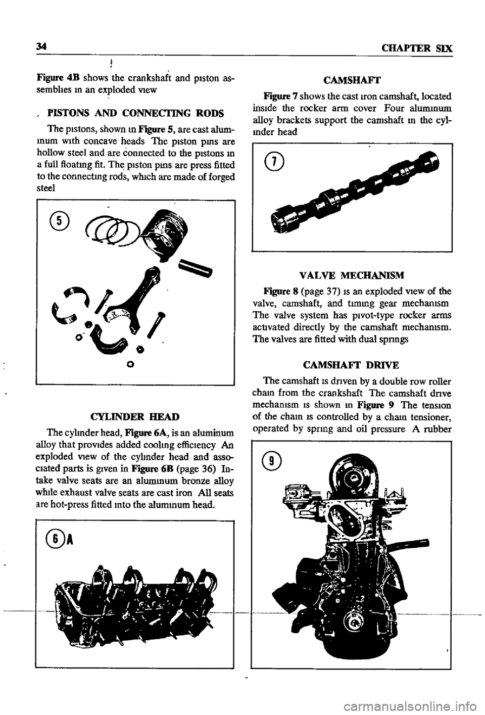
Figure
4B
shows
the
crankshaft
and
piston
as
semblIes
m
an
exploded
VIew
PISTONS
AND
CONNECTING
RODS
The
pistons
shown
m
Figure
5
are
cast
alum
mum
With
concave
heads
The
piston
pms
are
hollow
steel
and
are
connected
to
the
pistons
m
a
full
floatmg
fit
Th
piston
pms
are
press
fitted
to
the
connectIng
rods
which
are
made
of
forged
steel
CD
l
o
o
o
CYLINDER
HEAD
The
cylInder
head
Figure
6A
is
an
aluminum
alloy
that
provides
added
coolmg
effiCiency
An
exploded
VIew
of
the
cylInder
head
and
asso
ciated
parts
is
given
in
Figure
6B
page
36
In
take
valve
seats
are
an
alummum
bronze
alloy
while
exhaust
valve
seats
are
cast
iron
All
seats
are
hot
press
fitted
mto
the
alummum
head
0A
CAMSHAFr
Figure
7
shows
the
cast
Iron
camshaft
located
inSide
the
rocker
arm
cover
Four
alummum
alloy
brackets
support
the
camshaft
m
the
cyl
mder
head
CD
VALVE
MECHANISM
Figure
8
page
37
IS
an
exploded
VIew
of
the
valve
camshaft
and
t1mmg
gear
mechanism
The
valve
system
has
pivot
type
rocker
arms
activated
directly
by
the
camshaft
mechanIsm
The
valves
are
fitted
with
dual
spnngs
CAMSHAFI
DRIVE
The
camshaft
IS
dnven
by
a
double
row
roller
cham
from
the
crankshaft
The
camshaft
dnve
mechanIsm
IS
shown
m
Figure
9
The
tensIOn
of
the
cham
IS
controlled
by
a
cham
tensioner
operated
by
spnng
and
oil
pressure
A
rubber
CD
Page 195 of 252
190
CHAPTER
FOURTEEN
Master
Cylinder
Assembly
and
Installation
I
Assemble
the
master
cyhnder
m
the
reverse
order
of
dIsassembly
2
Pnor
to
assembly
soak
piston
cap
m
brake
flwd
Install
piston
so
that
It
seats
firmly
on
the
piston
cup
3
Coat
the
cyhnder
bore
and
pISton
assemblies
With
clean
brake
flwd
before
assembly
4
When
assembly
IS
complete
mount
master
cylmder
on
dash
wall
and
hook
connecting
rod
to
brake
pedal
Replace
return
sprmg
Fill
the
reservOir
With
clean
brake
flUid
5
If
aIr
has
seeped
mto
the
brake
Imes
bleed
the
brakes
as
descnbed
later
m
thIS
chapter
FRONT
DISC
BRAKES
SEDAN
AND
WAGON
Brake
Pad
Replacement
Pad
wear
should
be
checked
every
4
000
nuIes
Clearance
between
the
pad
and
the
rotor
IS
adjusted
automatIcally
and
therefore
IS
not
a
wear
mdlcator
Pad
thiCknesS
IS
checked
by
re
movmg
the
antI
rattle
clJp
When
the
pad
hning
becomes
worn
to
0
04
Imm
replace
all
pads
on
the
front
wheels
I
Remove
the
hub
cap
loosen
the
hub
nuts
jack
up
the
vehicle
support
with
stands
and
remove
the
front
wheels
2
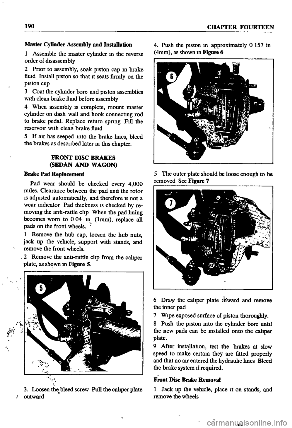
Remove
the
antI
rattle
clJp
from
the
caliper
plate
as
shown
m
Figure
S
jty
3
Loosen
the
bleed
screw
Pull
the
calJper
plate
outward
4
Push
the
pISton
m
approximately
0
157
in
4mm
as
shown
m
Figure
6
5
The
outer
plate
should
be
loose
enough
to
be
removed
See
Figure
7
6
Dra
y
the
calJper
plate
rlfward
and
remove
the
inner
pad
7
Wipe
exposed
surface
of
piston
thoroughly
8
Push
the
piston
mto
the
cyhnder
bore
untJI
the
new
pads
can
be
mstalled
onto
the
calJper
plate
9
After
instl
llatIon
test
the
brakes
at
slow
speed
to
make
certam
they
are
fitted
properly
and
that
no
au
entered
the
hydraul1c
hnes
Bleed
the
brake
system
If
required
Front
Disc
Brake
Removal
I
Jack
up
the
vehicle
place
It
on
stands
and
remove
the
wheels
P
Page 230 of 252
CHAPTER
SIXTEEN
ThIS
chapter
provides
infOrnl8tion
and
pro
cedures
for
removal
adJustment
and
or
re
placement
of
various
body
components
in
cluded
are
the
hood
front
trinl
doors
seats
locks
bumpers
tail
gates
and
door
and
window
controls
The
illustrations
given
are
typical
of
the
sedan
the
station
wagon
IS
similar
Details
on
the
pick
up
are
given
in
separate
illustrations
Other
body
repairs
require
special
knowledge
CD
L
BODY
and
tools
and
should
be
referred
to
your
Datsun
dealer
or
local
body
shop
FRONT
BODY
TRIM
AND
BUMPERS
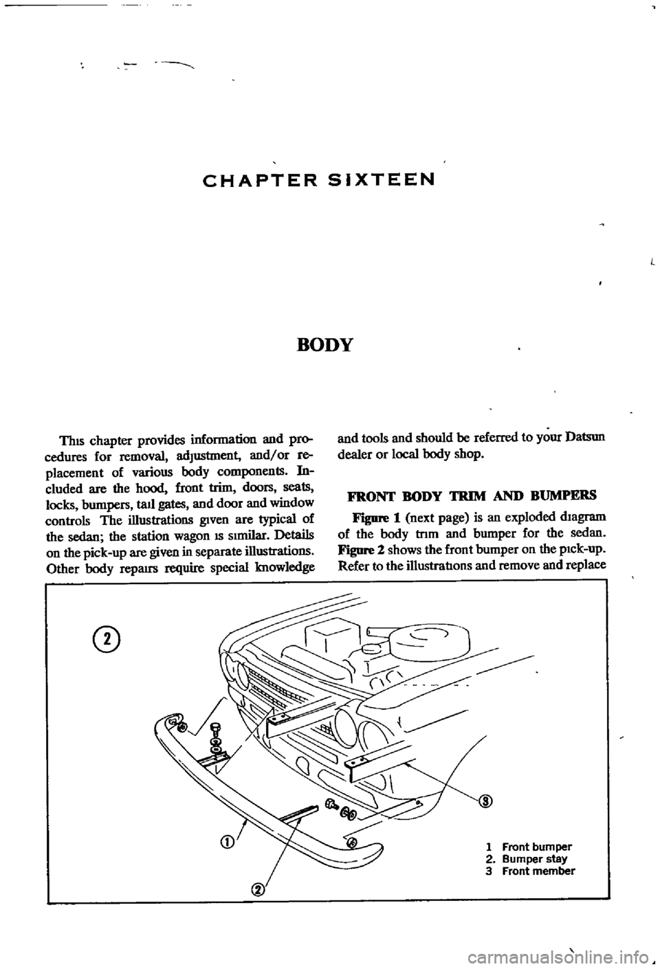
Figure
1
next
page
is
an
exploded
diagram
of
the
body
tnm
and
bumper
for
the
sedan
Figure
2
shows
the
front
bumper
on
the
pick
up
Refer
to
the
illustratIons
and
remove
and
replace
1
Front
bumper
2
Bumper
stay
3
Front
member
Page 235 of 252

228
CHAPTER
SIXTEEN
1
lock
knob
2
lock
installation
bolt
3
Bell
crank
installation
bolt
4
Door
lock
remote
control
assembly
5
Door
lock
assembly
6
OutsIde
handle
lever
7
InSide
lock
knob
IOstallatJon
bolt
CD
CD
D
00
TRUNK
LID
AND
BUMPER
Figure
10
page
230
shows
the
constructIon
details
of
the
sedan
trunk
lid
and
bumper
Figure
11
page
231
Illustrates
the
wagon
bumper
assembly
SEATS
Fre
12
page
232
IS
an
exploded
View
of
the
front
seat
and
mountIng
brackets
used
m
the
1
Door
panel
assembly
2
Door
Window
ventJlator
assembly
3
Door
Window
glass
4
Glass
run
5
Door
wmdow
weather
stnp
6
Door
outsIde
handle
7
Door
lock
key
cylinder
8
Door
lock
and
remote
control
assembly
9
Door
WIndow
regulator
10
InSIde
handle
11
Regulator
handle
12
Door
fimsh
13
Sealing
screen
14
Sealing
screen
15
Sealing
screen
16
Support
cushIon
@
FRONT
SEAT
FOR
PICK
UP
four
door
sedan
The
front
seats
and
mountmg
brackets
for
the
two
door
sedan
and
station
wagon
are
the
same
Figure
13
shows
the
seat
for
the
pIck
up
TAIL
GATE
Refer
to
Figure
14
page
233
for
details
of
the
statIon
wagon
tail
gate
Page 241 of 252
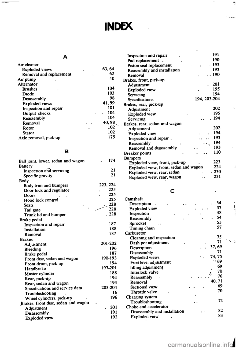
INDEX
A
Inspection
and
repair
191
Air
cleaner
Pad
replacement
190
Exploded
views
63
64
Piston
seal
replacement
193
Removal
and
replacement
62
Reassembly
and
installation
193
Removal
190
Air
pump
40
Brakes
front
pick
up
Alternator
Brushes
104
Adjustment
201
Diode
103
Exploded
View
195
Disassembly
98
ServiCing
194
SpecdicatIons
194
203
204
Exploded
Views
41
99
Brakes
rear
pick
up
Inspection
and
repair
101
Adjustment
202
Output
checks
104
Exploded
View
195
Reassembly
104
Servicing
194
Removal
40
98
Brakes
rear
sedan
and
wagon
Rotor
102
Adjustment
202
Stator
102
Exploded
view
194
Axle
removal
pick
up
175
Inspection
and
repair
193
Reassembly
194
B
Removal
and
disassembly
193
Breaker
points
110
Ball
JOint
lower
sedan
and
wagon
174
Bumpers
Battery
Exploded
view
front
pick
up
223
Inspecllon
aiii
I
servicing
21
Exploded
View
front
sedan
and
wagon
224
SpeCific
gravity
21
Exploded
view
rear
sedan
230
Body
Exploded
view
rear
wagon
231
Body
Irlm
and
bumpers
223
224
Door
lock
and
regulator
225
C
Doors
225
Hood
lock
control
225
Camshaft
Seats
228
DeSCription
34
Tail
gate
228
Exploded
view
37
Trunk
hd
and
bumper
228
Inspection
48
Brake
pedal
Reassembly
54
Inspection
and
repair
187
Sprocket
53
Installation
188
Tlmmg
chain
57
Removal
187
Carburetor
Brakes
Cleaning
and
inspection
75
Adjustment
201
202
Dash
pot
adjustment
71
Bleeding
196
DesCription
37
69
Brake
pedal
187
Disassembly
71
Front
diSC
sedan
and
wagon
190
193
Exploded
Views
74
75
Front
drum
pick
up
194
Fuel
level
adjustment
69
Handbrake
197
201
Idhng
adjustment
69
Master
cyhnder
188
Interlock
valve
70
Rear
pick
up
194
Reassembly
76
Rear
sedan
and
wagon
193
Removal
40
71
SpeCifications
and
service
data
203
204
Sectional
view
69
Troubleshooting
16
Throttle
valve
70
Wheel
cyhnders
pIck
up
196
Charging
system
Brakes
front
diSC
sedan
and
wagon
Troubleshooting
12
Adjustment
201
Choke
and
accelerator
Disassembly
191
Disassembly
and
installation
82
Exploded
view
192
Exploded
view
83
Page 245 of 252
l
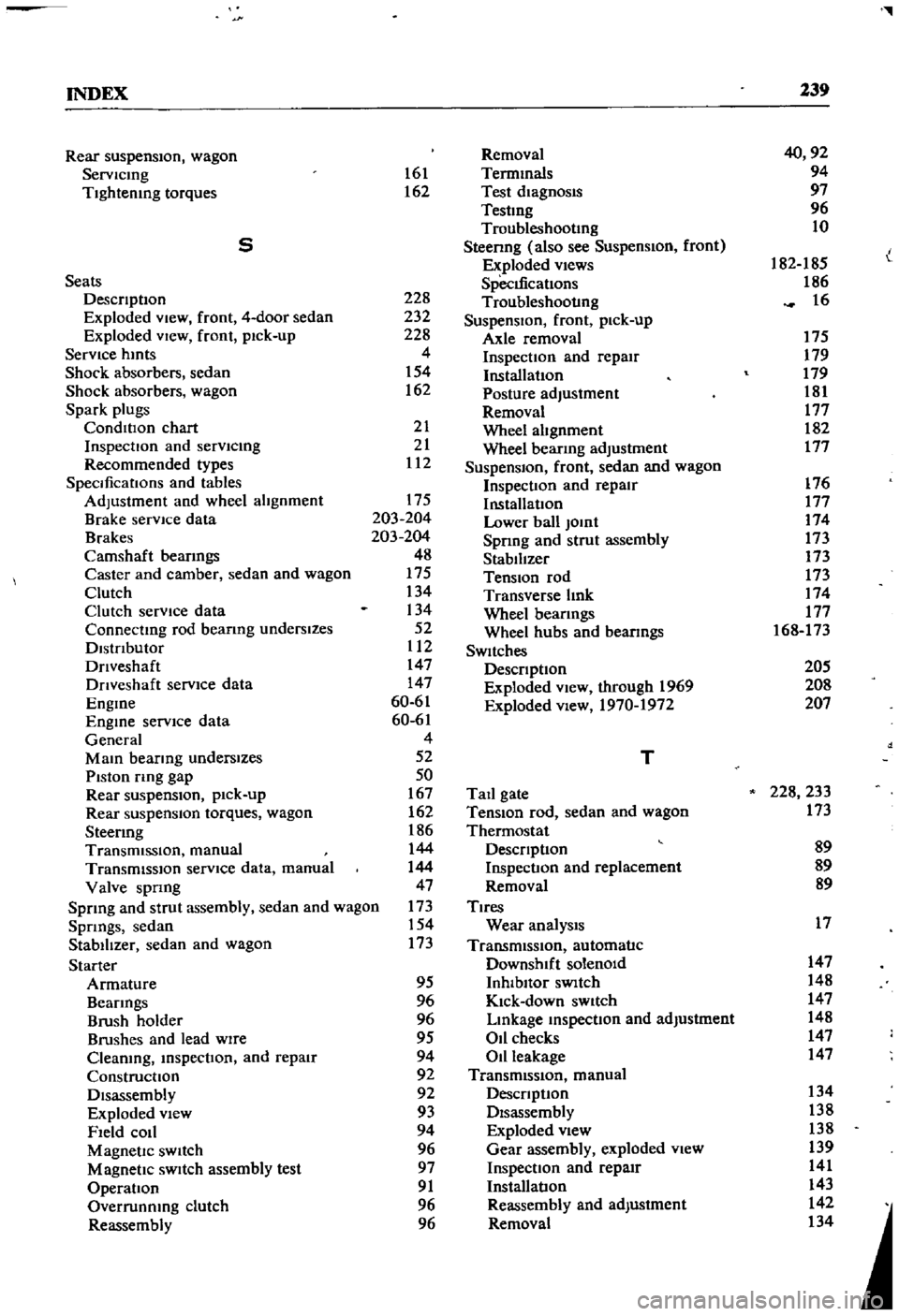
INDEX
239
Rear
suspensIOn
wagon
Removal
40
92
Servlcmg
161
Termmals
94
Tightening
torques
162
Test
diagnosIs
97
Testmg
96
Troubleshootmg
10
5
Steenng
also
see
Suspension
front
I
Exploded
views
182
185
L
Seats
SpecIfications
186
DescnptIon
228
Troubleshooting
16
Exploded
View
front
4
door
sedan
232
SuspensIOn
front
pick
up
Exploded
VIew
front
pick
up
228
Axle
removal
175
Service
hmts
4
Inspection
and
repair
179
Shock
absorbers
sedan
154
Installation
179
Shock
absorbers
wagon
162
Posture
adjustment
181
Spark
plugs
Removal
177
CondlllOn
chart
21
Wheel
abgnment
182
InspectIon
and
servlcmg
21
Wheel
bearmg
adjustment
177
Recommended
types
112
Suspension
front
sedan
and
wagon
SpecificatIOns
and
tables
Inspection
and
repair
176
Adjustment
and
wheel
alignment
175
InstallatIOn
177
Brake
service
data
203
204
Lower
ball
Jomt
174
Brakes
203
204
Spnng
and
strut
assembly
173
Camshaft
beanngs
48
Stabilizer
173
Caster
and
camber
sedan
and
wagon
175
TenSIOn
rod
173
Clutch
134
Transverse
bnk
174
Clutch
service
data
134
Wheel
beanngs
177
Connectmg
rod
beanng
underslzes
52
Wheel
hubs
and
bearmgs
168
173
Dlstnbutor
112
SWItches
Dnveshaft
147
DescnptIon
205
Dnveshaft
service
dala
147
Exploded
View
through
1969
208
Engme
60
61
Exploded
view
1970
1972
207
Engme
service
data
60
61
General
4
Mam
bearmg
underslzes
52
T
Piston
rmg
gap
50
Rear
suspenSIOn
pick
up
167
Tail
gate
228
233
Rear
suspensIOn
torques
wagon
162
TenSIOn
rod
sedan
and
wagon
173
Steermg
186
Thermostat
TransmiSSion
manual
144
DescnptIon
89
TransmiSSion
service
data
manual
144
Inspection
and
replacement
89
Valve
spnng
47
Removal
89
Sprmg
and
strut
assembly
sedan
and
wagon
173
Tires
Spnngs
sedan
154
Wear
analYSIS
17
Stabilizer
sedan
and
wagon
173
TransmiSSion
automatic
Starter
Downshift
solenOid
147
Armature
95
Inhlbllor
SWItch
148
Beanngs
96
Kick
down
SWitch
147
Brush
holder
96
Lmkage
mspectIon
and
adjustment
148
Brushes
and
lead
WIre
95
011
checks
147
Cleaning
mspectIon
and
repair
94
Oil
leakage
147
Construcllon
92
TransmiSSion
manual
Disassembly
92
DescnptIon
134
Exploded
View
93
Disassembly
138
Field
COIl
94
Exploded
view
138
Magnetic
SWItch
96
Gear
assembly
exploded
view
139
Magnetic
SWItch
assembly
test
97
Inspection
and
repair
141
Operation
91
Installation
143
Overrunnmg
clutch
96
Reassembly
and
adjustment
142
Reassembly
96
Removal
134