1968 DATSUN 510 key
[x] Cancel search: keyPage 40 of 252
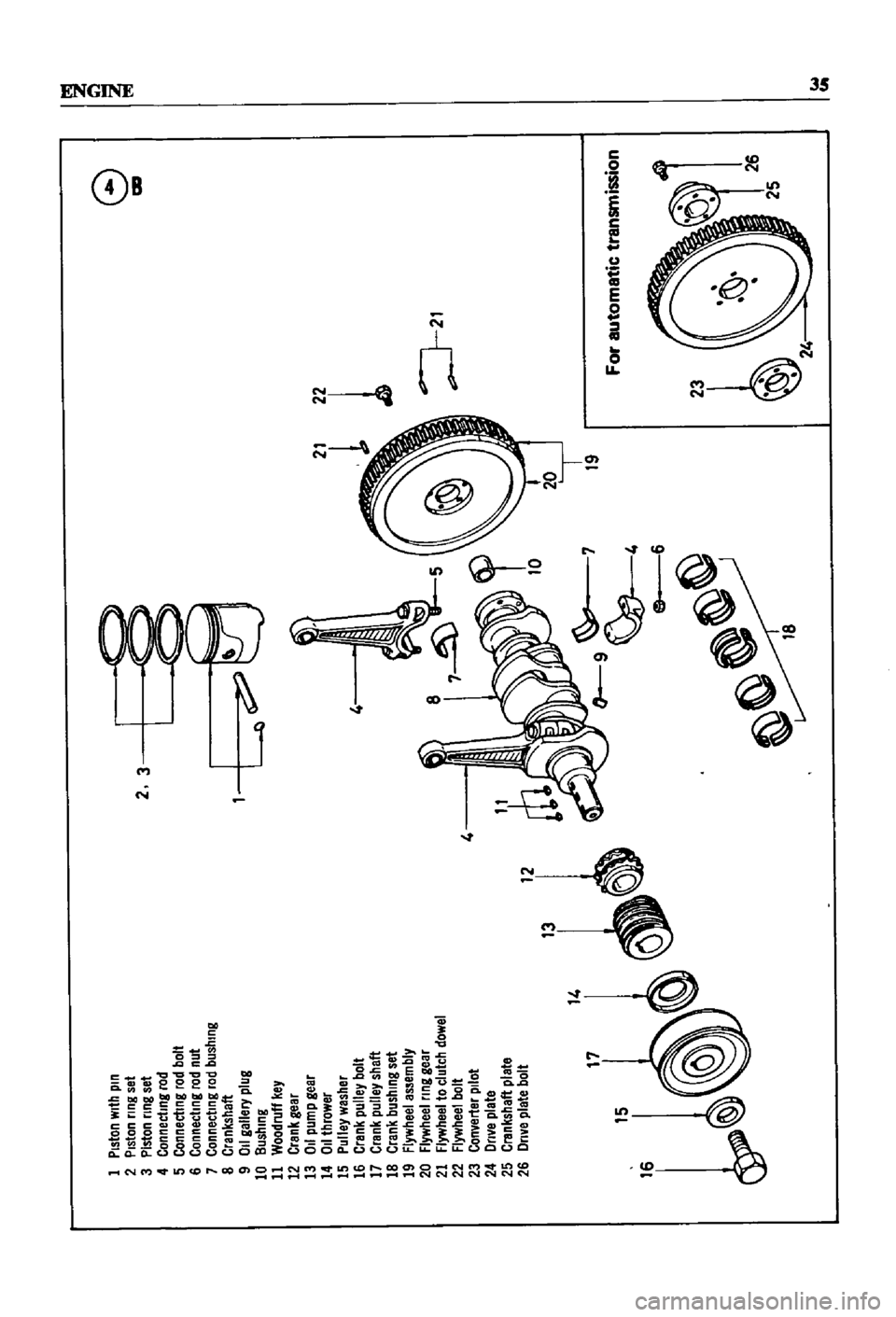
I
Piston
with
pin
2
Piston
nng
set
3
Piston
nng
set
4
Connecting
rod
5
Connecting
rod
bolt
6
Connecting
rod
nut
7
Connecting
rod
bushing
8
Crankshaft
9
011
gallery
plug
10
Bushing
11
Woodruff
key
12
Crank
gear
13
011
pump
gear
14
OJlthrower
15
Pulley
washer
16
Crank
pulley
bolt
17
Crank
pulley
shaft
18
Crank
bushing
set
19
Flywheel
assembly
20
Flywheel
nng
gear
21
Flywheel
to
clutch
dowel
22
Flywheel
bolt
4
23
Converter
pilot
24
Dnve
plate
25
Crankshaft
plate
26
Dnve
plate
bolt
13
I
14
17
15
2
3
l
L
4
8
9
6
19
1
J
21
2
24
8
ICD
I
For
automatic
transmission
W
lit
Page 48 of 252
ENGINE
43
@
0
00
o
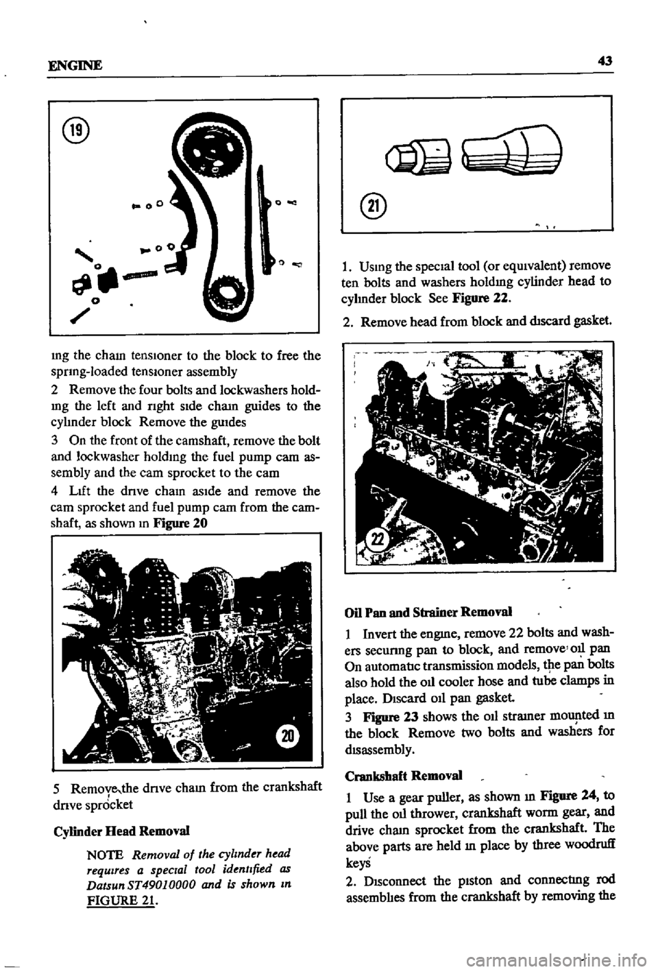
mg
the
cham
tenslOner
to
the
block
to
free
the
sprIng
loaded
tenslOner
assembly
2
Remove
the
four
bolts
and
lockwashers
hold
mg
the
left
and
rIght
sIde
cham
guides
to
the
cylmder
block
Remove
the
guIdes
3
On
the
front
of
the
camshaft
remove
the
bolt
and
lockwasher
holdIng
the
fuel
pump
cam
as
sembly
and
the
eam
sprocket
to
the
eam
4
LIft
the
drIve
chaIn
asIde
and
remove
the
earn
sprocket
and
fuel
pump
cam
from
the
cam
shaft
as
shown
In
Figure
20
5
Remove
the
dnve
cham
from
the
crankshaft
drIve
spr6cket
Cylinder
Head
Removal
NOTE
Removal
of
the
cylinder
head
requires
a
special
tool
identified
as
DatsunST49010000
and
is
shown
In
FIGURE
21
@
I
USIng
the
specIal
tool
or
eqUIvalent
remove
ten
bolts
and
washers
holdIng
cylinder
head
to
cyhnder
block
See
Figure
22
2
Remove
head
from
block
and
dtscard
gasket
Oil
Pan
and
Strainer
Removal
I
Invert
the
engme
remove
22
bolts
and
wash
ers
secunng
pan
to
block
and
remove
011
pan
On
automatIc
transmission
models
tpe
pan
bolts
also
hold
the
oIl
cooler
hose
and
tube
clamps
in
place
DISCard
011
pan
gasket
3
Figure
23
shows
the
oIl
stramer
mOlJ
lted
m
the
block
Remove
two
bolts
and
washers
for
dISassembly
Crankshaft
Removal
I
Use
a
gear
puller
as
shown
III
Figure
24
to
pull
the
oIl
thrower
crankshaft
worm
gear
and
drive
cham
sprocket
from
the
crankshaft
The
above
parts
are
held
In
place
by
three
woodruff
keyS
2
DISconnect
the
pIston
and
connectrng
rod
assemblIes
from
the
crankshaft
by
removing
the
Page 60 of 252

ENGINE
55
Cylinder
Block
Assembly
1
PositIon
all
crankshaft
parts
on
a
work
bench
ThIS
mcludes
the
crankshaft
main
beanngs
rear
011
seal
woodruff
keys
crankshaft
gear
011
pump
gear
011
thrower
bolts
and
bearing
caps
Figure
57
shows
the
arrangement
@
2
Insert
maIO
beanngs
mto
appropnate
cy1m
der
block
holders
NOTE
The
center
No
3
beanng
IS
the
only
flanged
type
of
thrust
bear
Ing
Bearings
No
2
and
No
4
are
Identical
No
1
and
No
5
Jaring
ap
pear
identical
but
No
1
as
an
011
hole
All
bearings
except
No
1
are
Interchangeable
as
to
upper
and
lower
half
3
LIghtly
lubncate
the
crankshaft
and
beanng
matmg
surfaces
then
mstall
beanngs
10
mam
beanng
caps
4
Install
the
crankshaft
5
Install
mam
beanng
caps
over
crankshaft
msert
mam
cap
bolts
and
tighten
hghtly
The
mam
beanng
caps
have
an
arrow
marked
on
each
one
These
must
pomt
to
the
front
of
the
engme
6
Gently
move
the
crankshaft
10
an
aXIal
drrec
don
toward
the
front
of
the
engme
to
venfy
that
the
mam
beanng
caps
are
properly
alIgned
and
seated
7
Use
a
torque
wrench
to
tighten
the
cap
bolts
to
the
hmlts
speCIfied
The
t1ghtenmg
operatIon
should
be
done
gradually
10
three
or
four
sep
arate
stages
starting
10
the
center
and
workmg
outward
to
each
end
8
Rotate
the
crankshaft
to
make
certain
it
isn
t
bmding
9
Use
a
feeler
gauge
to
check
the
end
play
at
the
center
No
3
beanng
Figure
58
10
Install
the
SIde
oll
seals
into
the
rear
mam
cap
and
cy1mder
block
as
shown
10
Figure
59
@
11
Install
the
rear
011
seal
WIth
Datsun
tool
ST49370000
or
equIvalent
12
Install
the
rear
end
plate
13
Install
the
flywheel
WIth
proper
bolts
and
lock
washers
and
torque
as
specified
Page 61 of 252
56
CHAPTER
SIX
NOTE
Lubncate
the
cylinder
walls
with
new
engine
oil
prior
to
insertIOn
of
pistOns
Make
certain
that
the
ring
gaps
are
not
In
line
wIth
one
another
Place
the
gaps
180
degrees
from
each
other
and
not
posltloned
either
front
to
back
or
dIrectly
in
line
with
the
piston
pIns
CAUTION
Use
extreme
care
when
Inserting
pzs
tons
so
as
to
avoId
crankshaft
damage
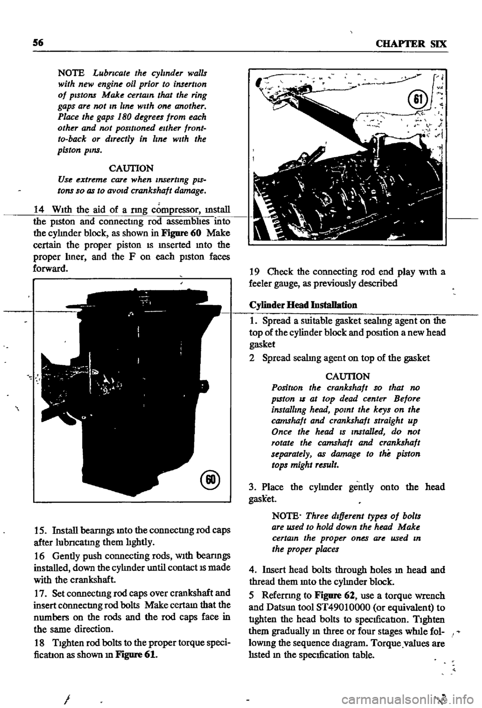
14
With
the
aid
of
a
nng
compressor
illStaIl
the
pISton
and
connectmg
rod
assembhes
into
the
cyhnder
block
as
shown
in
Figure
60
Make
certain
the
proper
piston
IS
mserted
mto
the
proper
hner
and
the
F
on
each
pISton
faces
forward
@
15
Install
beanngs
mto
the
connectIng
rod
caps
after
lubncatmg
them
hghtly
16
Gently
push
connecting
rods
With
beanngs
installed
down
the
cyhnder
until
contact
IS
made
with
the
crankshaft
17
Set
connectIng
rod
caps
over
crankshaft
and
insert
COnnectIng
rod
bolts
Make
certam
that
the
numbers
on
the
rods
and
the
rod
caps
face
in
the
same
direction
18
Tighten
rod
bolts
to
the
proper
torque
speci
ficatIon
as
shown
m
Figure
61
I
J
@v
N
i
19
Check
the
connecting
rod
end
play
With
a
feeler
gauge
as
previously
described
Cylinder
Head
Installation
1
Spread
a
suitable
gasket
seahng
agent
on
the
top
of
the
cylinder
block
and
position
a
new
head
gasket
2
Spread
seahng
agent
on
top
of
the
gasket
CAUTION
PositIon
the
crankshaft
so
that
no
pzston
IS
at
top
dead
center
Before
installing
head
point
the
keys
on
the
camshaft
and
crankshaft
straight
up
Once
the
head
zs
Installed
do
not
rotate
the
camshaft
and
crankshaft
separately
as
damage
to
the
piston
tops
might
result
3
Place
the
cyhnder
gently
onto
the
head
gask
et
NOTE
Three
dIfferent
types
of
bolts
are
used
to
hold
down
the
head
Make
certain
the
proper
ones
are
used
In
the
proper
places
4
Insert
head
bolts
through
holes
ill
head
and
thread
them
mto
the
cyhnder
block
5
Refemng
to
Figure
62
use
a
torque
wrench
and
Datsun
tool
ST49010000
or
equivalent
to
tIghten
the
head
bolts
to
specIficatIon
Tighten
them
gradually
m
three
or
four
stages
wlnle
fol
lOWIng
the
sequence
diagram
Torque
values
are
hsted
m
the
specIfication
table
Page 62 of 252
ENGINE
57
@
L
13
and
L
16
engme
000000
8
4
2
6
10
7
3
1
5
9
o
0
0
0
0
Front
Crankshaft
and
Timing
Chain
Assembly
1
Insert
a
woodruff
key
mto
the
crankshaft
key
way
and
slide
the
crankshaft
sprocket
mto
place
2
Insert
a
woodruff
key
m
the
Illiddle
crank
shaft
keyway
and
slide
the
dIstnbutor
dnve
gear
mto
place
3
FIt
the
oil
thrower
to
the
crankshaft
as
shown
m
Figure
63
NOTE
Make
certam
that
the
crank
shaft
and
camshaft
keys
are
polntlng
upwards
4
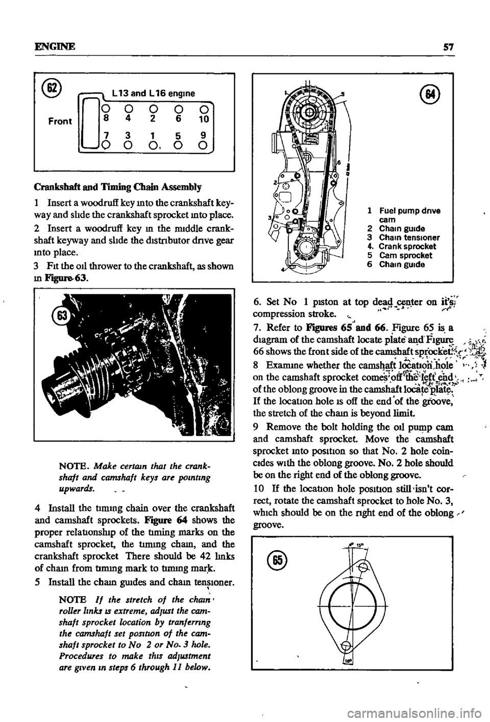
Install
the
tmung
chain
over
the
crankshaft
and
camshaft
sprockets
Figure
64
shows
the
proper
relatIonslnp
of
the
tIming
marks
on
the
camshaft
sprocket
the
tmung
cham
and
the
crankshaft
sprocket
There
should
be
42
hnks
of
cham
from
tmung
mark
to
tmung
mar
k
5
Install
the
cham
gwdes
and
cham
tensIoner
NOTE
If
the
stretch
of
the
cham
roller
links
IS
extreme
adJust
the
cam
shaft
sprocket
location
by
tranfernng
the
camshaft
set
pOSltlon
of
the
cam
shaft
sprocket
to
No
2
or
No
3
hole
Procedures
to
make
thIS
adJustment
are
gIVen
m
steps
6
through
II
below
@
1
Fuel
pump
drive
eam
2
Cham
gUide
3
Cham
tensloner
4
Crank
sprocket
5
Cam
sprocket
6
Cham
gUide
6
Set
N
1
pISton
at
top
de
8
n
r
on
f
compressIon
stroke
7
Refer
to
Figures
65
and
66
Figure
65
is
a
dIagram
of
the
camshaft
locate
piate
an
d
FI
1
66
shows
the
front
side
of
the
camshaft
sprOcKee5
r
11
r
If
8
Examme
whether
the
camshaft
locatIon
hole
y
on
the
camshaft
sprocket
com
ff
llii
sl
ff
end
foI
tri4o
of
the
oblong
groove
in
the
camshaft
locate
E
1litc
If
the
locatIon
hole
IS
off
the
end
of
the
groove
the
stretch
of
the
cham
is
beyond
limit
9
Remove
the
bolt
holding
the
oil
pwp
p
cam
and
camshaft
sprocket
Move
the
camshaft
sprocket
mto
posItIon
so
that
No
2
hole
coin
Cides
With
the
oblong
groove
No
2
hole
should
be
on
the
right
end
of
the
oblong
groove
10
If
the
locatIon
hole
posItIon
still
isn
t
cor
rect
rotate
the
camshaft
sprocket
to
hole
No
3
which
should
be
on
the
nght
end
of
the
oblong
groove
@
Page 63 of 252
58
CHAPTER
SIX
Notch
for
t1mmg
check
Camshaft
locatmg
hole
Timmg
mark
11
Should
none
of
the
above
adjustments
be
adequate
return
the
camshaft
sprocket
to
the
No
1
hole
and
replace
the
Oll
pump
cam
and
bolt
Under
these
conditIons
the
cham
must
be
replaced
Front
Cover
Crankshaft
Polley
And
Water
Pomp
InstaDation
1
Press
a
new
Oll
seal
into
the
front
cover
2
Apply
gasket
seahng
compound
to
both
sides
of
the
left
hand
and
nght
hand
front
cover
gaskets
Mount
the
gaskets
and
front
cover
to
the
block
With
bolts
and
lockwashers
Check
the
seal
of
the
head
gasket
at
the
top
of
the
front
cover
Make
certam
to
attach
bolts
at
that
locatlon
3
Insert
woodruff
key
into
crankshaft
and
slide
crankshaft
pulley
onto
crankshaft
4
Install
crankshaft
bolt
and
washer
then
torque
as
per
the
speclficatlon
table
5
Coat
water
pump
gasket
on
both
sides
With
gasket
compound
and
mount
the
water
pump
to
the
front
cover
as
shown
m
Figure
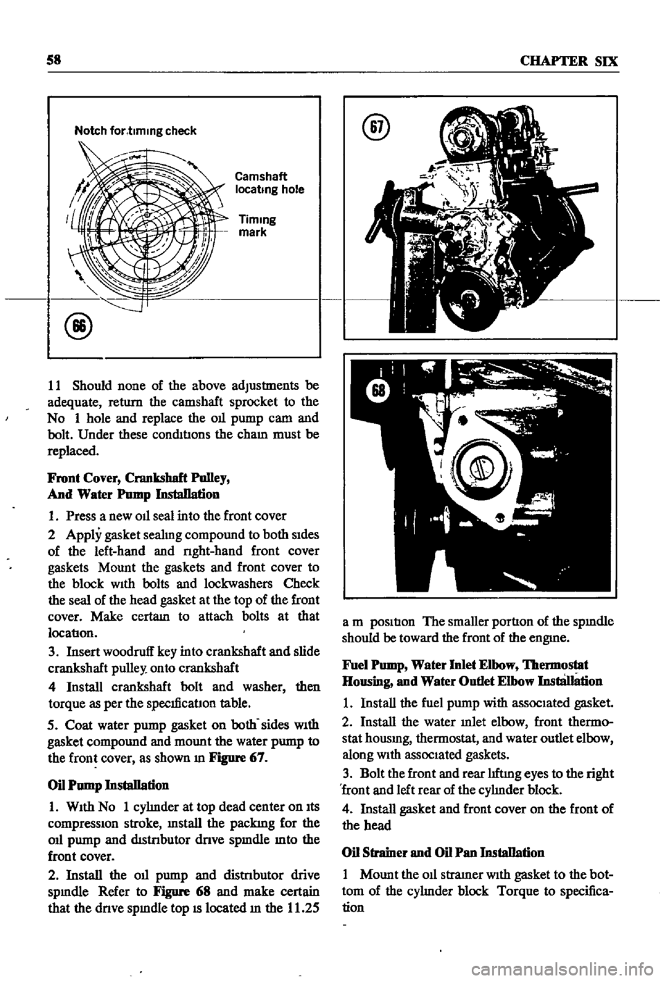
67
Oil
Pump
Installation
1
With
No
1
cyhnder
at
top
dead
center
on
Its
compressIOn
stroke
mstall
the
packing
for
the
Oll
pump
and
distnbutor
dnve
spmdle
mto
the
front
cover
2
Install
the
Oll
pump
and
distnbutor
drive
spmdle
Refer
to
Figure
68
and
make
certain
that
the
dnve
spmdle
top
IS
located
m
the
11
25
@
a
m
position
The
smaller
portion
of
the
spmdle
should
be
toward
the
front
of
the
engme
Fuel
Pomp
Water
Inlet
Elbow
lbermostat
Housing
and
Water
Outlet
Elbow
InstliJIation
1
Install
the
fuel
pump
with
associated
gasket
2
Install
the
water
mlet
elbow
front
thermo
stat
housmg
thermostat
and
water
outlet
elbow
along
With
associated
gaskets
3
Bolt
the
front
and
rear
hftmg
eyes
to
the
right
front
and
left
rear
of
the
cyhnder
block
4
Install
gasket
and
front
cover
on
the
front
of
the
head
Oil
Strainer
and
Oil
Pan
Installation
1
Mount
the
011
stramer
With
gasket
to
the
bot
tom
of
the
cyhnder
block
Torque
to
specifica
tion
Page 96 of 252
CHAPTER
NINE
ENGINE
ELECTRICAL
SYSTEM
The
electrIcal
system
has
undergone
slIght
yearly
changes
the
most
SignIficant
being
ill
the
distrIbutor
Some
models
have
a
smgle
contact
pomt
whIle
others
have
a
dual
pomt
system
De
talls
are
covered
m
the
dIstrIbutor
sectlon
The
electrIcal
system
IS
a
12
volt
negatIve
type
OPERATION
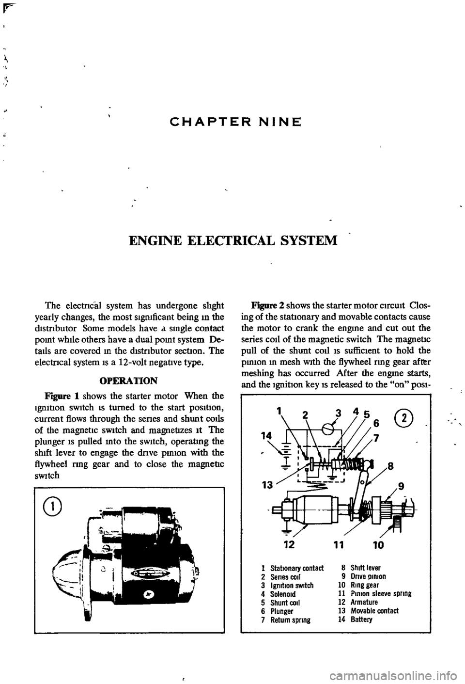
Figure
1
shows
the
starter
motor
When
the
Ignltlon
sWItch
IS
turned
to
the
start
pOSItIon
current
flows
through
the
senes
and
shunt
colis
of
the
magnetIc
SWitch
and
magnetizes
It
The
plunger
IS
pulled
mto
the
sWItch
operatlng
the
shIft
lever
to
engage
the
dnve
pmlon
with
the
flywheel
rmg
gear
and
to
close
the
magnetIc
SWitch
CD
Figure
2
shows
the
starter
motor
CIrcUIt
Clos
ing
of
the
statlonary
and
movable
contacts
cause
the
motor
to
crank
the
engme
and
cut
out
the
series
coIl
of
the
magnetic
switch
The
magnetic
pull
of
the
shunt
coll
IS
suffiCIent
to
hold
the
pmIOn
m
mesh
With
the
flywheel
nng
gear
after
meshing
has
occurred
After
the
engme
starts
and
the
Ignition
key
IS
released
to
the
on
POSI
1
CD
12
11
10
1
Stationary
contact
8
ShIlt
le
er
2
Sene
coli
9
Orne
pinion
3
IgmtlOn
SWitch
10
Ring
gear
4
Solenoid
11
Plmon
slee
e
spllng
5
Shunt
COil
12
Armature
6
Plunger
13
Movable
contact
7
Return
spllng
14
Battery
Page 104 of 252
ENGINE
ELECfRlCAL
SYSTEM
99
2
3
r
I
J
20
2
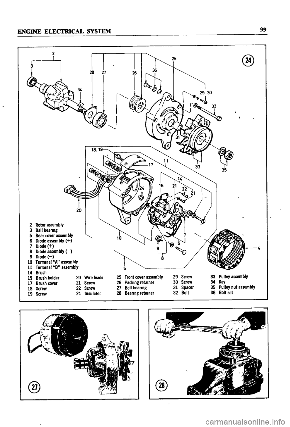
Rotor
aS5em
bly
3
Ball
beanng
5
Rear
cover
assembly
6
Diode
assembly
7
Diode
8
Diode
assembly
9
Diode
10
Terminal
A
assembly
11
Terminal
B
assembly
14
Brush
15
Brush
holder
17
Brush
co
er
18
Screw
19
Sa
ew
@
8
Front
cover
assembly
Packing
retainer
Ball
beanng
Beanng
retainer
29
Screw
30
Screw
31
Spacer
32
Bolt
33
Pulley
assembly
34
Key
35
Pulley
nut
assembly
36
Bolt
set
20
Wire
leads
21
Screw
22
Screw
24
Insulator
@
@