1968 DATSUN 510 steering
[x] Cancel search: steeringPage 5 of 252
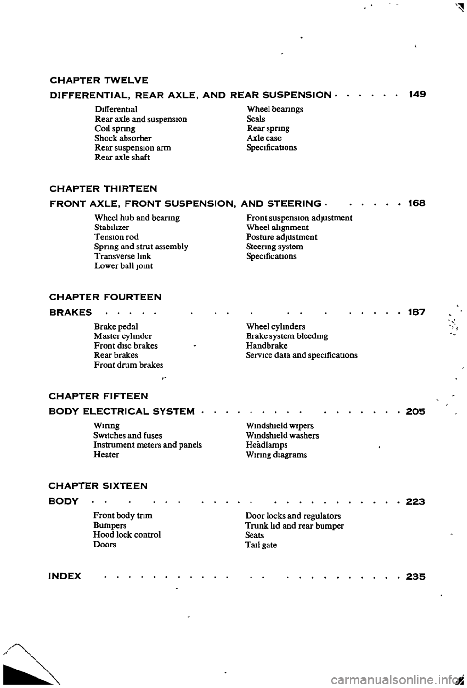
CHAPTER
TWELVE
DIFFERENTIAL
REAR
AXLE
AND
REAR
SUSPENSION
149
DIfferentIal
Rear
axle
and
suspension
Codspnng
Shock
absorber
Rear
suspensIOn
arm
Rear
axle
shaft
Wheel
beanngs
Seals
Rear
spnng
Axle
case
SpecificatIons
CHAPTER
THIRTEEN
FRONT
AXLE
FRONT
SUSPENSION
AND
STEERING
168
Wheel
hub
and
bearmg
StabilIzer
TenSion
rod
Spnng
and
strut
assembly
Transverse
lInk
Lower
ball
Jomt
Front
suspension
adjustment
Wheel
alignment
Posture
adJustment
Steenng
system
SpeCificatIons
CHAPTER
FOURTEEN
BRAKES
187
Brake
pedal
Master
cylInder
Front
diSC
brakes
Rear
brakes
Front
drum
brakes
Wheel
cylInders
Brake
system
bleedIng
Handbrake
Service
data
and
speCificatIons
CHAPTER
FIFTEEN
BODY
ELECTRICAL
SYSTEM
Wmng
SWitches
and
fuses
Instrument
meters
and
panels
Heater
205
Wmdshleld
wipers
Wmdslueld
washers
Headlamps
WIrIng
diagrams
CHAPTER
SIXTEEN
BODY
223
Front
body
trIm
Bumpers
Hood
lock
control
Doors
Door
locks
and
regulators
Trunk
lId
and
rear
bumper
Seats
Tad
gate
INDEX
235
I
Page 10 of 252
GENERAL
INFORMATION
5
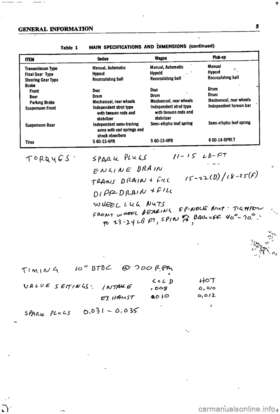
Table
1
MAIN
SPECIFICATIONS
AND
DIMENSIONS
continued
Suspension
Rear
Sedan
Wagon
Pick
up
Manual
Automatic
Manual
Automatic
Manual
HypoJd
Hypoid
Hypold
ReCIrculating
ball
ReCIrculating
ball
ReCirculating
ball
DIsc
DIsc
Drum
Drum
Drum
Drum
Mechanical
rear
wheels
Mechanical
rear
wheels
Mechanical
rear
wheels
Independent
strut
type
Independent
strut
type
Independent
torsion
bar
with
tension
rods
and
with
tension
rods
and
stabilizer
stabilIZer
Independent
semi
trailing
Semi
elliptiC
leaf
spring
Semi
elliptic
leaf
spnng
arms
wrtII
coli
springs
and
shock
absorbers
5
6O
13
4PR
5
6O
13
4PR
600
14
6PRLT
ITEM
Transmission
Type
Final
Gear
Type
Steering
Gear
Type
Brake
Front
Rear
Parking
Brake
Suspension
Front
Tires
6
2
Q
1
C
S
PA
l
PlLlU
EN
4
1
AJ
E
Dt7
A
1
1
1
2
A
ru
r
f
f
A
I
III
r
c
o
I
pP
D
LA
I
tV
r
IL
c
W
L
L
l
G
ftiv
TJ
dE
IJ
S
prlc
I
u
F
l
e
p
f
vi
Ii
ftl
1
3
l
1t
J
p7
5
PrlV
B4dc
u
11
1
S
t
f
PT
f
L
UJ
ff
zr
F
T
ff
lfo
1oo
4
t
M
0
IY
AJ
to
BTOL
@
OD
2
lP
S
PAtl
pI
c
5
IN
G
ex
Sf
0103
I
D
0
3
O
j
oo
0
0
0
to
l
c
o
0
0
2
JP
t
UE
SEIT
A
C
1
J
Page 21 of 252
16
CHAPTER
TIlREE
sary
Also
check
all
parts
for
mlSaltgnment
and
uneven
wear
TRANSMISSION
1
Difficult
to
mesh
gears
Make
certam
the
clutch
pressure
plate
and
re
lease
beanng
are
m
good
condItion
The
trouble
can
be
caused
by
worn
gears
shaft
and
or
bear
mgs
DISassemble
and
repaIr
as
requIred
Also
can
be
caused
by
msufficlent
operatmg
stroke
due
to
worn
or
loose
sltdmg
parts
or
a
defective
synchronIZer
DIsassemble
carefully
InSpect
and
replace
as
requIred
2
Gears
slip
out
of
mesh
Generally
thIS
trouble
occurs
when
the
mterlock
plunger
check
ball
and
or
spnng
IS
weakened
or
worn
The
trouble
can
also
be
caused
by
worn
fork
rod
ball
groove
damaged
bearings
or
dam
aged
gears
DIsassemble
carefully
mspect
and
replace
as
required
3
NOIse
If
nOISes
are
heard
wIth
the
engme
idlmg
and
the
clutch
disengaged
the
nOIse
IS
probably
conung
from
the
transmISSIOn
Several
Items
can
cause
nOISes
either
smgly
or
m
combmatIon
Check
the
qualIty
and
quantity
of
lubrIcant
in
the
trans
mISSIon
Replace
or
replenISh
as
necessary
Worn
bearIngs
wIll
usually
produce
a
lugh
humming
at
hIgh
speed
and
a
cycltc
knockIng
sound
at
low
speed
Worn
or
damaged
splInes
and
bushmgs
will
also
cause
nOIse
BRAKES
1
Brake
pedal
goes
to
floor
There
are
numerous
causes
for
thIS
includIng
excessIvely
worn
Itnmgs
aIr
in
the
hydraultc
sys
tem
leaky
brake
lmes
leaky
wheel
cylmders
or
leaky
or
worn
master
cylmder
Check
for
leaks
and
thIn
brake
linmgs
Bleed
and
adjust
the
brakes
If
thIS
doesn
t
cure
the
trouble
rebwld
wheel
cylmders
a
nd
or
master
cylmder
2
Spongy
pedal
Normally
caused
by
aIr
m
the
system
blee
d
and
adjust
the
brakes
3
Brakes
pull
Check
brake
adjustment
Also
check
for
contam
inated
brake
Itmngs
from
leaks
leaky
wheel
cyltnders
loose
caltpers
frozen
or
seIZed
pIstons
and
restrIcted
brake
lmes
or
hoses
In
addItion
check
front
end
alignment
and
suspensIOn
dam
age
such
as
broken
front
or
rear
sprmgs
shocks
etc
Check
condItIon
of
tIres
4
Brakes
squeal
or
chatter
Check
brake
lmmg
thickness
and
brake
drum
roundness
Ensure
that
the
shoes
have
cham
ferred
ends
and
are
not
loose
Inspect
the
condI
tion
of
the
rotors
on
the
front
wheel
dISC
brakes
to
make
certain
they
are
not
scored
or
damaged
Clean
away
all
dIrt
on
shoes
pads
rotors
or
drums
5
Draggmg
brakes
Check
brake
adjustment
includmg
handbrake
Check
for
broken
or
weak
shoe
return
springs
swollen
rubber
parts
due
to
unproper
brake
flUId
or
other
contammatIon
Clean
or
replace
de
fectIve
parts
6
Hard
pedal
Check
brake
linmgs
for
contammation
Also
check
for
restrIcted
brake
lines
and
hoses
7
High
speed
fade
Check
for
dIstorted
or
out
of
round
drums
and
contamInated
brake
lmmgs
Make
certam
the
recommended
brake
flUId
IS
used
Dram
entIre
system
and
refill
If
In
doubt
8
Pulsatmg
pedal
Check
for
dIStorted
or
out
of
round
drums
or
rotors
Check
for
excessIVe
brake
dISC
run
out
STEERING
AND
SUSPENSION
NOTE
Unusual
steermg
pullmg
or
wandermg
IS
usually
caused
by
bent
or
otherwise
mIsaligned
suspenszon
parts
Because
of
the
speCialized
equIp
ment
reqUired
to
evaluate
and
correct
these
faults
It
IS
recommended
t
tat
servIce
to
the
steermg
and
suspension
system
be
referred
to
your
Datsun
dealer
oca
quallfied
specrallst
m
thiS
field
1
VibratIOn
felt
m
steermg
wheel
VIbratIon
can
be
caused
by
several
thmgs
includ
ing
lll1proper
aIr
pressure
m
tIres
uneven
wear
Page 22 of 252

TROUBLESHOOTING
17
of
tIre
loose
wheels
unproper
adjustment
or
wear
of
front
wheel
bearIngs
faulty
wheel
align
ment
or
wear
of
transverse
lInk
and
tension
rod
bushings
Inspect
all
parts
carefully
for
wear
or
damage
Replace
or
replUI
parts
as
required
2
Shock
transmltled
through
steering
wheel
This
is
usually
most
noticeable
when
traveling
over
bad
roads
at
relatively
high
speeds
Causes
Include
damage
to
the
idler
ann
insuffiCient
tIghtening
of
steenng
gear
box
wear
of
the
steer
Ing
linkage
and
wear
of
the
suspension
ball
joint
Inspect
all
parts
for
wear
or
damage
Refer
to
Chapter
ThIrteen
for
service
or
repair
you
can
perform
and
for
procedures
which
should
be
referred
to
your
deal
r
3
Shlmmymg
This
is
usually
most
noticeable
when
a
specIfic
speed
IS
attained
and
will
normally
repeat
at
that
speed
Causes
are
generally
unbalanced
wheels
unproper
adjustment
of
steenng
gear
insuffi
cient
backlash
malfunction
of
the
shock
ab
sorbers
or
loose
bolts
for
the
strut
mountIng
Reparr
or
replace
defective
parts
as
required
Refer
to
Chapter
Thirteen
4
Wandermg
of
car
m
one
dlrectlOnl
This
problem
can
be
caused
by
improper
air
pressure
loose
wheel
nuts
difference
in
tire
tread
wear
from
left
to
right
side
Incorrect
adjustment
of
wheel
bearings
defectIve
wheel
beanngs
collapsing
or
twistIng
of
front
spnng
or
Incorrect
wheel
alignment
Also
binding
of
the
brake
shoes
worn
bushings
in
the
transverse
link
or
the
tension
rod
and
deformation
of
s
enng
lInkage
and
suspension
link
can
cause
wander
Carefully
iuspect
all
parts
for
looseness
and
wear
and
re
place
or
repaIr
as
required
In
some
c
ases
a
de
fective
rear
suspension
may
also
cause
the
vehicle
to
wander
5
InstabIlity
Instability
can
be
caused
by
unproper
tIre
pres
sures
worn
bushings
in
the
transverse
link
and
tension
rod
mcorrect
wheel
alignment
worn
steenng
linkage
Incorrect
adjustment
of
steer
ing
gear
and
unbalanced
wheels
Inspect
all
parts
carefully
for
wear
and
damage
Adjust
repair
or
replace
as
required
6
Heavy
feelmg
m
steering
This
can
be
caused
by
improper
tIre
pressures
insuffiCient
or
contamInated
lubncant
in
gear
box
damage
or
insuffiCient
grease
In
suspeuslon
ball
Joint
damaged
or
badly
adjusted
wheel
bearIngs
worn
or
damaged
steermg
gear
dam
age
of
upper
strut
bearing
and
mterference
of
steenng
column
With
turn
signal
SWitch
Inspect
all
parts
carefully
for
wear
and
damage
Adjust
repair
or
replace
as
required
7
ExceSSIve
play
m
steermg
wheel
This
is
usually
caused
by
Incorrect
adjustment
of
the
steenng
gear
worn
bushings
in
the
steering
linkage
or
Idler
arm
mcorrect
adjustment
of
the
front
wheel
bearings
worn
bushIngs
in
the
trans
verse
lInk
and
tension
rod
Carefully
inspect
all
parts
for
wear
or
damage
Adjust
repair
or
re
place
as
reqUIred
TIRE
WEAR
ANALYSIS
Abnormal
tIre
wear
should
always
be
ana
lyzed
to
deternune
the
cause
The
most
common
are
Incorrect
tIre
pressure
improper
dnving
overloading
and
Incorrect
wheel
ahgDment
Figures
2A
through
2F
identify
wear
patterns
and
mdicate
likely
causes
Of
I
1
l
D
1
Undennflatlon
Worn
more
on
Sides
than
In
center
Page 173 of 252
CHAPTER
THIRTEEN
FRONT
AXLE
FRONT
SUSPENSION
AND
STEERING
A
strut
type
front
suspension
IS
used
on
sedans
and
wagons
The
shock
absorber
and
the
spmdle
are
a
smgle
urnt
which
is
supported
by
a
coIl
spnng
on
the
upper
end
and
by
the
trans
verse
lInk
on
the
lower
end
Figures
1
2
nnd
3
are
exploded
dIagrams
of
the
axle
and
suspen
SIon
system
used
FIgure
1
Illustrates
the
axle
Figure
2
shows
the
sedan
suspenSlOn
and
FIgure
3
covers
the
wagon
Front
suspensIOn
on
the
pIck
up
IS
a
double
wIShbone
mdependent
deSign
which
uses
torsIon
bars
Figure
4
IS
a
cross
sectional
view
WHEEL
HUB
AND
WHEEL
BEARING
SEDAN
AND
WAGON
Wheel
Hub
nnd
Wheel
Bearing
Removal
Sednn
aud
Wagon
1
Jack
up
the
front
of
the
vehicle
and
support
It
on
stands
2
Remove
the
wheels
3
Detach
brake
hose
connector
at
frame
4
Remove
calIper
fiXlng
bolts
and
then
cahper
See
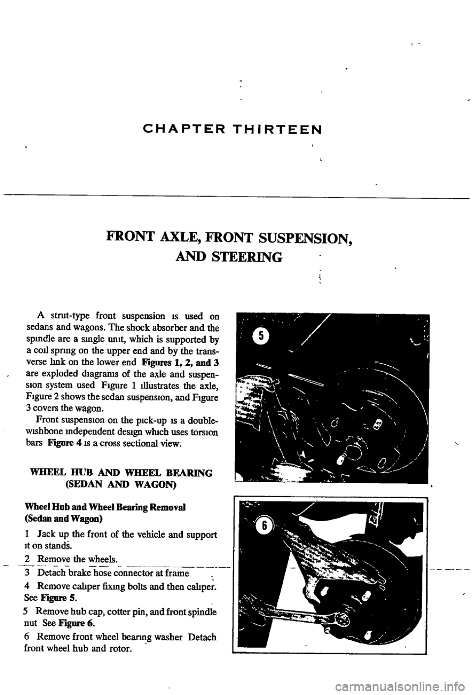
Figure
5
5
Remove
hub
cap
cotter
pin
and
front
spindle
nut
See
Figure
6
6
Remove
front
wheel
bearmg
washer
Detach
front
wheel
hub
and
rotor
ft
V
0
y
F
I
I
J
j
0
l
l
4
f
Page 178 of 252
FRONT
AXLE
FRONT
SUSPENSION
AND
STEERING
173
Spindle
Nut
21
7
to
253ft
Ib
30to35kg
m
528
to
716
ft
Ib
7
3
to
9
9
kg
m
282
to
38
3
fl
Ib
3
9to
5
3
kg
m
195
to
26
8
fl
b
2
7to3
7
kg
m
Caliper
FIXing
Bolts
Rotor
Flxmg
Bolls
Back
Plate
fiXIng
Boft
STABILIZER
SEDAN
AND
WAGON
SfBbilizer
Removal
Sednn
and
Wagon
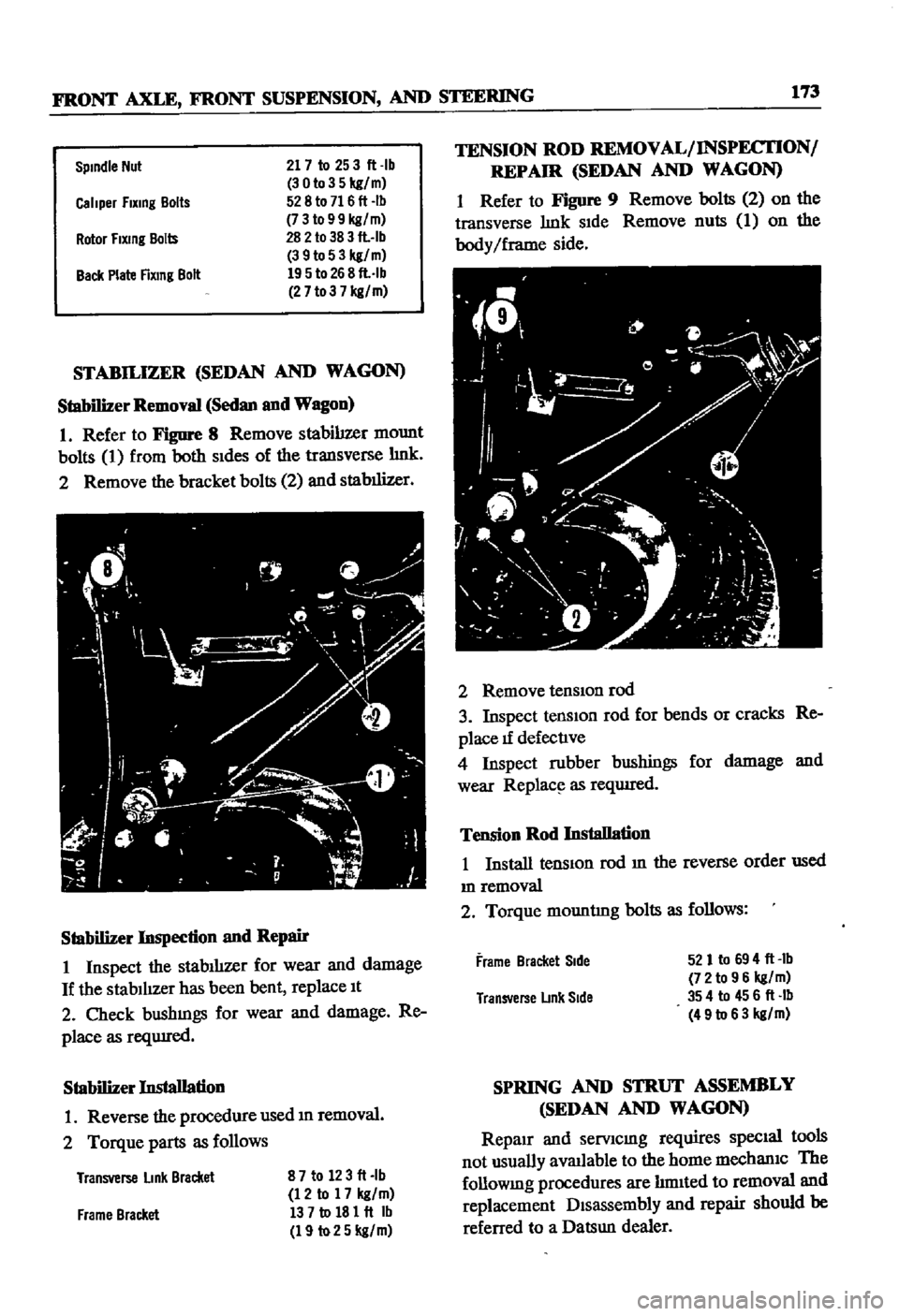
1
Refer
to
Figure
8
Remove
stabilizer
mount
bolts
1
from
both
Sides
of
the
transverse
hnk
2
Remove
the
bracket
bolts
2
and
stabilizer
Stabilizer
Inspection
nnd
Repair
1
Inspect
the
stablhzer
for
wear
and
damage
If
the
stabilIzer
has
been
bent
replace
It
2
Check
bushmgs
for
wear
and
damage
Re
place
as
reqUIred
Stabilizer
Installation
1
Reverse
the
procedure
used
m
removal
2
Torque
parts
as
follows
Transverse
link
Bracket
87to
123ft
lb
12
to
17
kg
m
137tol81ft
Ib
19
to25
kg
m
Frame
Bracket
TENSION
ROD
REMOVAL
INSPECTION
REPAIR
SEDAN
AND
WAGON
1
Refer
to
Figure
9
Remove
bolts
2
on
the
transverse
hnk
SIde
Remove
nuts
1
on
the
body
Iframe
side
2
Remove
tensIOn
rod
3
Inspect
tensIOn
rod
for
bends
or
cracks
Re
place
1f
defective
4
Inspect
rubber
bushings
for
damage
and
wear
Replac
l
as
reqwred
Tension
Rod
Installation
1
Install
tension
rod
m
the
reverse
order
used
m
removal
2
Torque
mountIng
bolts
as
follows
Frame
Bracket
Side
521
to
694
ft
Ib
72
to
96
kg
m
354
to
456ft
Ib
49
to
63
kg
m
Transverse
LInk
Side
SPRING
AND
STRUT
ASSEMBLY
SEDAN
AND
WAGON
Repair
and
serVicmg
requires
SpecIal
tools
not
usually
avaJlable
to
the
home
mechaniC
The
followmg
procedures
are
hmIted
to
removal
and
replacement
Disassembly
and
repair
should
be
referred
to
a
Datsun
dealer
Page 180 of 252
FRONT
AXLE
FRONT
SUSPENSION
AND
STEERING
175
2
Remove
bolt
cormectIng
strut
and
knuckle
arm
3
Remove
cotter
pm
and
lower
ball
Joint
4
Separate
lower
ball
Jomt
from
knuckle
arm
5
Remove
bolts
for
lower
ball
Jomt
Separate
transverse
lmk
from
lower
ball
Joint
6
Inspect
ball
Jomt
and
dust
cover
for
wear
or
damage
Replace
as
requIred
If
end
play
m
the
aXial
dIrectIon
of
the
ball
Jomt
exceeds
00012
to
0
0136
m
0
03
to
0
6mm
replace
It
7
Install
ball
Jomt
m
the
reverse
of
removal
Grease
It
through
the
grease
mpple
Take
care
to
fill
the
caVity
slowly
so
that
grease
does
not
come
out
from
the
clamp
portIon
8
Torque
bolts
as
follows
Lower
Ball
JOint
to
Transverse
Link
Ball
Stud
Nut
13
7
to
18
1
fl
Ib
19
to
25
kgfm
398
to
55
0
fl
Ib
55
to
76
kgfm
43
4
to
57
8
flAb
60
to
80
kgfm
35
4
to
45
6
flAb
49
to
63
kgfm
87
to
12
3
fl
lb
12
to
17
kgfm
Knuckle
Ann
to
Strut
TenSion
Rod
to
Transverse
Link
Stabilizer
to
Transverse
Link
FRONT
SUSPENSION
ADJUSTMENT
AND
WHEEL
ALIGNMENT
SEDAN
AND
WAGON
Due
to
the
speclahzed
eqUIpment
required
front
suspensIOn
adJustment
and
wheel
ahgn
ment
should
be
referred
to
a
Datsun
dealer
or
front
end
speciahst
The
followmg
specmcations
apply
to
the
sedan
and
wagon
Sedan
Wagon
Caster
1
40
20
00
Camber
1
00
20
10
King
Pin
Incllnallon
8000
7050
Toe
In
0236
to
0
354
In
0118
to
0
236
In
6
to
9mm
3
to
6mm
Steenng
Angle
In
38
to
390
38
to
390
Steenng
Angle
Out
22030
to
330
30
220
30
to
330
30
Front
Axle
Removal
Pick
up
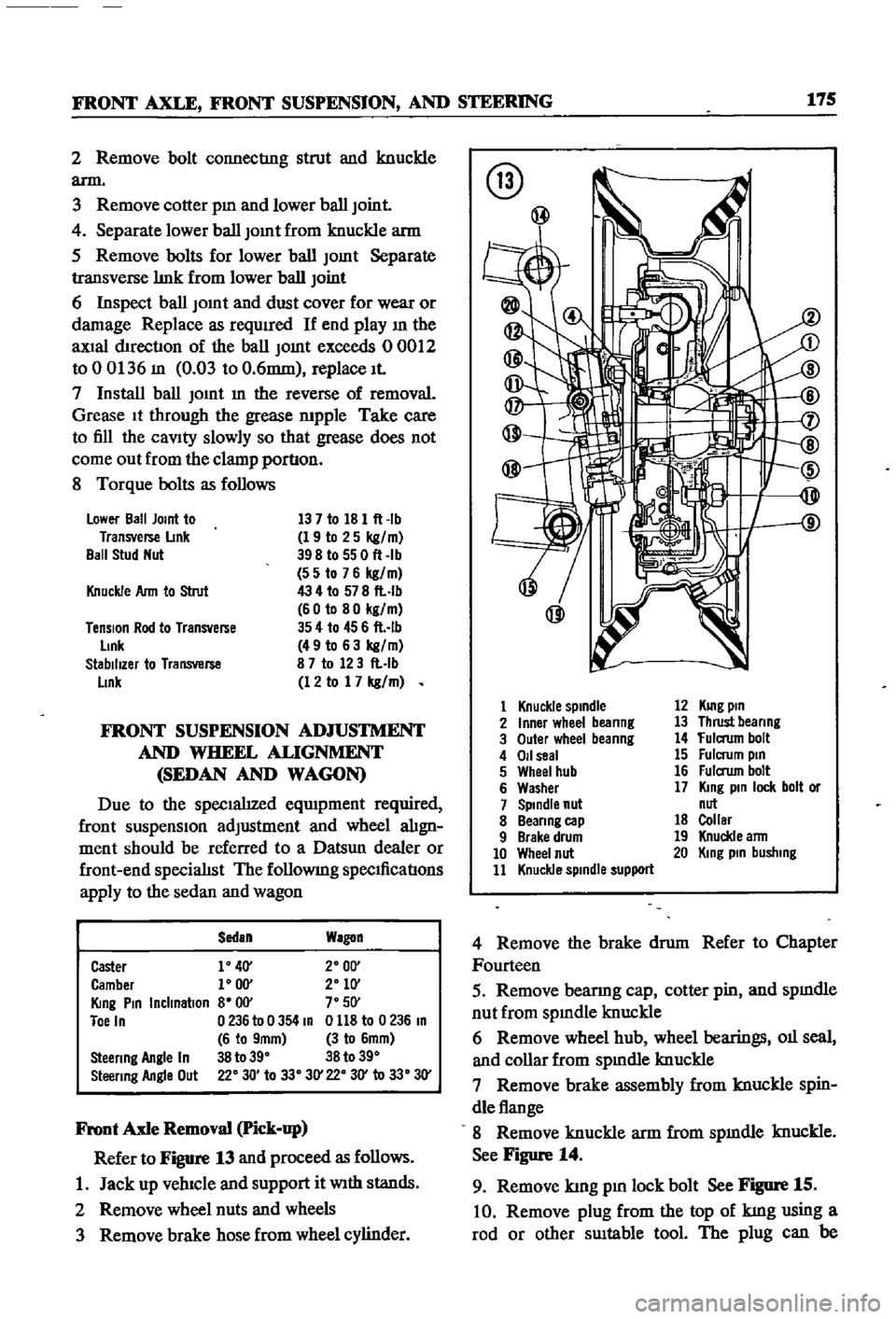
Refer
to
Figure
13
and
proceed
as
follows
1
Jack
up
vehIcle
and
support
it
With
stands
2
Remove
wheel
nuts
and
wheels
3
Remove
brake
hose
from
wheel
cylinder
@
@
1
Knuckle
spindle
2
Inner
wheel
beanng
3
Outer
wheel
beanng
4
011
seal
5
Wheel
hub
6
Washer
7
Spindle
nut
8
Beanng
cap
9
Brake
drum
10
Wheel
nut
11
Knuckle
spindle
support
12
KUlg
pin
13
Thrust
beanng
14
fulaum
bolt
15
Fulcrum
pin
16
Fulaum
bolt
17
King
pin
lock
bolt
or
nut
18
Collar
19
Knuckle
ann
20
King
pin
busllIng
4
Remove
the
brake
drum
Refer
to
Chapter
Fourteen
5
Remove
bearmg
cap
cotter
pin
and
spmdle
nut
from
spmdle
knuckle
6
Remove
wheel
hub
wheel
bearings
011
seal
and
collar
from
spmdle
knuckle
7
Remove
brake
assembly
from
knuckle
spin
dle
flange
8
Remove
knuckle
arm
from
spmdle
knuckle
See
Figure
14
9
Remove
kmg
pm
lock
bolt
See
Figure
15
10
Remove
plug
from
the
top
of
kmg
using
a
rod
or
other
SUItable
tool
The
plug
can
be
Page 182 of 252
FRONT
AXLE
FRONT
SUSPENSION
AND
STEERING
177
5
Check
front
hub
for
cracks
and
damage
Re
place
1f
defectIve
6
Check
thrust
bearmg
for
wear
damage
rust
and
ease
of
rotatIon
Replace
1f
defectIve
Front
Suspension
Installation
1
Remstallation
is
the
reverse
of
removal
2
Apply
hght
coatIng
of
multI
purpose
grease
to
all
shdmg
parts
3
Install
bushmg
carefully
so
that
grease
groove
IS
on
the
upper
Side
and
the
bushmg
Joint
is
faced
rearward
Remove
grease
mpple
and
dn11
grease
hole
through
bushmg
through
hole
With
an
0
1181
m
3mm
dn11
Remove
metal
shaVlDgs
and
burrs
Ream
the
mner
d1ameter
of
the
bushing
to
07878
to
0
7888
m
20
010
to
20035mm
4
Install
thrust
bearmg
so
that
the
covered
face
Side
is
upward
5
Push
up
the
bottom
of
the
spmdle
hghtly
Measure
clearance
and
select
a
spmdle
shim
to
prOVide
the
followmg
clearance
standard
Clearance
0
001
In
004mm
ShIms
are
available
m
vanous
thicknesses
6
FIt
kmg
pm
and
make
certam
It
operates
smoothly
7
Apply
sealer
to
new
plug
and
install
8
Install
bearmg
outer
race
Fill
wheel
hub
and
hub
cap
With
multI
purpose
grease
Fill
space
between
wheel
bearing
rollers
and
grease
seal
hp
pocket
With
multI
purpose
grease
Make
cer
tam
wheel
beanngs
are
coated
completely
9
Apply
multI
purpose
grease
to
spmdle
shaft
wheel
bearmg
washer
and
to
the
wheel
bearmg
lock
nut
10
Make
certam
that
no
dIrt
or
foreign
matenal
IS
permitted
m
contact
with
parts
or
grease
dunng
assembly
Wheel
Bearing
Adjustment
1
Install
spindle
nut
and
torque
to
23
1
to
24
6
ft
lb
3
2
to
3
4
kg
m
2
Turn
wheel
hub
a
few
tImes
m
both
the
clock
Wise
and
counterclockwISe
directIon
Recheck
the
spmdle
nut
tighmess
3
Back
off
spmdle
nut
from
40
to
70
degrees
until
hole
m
spmdle
and
nut
COinCIde
Insert
cotter
pm
and
bend
over
around
nut
4
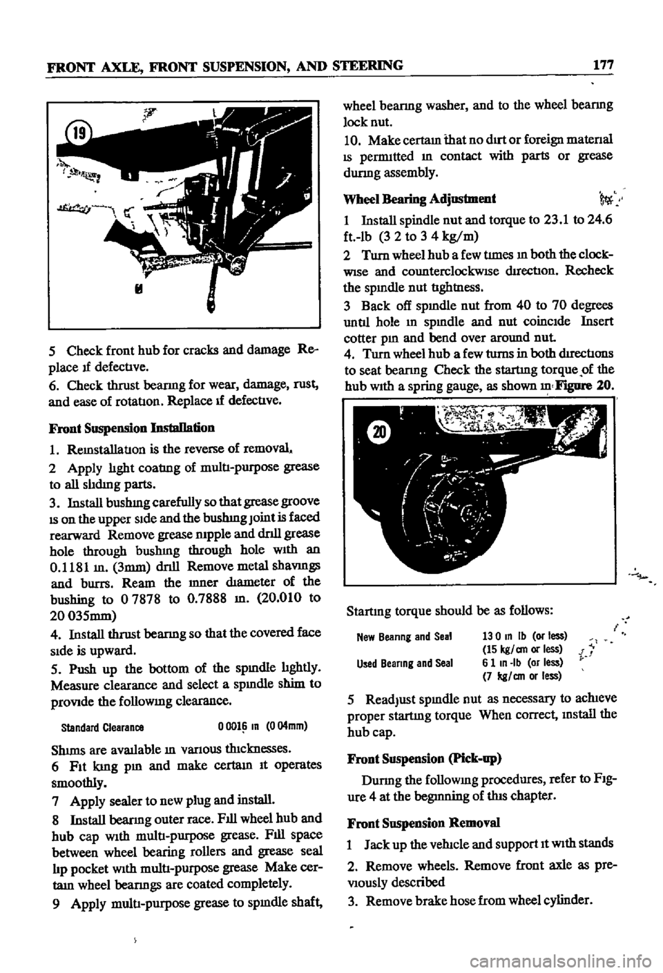
Turn
wheel
hub
a
few
turns
in
both
d1rectIons
to
seat
bearmg
Check
the
startmg
torque
of
the
hub
With
a
spring
gauge
as
shown
Figure
20
Startmg
torque
should
be
as
follows
New
Beanng
and
Seal
130
In
Ib
or
less
15
kgl
an
or
less
i
Used
Beanng
and
Seal
6
1
In
Ib
or
less
7
kgl
an
or
less
5
ReadJust
spmdle
nut
as
necessary
to
achieve
proper
startmg
torque
When
correct
mstall
the
hub
cap
Front
Suspension
Pick
up
Durmg
the
followmg
procedures
refer
to
FIg
ure
4
at
the
begmning
of
this
chapter
Front
Suspension
Removal
1
Jack
up
the
vehicle
and
support
It
With
stands
2
Remove
wheels
Remove
front
axle
as
pre
Viously
described
3
Remove
brake
hose
from
wheel
cylinder