1968 DATSUN 510 steering
[x] Cancel search: steeringPage 184 of 252
FRONT
AXLE
FRONT
SUSPENSION
AND
STEERING
179
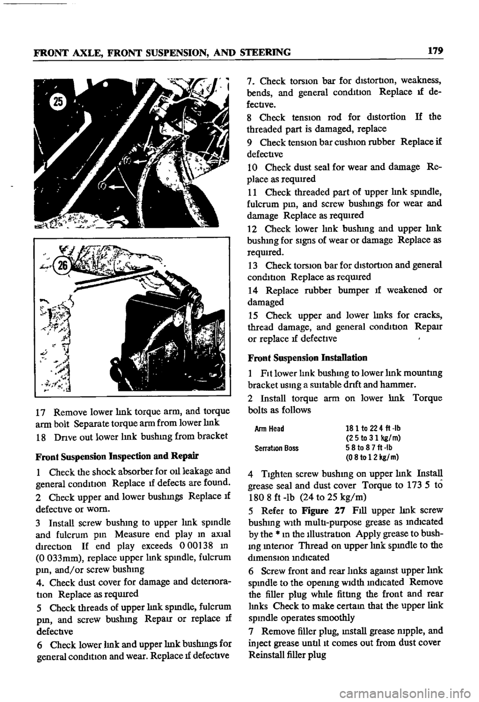
17
Remove
lower
lmk
torque
arm
and
torque
arm
bolt
Separate
torque
arm
from
lower
lmk
18
Dnve
out
lower
lmk
bushmg
from
bracket
Front
Suspension
Inspection
and
Repair
1
Check
the
shock
absorber
for
011
leakage
and
general
conditIon
Replace
1f
defects
are
found
2
Check
upper
and
lower
bushmgs
Replace
If
defective
or
worn
3
Install
screw
bushmg
to
upper
lmk
spmdle
and
fulcrum
pm
Measure
end
play
m
aXial
dIrection
If
end
play
exceeds
000
38
m
0
033mm
replace
upper
lmk
spmdle
fulcrum
pm
and
or
screw
bushmg
4
Check
dust
cover
for
damage
and
detenora
tIon
Replace
as
reqUIred
5
Check
threads
of
upper
lmk
spmdle
fulcrum
pm
and
screw
bushmg
RepaIr
or
replace
If
defective
6
Check
lower
lmk
and
upper
lmk
bushmgs
for
general
condition
and
wear
Replace
1f
defective
7
Check
torsion
bar
for
distortion
weakness
bends
and
general
conmtIon
Replace
If
de
fectIve
8
Check
tensIOn
rod
for
dIStortion
If
the
threaded
part
is
damaged
replace
9
Check
tenSiOn
bar
cushIOn
rubber
Replace
if
defective
10
Check
dust
seal
for
wear
and
damage
Re
place
as
requIred
11
Check
threaded
part
of
upper
lmk
spmdle
fulcrum
pm
and
screw
bushmgs
for
wear
and
damage
Replace
as
required
2
Check
lower
hnk
bushmg
and
upper
hnk
bushmg
for
SignS
of
wear
or
damage
Replace
as
reqwred
13
Check
torsIOn
bar
for
dlstorllon
and
general
condition
Replace
as
reqwred
14
Replace
rubber
bumper
If
weakened
or
damaged
15
Check
upper
and
lower
lmks
for
cracks
thread
damage
and
general
condition
RepaIr
or
replace
If
defectIve
Front
Suspension
Installation
1
Fit
lower
lmk
bushmg
to
lower
lmk
mountmg
bracket
usmg
a
SUItable
drlft
and
hanmIer
2
Install
torque
arm
on
lower
lmk
Torque
bolts
as
follows
181
to
224
fl
lb
25to31
kg
m
58
to
8
7
fl
Ib
08
to
12
kg
m
4
Tighten
screw
bushmg
on
upper
lmk
Install
grease
seal
and
dust
cover
Torque
to
173
5
to
1808
ft
lb
24
to
25
kg
m
5
Refer
to
Figure
27
Fill
upper
lmk
screw
bushmg
With
multi
purpose
grease
as
mdlcated
by
the
m
the
Illustration
Apply
grease
to
bush
mg
mtenor
Thread
on
upper
lmk
spmdle
to
the
dimenSIOn
mdIcated
6
Screw
front
and
rear
lInks
agaJnst
upper
hnk
spmdle
to
the
openmg
Width
mdlcated
Remove
the
filler
plug
while
fittIng
the
front
and
rear
lmks
Check
to
make
cectam
that
the
upper
link
spmdle
operates
smoothly
7
Remove
filler
plug
mstall
grease
mpple
and
inJect
grease
untIl
It
comes
out
from
dust
cover
Reinstall
filler
plug
Arm
Head
Serration
Boss
Page 186 of 252
FRONT
AXLE
FRONT
SUSPENSION
AND
STEERING
181
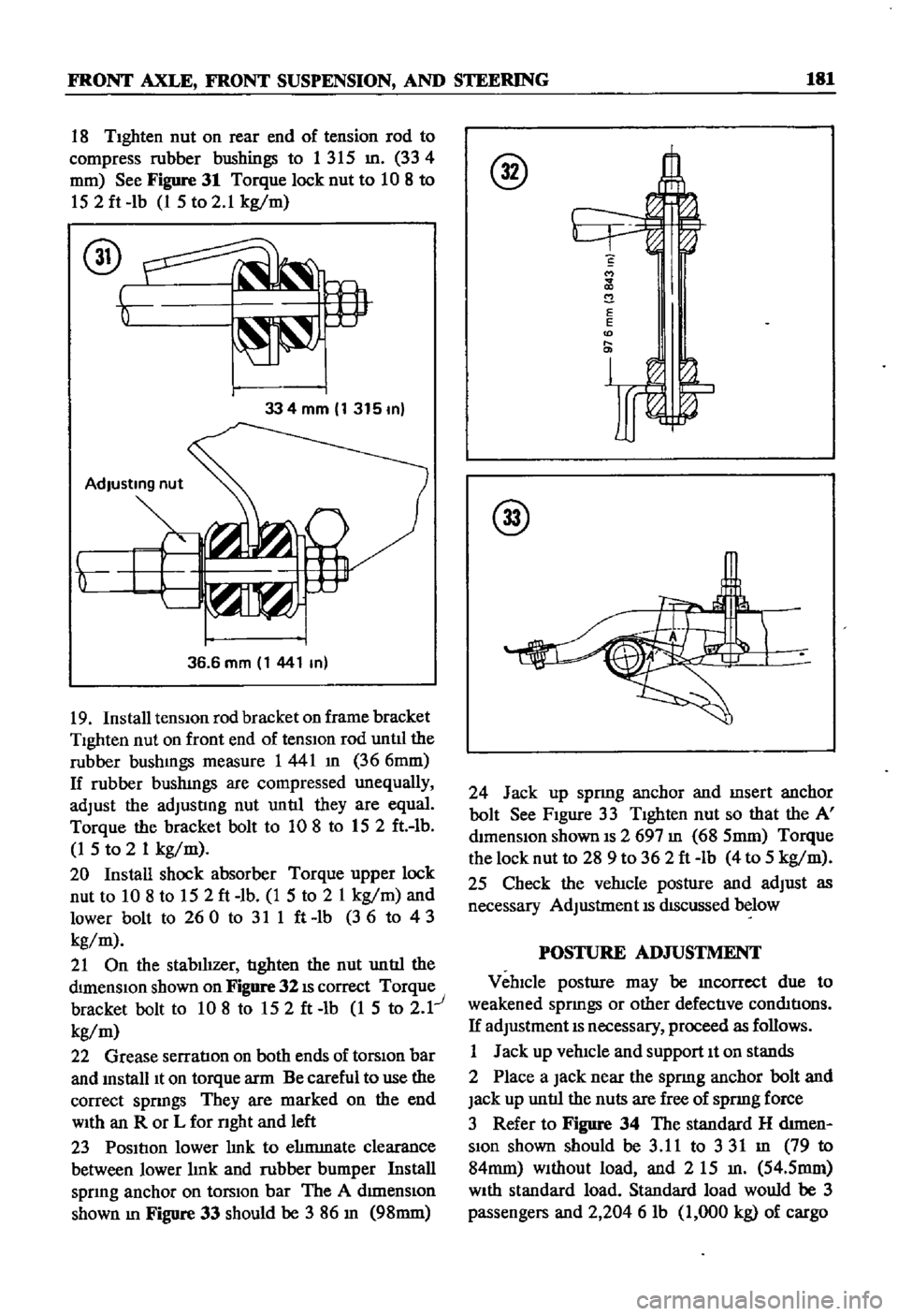
18
TIghten
nut
on
rear
end
of
tension
rod
to
compress
rubber
bushings
to
1
315
m
334
fi2
mm
See
Figure
31
Torque
lock
nut
to
10
8
to
152ft
lb
1
5
to
2
1
kg
m
334mm
1315m
36
6
mm
1
441
m
19
Install
tensiOn
rod
bracket
on
frame
bracket
Tighten
nut
on
front
end
of
tensIOn
rod
untll
the
rubber
bushmgs
measure
1441
m
366mm
If
rubber
bushmgs
are
compressed
unequally
adJust
the
adJusting
nut
until
they
are
equal
Torque
the
bracket
bolt
to
108
to
152
ft
lb
1
5
to
2
1
kg
m
20
Install
shock
absorber
Torque
upper
lock
nut
to
10
8
to
152ft
lb
1
5
to
2
1
kg
m
and
lower
bolt
to
260
to
311ft
lb
36
to
43
kg
m
21
On
the
stabilizer
tighten
the
nut
until
the
dimenSIOn
shown
on
Figure
32
IS
correct
Torque
bracket
bolt
to
10
8
to
152ft
lb
1
5
to
2
1
kg
m
22
Grease
serratIon
on
both
ends
of
torSiOn
bar
and
mstalllt
on
torque
arm
Be
careful
to
use
the
correct
spnngs
They
are
marked
on
the
end
WIth
an
R
or
L
for
nght
and
left
23
Position
lower
hnk
to
ehmmate
clearance
between
lower
hnk
and
rubber
bumper
Install
spnng
anchor
on
torsIOn
bar
The
A
dImenSiOn
shown
m
Figure
33
should
be
3
86
m
98mm
S
M
2
E
E
D
@
24
Jack
up
spnng
anchor
and
msert
anchor
bolt
See
Figure
33
Tighten
nut
so
that
the
A
mmenslon
shown
IS
2
697
m
68
5mm
Torque
the
lock
nut
to
28
9
to
362ft
lb
4
to
5
kg
m
25
Check
the
vehicle
posture
and
adJust
as
necessary
AdJustment
IS
dIScussed
below
POSTURE
AD
JUSTMENT
Vehicle
posture
may
be
mcorrcct
due
to
weakened
sprmgs
or
other
defective
conmtions
If
adJustment
IS
necessary
proceed
as
follows
1
Jack
up
vehicle
and
support
It
on
stands
2
Place
a
Jack
near
the
sprmg
anchor
bolt
and
Jack
up
until
the
nuts
are
free
of
spnng
force
3
Refer
to
Figure
34
The
standard
H
d1men
Slon
shown
should
be
3
11
to
331
m
79
to
84mm
Without
load
and
2
15
m
54
5mm
WIth
standard
load
Standard
load
would
be
3
passengers
and
2
204
6
lb
1
000
kg
of
cargo
Page 187 of 252
182
CHAPTER
TIllRTEEN
@
AdJust
the
anchor
bolt
adJustmg
nut
until
the
vehicle
posture
IS
correct
One
complete
turn
of
the
nut
will
change
the
vertIcal
measurement
by
approXlmately
0
133
in
3
Smm
WHEEL
AUGNMENT
Due
to
the
speclahzed
eqwpment
required
wheel
ahgnment
should
be
referred
to
a
Datsun
dealer
or
a
wheel
alignment
specIahst
The
fol
lowmg
specmcatIons
apply
to
the
pick
up
Caster
Camber
Kmg
Pm
Inclmatlon
Toe
In
1
50
1
15
6015
o
0787
to
0
1181
In
2
to
3mm
360
31
Steenng
Angle
Inner
Steenng
Angle
Outer
STEERING
SYSTEM
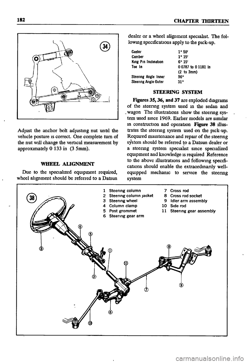
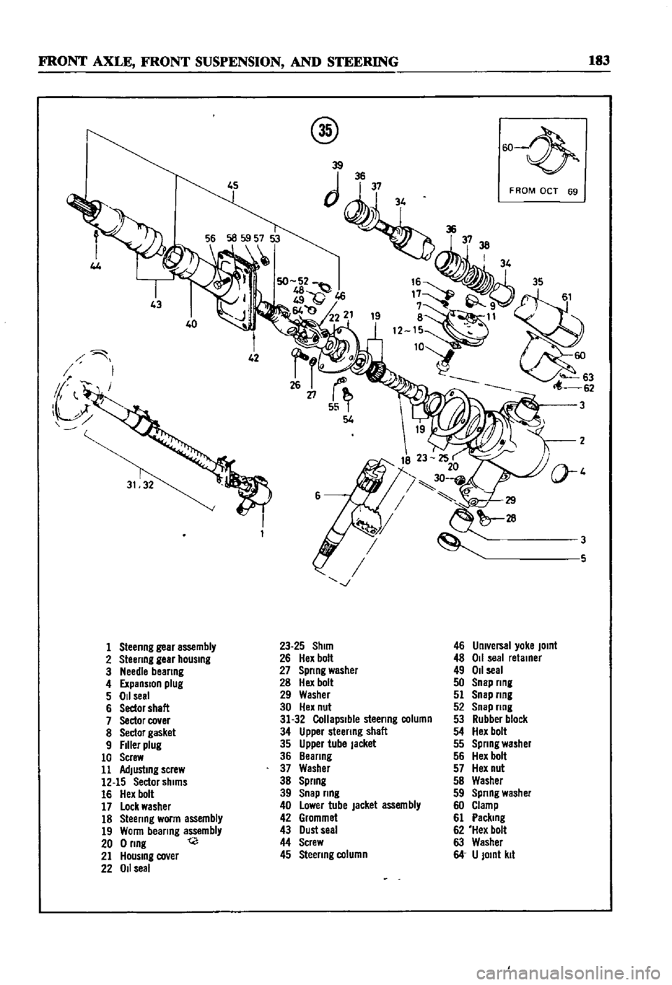
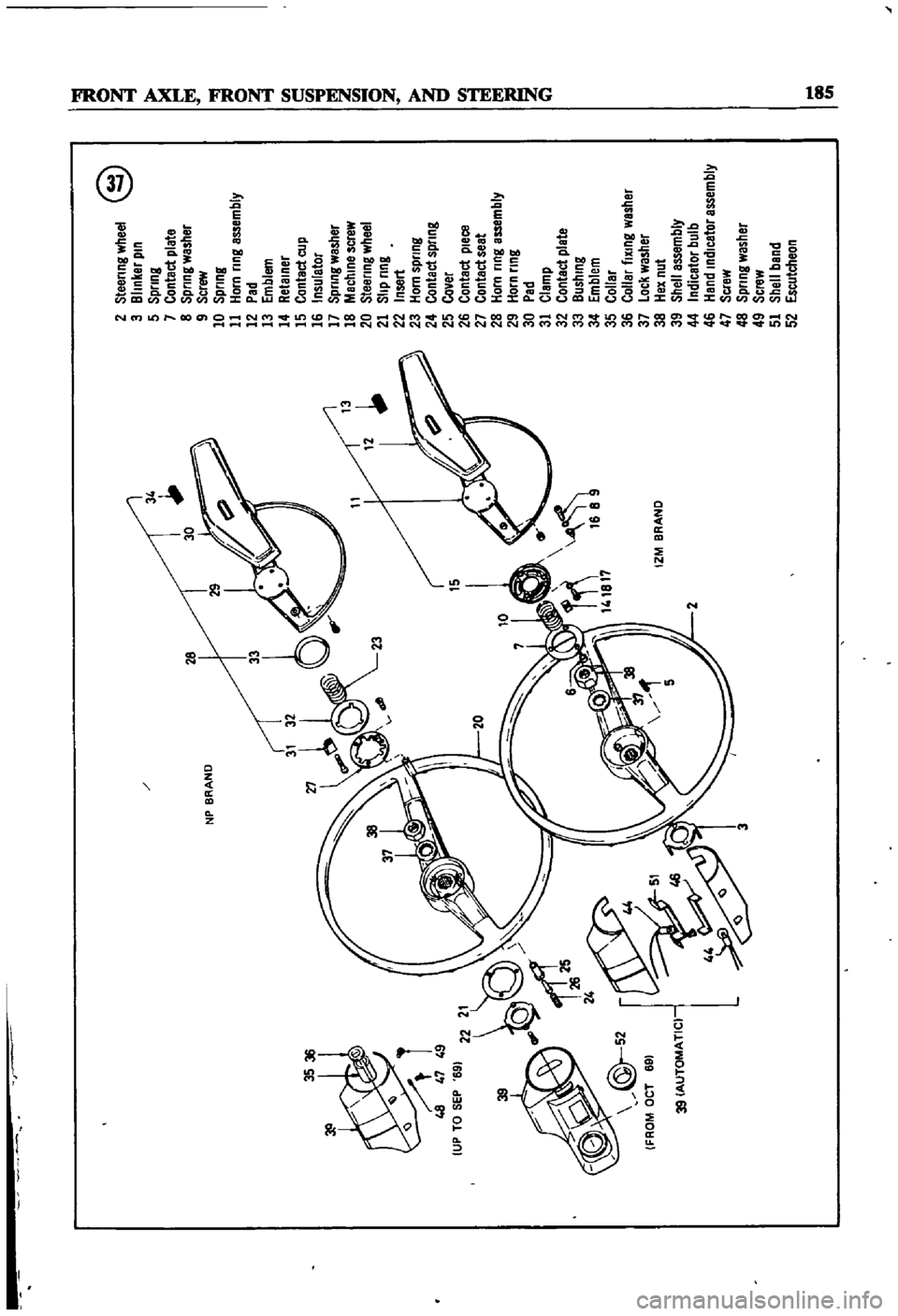
Figures
35
36
nnd
37
are
exploded
magrams
of
the
steenng
system
used
m
the
sedan
and
wagon
The
illustratIons
show
the
steenng
sys
tem
used
smce
1969
Earher
models
are
SImllar
m
constructiOn
and
operatIon
Figure
38
illus
trates
the
steenng
system
used
on
the
pick
up
ReqUIred
mamtenance
and
repaJr
of
the
steenng
system
should
be
referred
o
a
Datsun
dealer
or
a
steermg
system
specialISt
smce
specialized
eqwpment
and
knowledge
IS
required
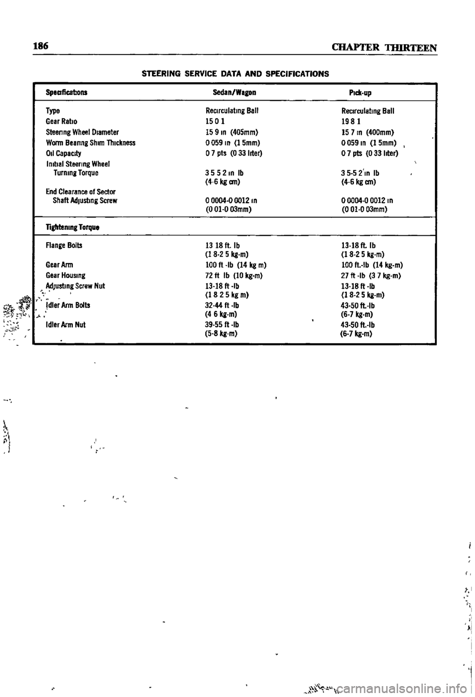
Reference
to
the
above
Illustrations
and
followmg
specm
cations
should
enable
the
extraordmanly
well
equipped
mechanIC
to
serVice
the
steermg
system
1
Steenng
column
2
Steermg
column
Jacket
3
Steenng
wheel
4
Column
clamp
5
Post
grommet
6
Steenng
gear
arm
7
Cross
rod
8
Cross
rod
socket
9
Idler
arm
assembly
10
Side
rod
11
Steermg
gear
assembly
Page 188 of 252
FRONT
AXLE
FRONT
SUSPENSION
AND
STEERING
183
4J
40
1
Steenng
gear
assembly
2
Steenng
gear
hOUSing
3
Needle
beanng
4
ExpanSion
plug
5
011
seal
6
Sedor
shaft
7
Sector
cover
8
Sector
gasket
9
Filler
plug
10
Screw
11
Adjusting
screw
12
15
Sector
shims
16
Hex
bolt
17
Lock
washer
18
Steenng
worm
assembly
19
Wonn
bearing
assembly
200nng
t
21
HOUSing
cover
22
011
seal
@
w
39
JJii
3738
I
34
8
11
12
W63
62
23
25
Shim
26
Hex
bolt
27
Spnng
washer
28
Hex
bolt
29
Washer
30
Hex
nut
31
32
Collapsible
steenng
column
34
Upper
steenng
shaft
35
Upper
tube
Jacket
36
Beanng
37
Washer
38
Spnng
39
Snap
nng
40
Lower
tube
jacket
assembly
42
Grommet
43
Dust
seal
44
Screw
45
Steenng
column
F
ROM
OCT
69
3
3
5
46
Umversal
yoke
JOint
48
011
seal
retainer
49
011
seal
50
Snap
nng
51
Snap
nng
52
Snap
nng
53
Rubber
block
54
Hex
bolt
55
Spnng
washer
56
Hex
bolt
57
Hex
nut
5B
Washer
59
Spnng
washer
60
Clamp
61
Paclung
62
Hex
bolt
63
Washer
64
U
JOint
kit
Page 190 of 252
NP
BRAND
3536
48
47
49
UP
TO
SEP
69
15
10
l
f
J
r
1
L
IZM
BRAND
39
39
AUTOMATIC
2
Steering
wheel
@
3
Blinker
pin
5
Spring
7
Contact
plate
8
Spring
washer
9
Screw
10
Spring
11
Horn
ring
assembly
12
Pad
13
Emblem
14
Retainer
15
Contact
cup
16
Insulator
17
Spring
washer
18
Machine
screw
20
Steering
wheel
21
Slip
ring
22
Insert
23
Horn
spring
24
Contact
spring
25
Cover
26
Contact
pleca
27
Contact
seat
28
Horn
ring
assembly
29
Horn
ring
30
Pad
31
Clamp
32
Contact
plate
33
Bushing
34
Emblem
35
Collar
36
Collar
fiXing
washer
37
Lock
washer
38
Hex
nut
39
Shell
assembly
44
Indicator
bulb
46
Hand
indicator
assembly
47
Scraw
48
Spring
washer
49
Screw
51
Shell
band
52
Escutcheon
o
I
l
I
l
i
J
I
Ci
l
QD
II
L
Page 191 of 252
186
CHAPTER
TIURTEEN
STEERING
SERVICE
DATA
AND
SPECIFICATIONS
r
SpeaficatJons
Sedan
Wagon
P1c11
up
Type
Reclrculatmg
Ball
Reclrculatmg
Ball
Gear
Ratio
1501
1981
Steenng
Wheel
Diameter
159m
405mm
157m
400mm
Wonn
Beanng
Shim
Thickness
0059
m
1
5mm
0059
m
1
5mm
011
CapacJ
y
o
7
pts
0
33
hter
o
7
pts
0
33
hter
Imtlal
Steering
Wheel
Turnmg
Torque
3552mlb
3
5
5
2
In
Ib
4
6
kg
an
4
6
kg
an
End
Clearance
of
Sector
Shaft
AdJustmg
Screw
o
0004
0
0012
m
00004
00012
m
0
01
0
03mm
0
01
0
03mm
Tiglrtenlng
Torque
Flange
Bolts
13
18
ft
Ib
13
18
ft
Ib
1
8
2
5
kg
m
1
8
2
5
kg
m
Gear
Ann
100
ft
Ib
14
kg
m
100
ft
lb
14
kg
m
Gear
Housmg
72
ft
Ib
10
kg
m
27
ft
Ib
3
7
kg
m
dJustmg
Screw
Nut
13
18
ft
Ib
13
18
ft
Ib
y
1
8
2
5
kg
m
1
8
2
5
kg
m
dler
Ann
Bolts
32
44
ft
rb
43
50
ft
Ib
4
6
kg
m
6
7
kg
m
Idler
Arm
Nut
39
55
ft
Ib
43
50
ft
lb
5
8
kg
m
6
7
kg
m
St
I
j
i
I
i
1
l
I
I
Page 246 of 252
240
INDEX
SpecIfications
and
service
data
144
Installation
58
Troubleshootmg
16
Removal
and
disassembly
42
85
Transverse
hnk
sedan
and
wagon
174
Repair
and
reassembly
85
Troubleshootmg
Wheel
ahgnment
Brakes
16
Pick
up
182
Chargmg
system
12
Sedan
and
wagon
174
Clutch
15
Wheel
bearIngs
sedan
and
wagon
177
Engme
13
Wheel
bearIngs
and
seals
sedan
f55
156
EqUipment
9
Wheel
cyhnders
pick
up
196
Exhaust
emiSSIOn
control
15
Wheel
hub
and
bearIng
sedan
and
wagon
Fuel
system
14
BearIng
adjustment
177
Igrutlon
system
13
InspectIOn
and
repair
172
Starter
10
Installation
172
SteerIng
and
suspension
16
Removal
168
Tire
wear
analysIs
17
Wheels
TransmiSSion
16
Ahgnment
pick
up
182
Wheel
balancmg
18
Ahgnment
sedan
and
wagon
174
Trunk
hd
228
230
Balancmg
18
Wmdshleld
washers
V
Descnptlon
210
Valves
Exploded
view
218
Adjustment
59
Wmdshleld
WIperS
Clearance
adjustment
25
DeSCrIption
210
DesCrIption
34
Exploded
view
1969
1972
216
Inspection
47
Wmng
diagrams
Rocker
pivot
reassembly
54
Pick
up
222
Voltage
regulator
104
Sedan
and
wagon
automatic
transmiSSIOn
221
Sediln
and
wagon
manual
transmission
220
W
Wmng
harnesses
Pick
up
206
207
Water
pump
Sedan
205
Exploded
views
86
88
Wagon
206
l
Page 252 of 252
r
t
i
f
If
t
I
DAnUN
SE
1
5
10
AN
l
@
0
i1
rtr
JM
OIi
l
jj
I
I
if
J
I
f
lJ
I
I
f
I
I
tflr
f1
h
f
I
v
L
7
I
l1It
l
I
fIr
t
I
r
II
to
E
m
PAIIt
I
lANI
X
I
I
PICK
UP
1968
1972
t
t
I
0
l
1
j
f
r
t
g
I
I
0
r
r
This
completely
new
edition
is
Clymer
s
first
covering
late
model
Dat
ouns
The
popular
pick
up
truck
a
best
seller
in
its
own
is
also
included
Material
has
been
pai
stakingly
prepared
by
a
top
technical
writer
and
tlien
carefully
edited
Major
sections
include
Periodic
Maintenance
Trouble
hooting
Tune
up
Lubrication
Engine
Fuel
System
Cooling
Ele
rical
System
Emissio
ontrols
Clytch
Transmission
and
Drive
shaft
Differential
Rear
Axle
Steering
rakes
1
Body
Wbiie
a
f
re
airs
on
advan
lMI
eauipment
such
as
sophisticated
1
II
emissi
ontruls
are
beyond
e
mechanics
the
simple
tests
I
f
l
1
1
and
t
ubl
shooting
measures
ndtided
can
help
diagnose
problems
Wher
r
lrs
are
practical
cr
mplete
informatfon
is
given
Equally
im
t
nt
ho
gh
thi
autho
frequently
includes
cautioning
gotes
1
f
I
where
proCeduljes
are
confusing
and
occasionally
suggests
that
here
s
b
I
t
1
t
I
a
10
1requ
ring
uea
er
attentloru
Ii
l
I
As
in
ail
C
ymer
books
the
goal
has
j
I
I
1
be
n
to
kelp
owners
understand
th
ir
far
owpr
repair
costs
and
generaUi
i
lnprove
automotive
sat
isfadion
O
Jr
200
other
utomotive
and
motcwc
y
c1e
itles
deal
with
re
pairl
performance
tuning
and
nostalgia
Ask
for
them
at
leading
J
book
stores
and
auto
supply
outlets
I
CLY
PUBLI
ATll
LO
MGELES
1
6
r
I
l
t