1968 DATSUN 510 lights
[x] Cancel search: lightsPage 15 of 252

10
CHAPTER
THREE
pressure
bUllt
up
In
each
cylInder
The
readIngs
when
properly
Interpreted
IndIcate
general
cyl
Inder
and
valve
condltlOn
Vacuum
Gauge
The
vacuum
gauge
IS
easy
to
use
but
dIfficult
for
an
Inexpenenced
mechanIC
to
Interpret
The
results
when
conSIdered
WIth
other
findIngs
can
prOVIde
valuable
clues
to
pOSSIble
trouble
Connect
the
vacuum
gauge
WIth
a
T
connec
tIon
In
the
hose
from
the
carburetor
to
the
vacuum
advance
on
the
dIstnbutor
Start
the
engme
and
let
It
warm
up
thoroughly
Vacuum
readIng
should
be
steady
at
18
22
Inches
NOTE
Subtract
1
Inch
from
reading
for
every
1000
feet
of
altitude
Figure
1
shows
numerous
tYPical
readIngs
WIth
InterpretatIons
Results
are
not
conclusive
WIthout
companng
to
other
tests
such
as
com
preSSIOn
readIngs
Fuel
Pressure
Gauge
ThIS
Instrument
IS
VItal
for
evaluatIng
fuel
pump
performance
Often
a
vacuum
gauge
and
fuel
pressure
gauge
are
combIned
Dwell
Meter
A
dwell
meter
measures
the
dIstance
In
de
grees
of
cam
rotatIon
that
the
breaker
pOInts
remaIn
closed
while
the
engme
IS
runnIng
SInce
thIS
angle
IS
determmed
by
breaker
pOInt
gap
the
dwell
angle
IS
an
accurate
IndIcatIon
of
pOInt
gap
Many
tachometers
Intended
for
tunIng
and
testIng
Incorporate
a
dwell
meter
as
well
Follow
the
manufacturer
s
InstructIon
to
measure
dwell
on
the
Datsun
Tachometer
A
tachometer
IS
essential
for
tunIng
Datsuns
WIth
exhaust
emission
control
deVices
IgmtIOn
turung
and
carburetor
adjustments
must
be
per
formed
at
the
specified
Idle
speed
The
best
In
strument
for
thIS
purpose
IS
one
WIth
a
range
of
0
1
000
or
0
2
000
rpm
Extended
range
0
6
000
or
8
000
Instruments
lack
accuracy
at
lower
speeds
The
InStrument
should
be
capable
of
detecting
changes
of
25
rpm
Stroboscopic
Timing
Light
ThIS
Instrument
pernuts
accurate
IgnitIon
tImIng
By
f1ashmg
a
bght
at
the
preCISe
Instant
cylInder
No
1
fires
the
posItIon
of
the
crank
shaft
pulley
at
that
Instant
can
be
seen
Marks
on
the
pulley
bne
up
With
a
reference
pOInter
on
the
block
dunng
the
tIming
procedure
SUltable
bghts
are
neon
bulb
types
and
xenon
strobe
hghts
Neon
tunmg
bghts
are
ddticult
to
see
and
must
be
used
in
dImly
bt
areas
Xenon
strobe
bghts
can
be
used
In
bnght
sunbght
Use
the
bght
accordIng
to
the
manufacturer
s
InStruC
tIons
Exhaust
Analyzer
Of
all
Instruments
descnbed
here
this
IS
the
least
bkely
to
be
owned
by
a
home
mechanic
One
Instrument
samples
the
exhaust
gases
from
the
taIlpIpe
and
measures
the
thermal
conduc
tIVIty
of
the
exhaust
gas
SInce
different
gases
conduct
heat
at
varYIng
rates
thermal
conduc
tIVIty
of
the
exhaust
IS
a
good
IndIcatIon
of
gases
present
This
Instrument
IS
VItal
for
accurately
checkIng
the
effectIveness
of
exhaust
emIssion
control
adjustments
but
IS
too
expenSIve
for
an
amateur
mechanIC
to
conSIder
buying
STARTER
Starter
system
troubles
are
relatIvely
easy
to
ISolate
The
followmg
are
common
symptoms
and
cures
1
Engme
cranks
very
slowly
or
not
at
all
Turn
on
the
headhghts
If
the
bghts
are
very
dun
most
likely
the
battery
or
the
connecting
WireS
are
at
fault
Check
the
battery
using
the
pro
cedures
descnbed
in
the
Tune
up
chapter
Check
wmmgfur
e
s
wom
andd
connectIom
H
the
battery
and
connectIng
WIres
check
good
turn
the
headlIghts
on
and
try
to
crank
the
engIne
H
the
lIghts
dIDl
drastIcally
the
starter
is
probably
shorted
to
ground
Remove
the
starter
and
test
it
usmg
the
procedures
gIven
in
Chapter
NIne
If
the
lights
remain
bnght
or
dun
slIghtly
when
crankIng
the
engme
the
trouble
may
be
in
the
starter
solenOId
or
wmng
To
ISolate
the
trouble
short
the
two
large
solenoid
ternunals
together
not
to
ground
if
the
starter
cranks
normally
check
the
solenoid
and
wmng
up
to
the
Page 18 of 252

TROUBLESHOOTING
13
trouble
may
also
be
worn
bearings
Remove
the
alternator
and
repair
ENGINE
These
procedures
assume
the
starter
cranks
the
engme
over
normally
If
not
refer
to
Starter
section
m
this
chapter
1
Engme
won
t
start
Could
be
caused
by
the
IgOltlon
or
fuel
problems
First
determine
If
high
voltage
to
spark
plug
occurs
To
do
thiS
dISconnect
one
of
the
spark
plug
wires
Hold
the
exposed
wrre
termlOal
y
to
Y2
lOch
from
ground
any
metal
in
engine
com
partment
With
an
msulated
screwdriver
Crank
the
engme
over
If
sparks
do
not
Jump
to
ground
or
the
sparks
are
very
weak
the
trouble
may
be
10
the
IgnitIOn
system
See
Ignition
System
Trou
bleshootmg
to
further
check
If
sparks
occur
properly
the
trouble
may
be
10
the
fuel
system
See
Fuel
System
Troubleshootmg
2
Engme
misses
steadily
Remove
one
spark
plug
wrre
at
a
tune
and
ground
the
wrre
If
engme
mISs
increases
that
cyhnder
was
work
109
properly
Reconnect
the
wire
and
check
the
others
When
a
wire
IS
dIs
connected
and
engme
miss
remams
the
same
that
cylinder
IS
not
finng
Check
spark
as
descnbed
10
Step
1
If
no
spark
occurs
for
one
cyhnder
only
check
dlStnbutor
cap
wrre
and
spark
plug
If
spark
occurs
prop
erly
check
compressIOn
and
mtake
maOlfold
vacuum
to
ISolate
the
trouble
3
Engme
misses
erratlcally
at
all
speeds
Interrmttent
trouble
can
be
difficult
to
find
It
could
be
ill
the
Ignition
system
exhaust
system
or
fuel
system
Follow
troubleshooting
proce
dures
for
these
systems
carefully
to
isolate
the
trouble
4
Engme
misses
at
Idle
only
Trouble
could
exist
anywhere
ill
IgOltlon
system
Follow
Ignition
TroubleshootlOg
procedure
care
fully
Trouble
could
also
eXist
10
the
carburetor
Idle
crrcult
Check
Idle
mIXture
adjustment
and
check
for
restnctions
m
the
idle
crrcUlt
5
Engme
misses
at
high
speed
only
Problems
could
be
ill
the
fuel
or
IgOltlon
systems
heck
accelerator
pump
operation
fuel
pump
dehvery
fuel
hnes
etc
as
descnbed
under
Fuel
System
Troubleshootillg
Also
check
spark
plugs
and
wrres
6
Low
performance
at
all
speeds
poor
acceleratIOn
Trouble
usually
ill
IgOltlon
or
fuel
system
Check
each
With
the
appropnate
troubleshooting
pro
cedure
7
ExceSSive
fuel
consumptIOn
Could
be
caused
by
a
Wide
variety
of
seemmgly
unrelated
factors
Check
for
clutch
shppage
brake
drag
defective
wheel
beanngs
or
poor
front
end
alignment
Check
IgOltlOn
system
and
fuel
system
8
011
pressure
lamp
does
not
light
when
IgmtlOn
switch
IS
on
Check
the
alternator
warning
lamp
If
it
ISn
t
on
either
go
to
Step
1
Chargmg
System
Trouble
shootlOg
If
only
the
oil
pressure
lamp
IS
off
open
the
englOe
compartment
hd
and
locate
the
oil
pressure
sender
on
the
block
near
the
oil
filter
Make
sure
the
wrre
is
connected
to
the
sender
and
makmg
good
contact
Pull
the
wrre
off
and
ground
it
If
the
lamp
hghts
replace
the
sender
If
the
lamp
does
not
light
replace
the
lamp
9
011
pressure
lamp
lights
or
flickers
when
engme
IS
runmng
Indicates
low
or
complete
loss
of
oil
pressure
Stop
the
englOe
unmedmtely
coast
to
a
stop
With
the
clutch
dISengaged
Tlus
may
simply
be
caused
by
a
low
oil
level
or
an
overheatmg
en
glOe
Check
the
oil
level
and
fan
belt
tensIOn
Check
for
a
shorted
oil
pressure
sender
with
an
ohmmeter
or
a
contlOulty
tester
Remove
and
clean
the
oil
dipstick
and
check
oil
level
and
condition
RepleOlsh
or
replace
the
oil
as
re
qurred
Listen
for
unusual
nOISes
mdlcatmg
dam
aged
beanngs
etc
Do
not
re
start
the
engine
until
you
know
why
the
hght
went
on
and
are
sure
that
the
problem
has
been
corrected
IGNITION
SYSTEM
This
procedure
assumes
the
battery
IS
ill
good
enough
condition
to
crank
the
engme
at
a
normal
rate
Page 153 of 252

148
CHAPTER
ELEVEN
1
Insert
key
in
IgnItion
switch
and
turn
to
first
posltlon
2
Depress
accelerator
pedal
fully
LISten
for
the
solenOId
to
click
If
a
clIck
is
heard
the
solenoid
is
operating
correctly
3
Replace
solenoid
if
click
IS
not
heard
Before
replacing
solenoid
dram
apprOlumately
2
pInts
of
transmission
011
from
tranSmISsion
Re
fill
when
solenoid
replacement
is
complete
4
If
solenoId
IS
operatlng
correctly
but
trouble
persISts
check
WIres
for
continuity
With
electri
cal
tester
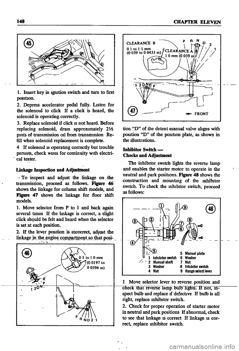
Linkage
Inspection
and
Adjustment
To
inspect
and
adjust
the
linkage
on
the
transmission
proceed
as
follows
Figure
4
j
shows
the
linkage
for
column
shift
models
and
Figure
47
shows
the
lInkage
for
floor
shift
models
1
Move
selector
from
P
to
1
and
back
again
several
tImes
If
the
lInkage
is
correct
a
slight
click
sh
uld
be
felt
and
heard
when
the
selector
is
set
at
each
position
2
If
the
lever
position
is
mcorrect
adjust
the
lin
age
in
t
ie
ngin
C
Q1I1
lT
me
t
s9
mat
f46
OSIoI0mm
00197
to
mJ
r2
oN
k
@
FRONT
tion
D
of
the
detent
manual
valve
alignS
with
posItion
D
of
the
pOSItIon
plate
as
shown
in
the
illustrations
Inhibitor
Switc
h
Checks
and
Adjustment
The
inhibItor
SWitch
lights
the
reverse
lamp
and
enables
the
starter
motor
to
operate
in
the
neutral
and
park
positIons
Figure
48
shows
the
construction
and
mountlng
of
the
InhibItor
SWitch
To
check
the
mhIbltor
switch
proceed
as
follows
r
I
5
1
InhIbitor
switch
2
Menual
shalt
3
Washer
4
Nut
5
Manual
plate
6
Washer
7
Nut
8
Inhibitor
switch
9
Range
select
Iner
1
Move
selector
lever
to
reverse
position
and
clieck
that
reverse
lamp
bun
lignts
If
not
in
spect
bulb
and
replace
1f
defectlve
If
bulb
is
all
right
replace
mhibItor
switch
2
Check
for
proper
operation
of
starter
motor
in
neutral
and
park
positions
If
abnormal
check
to
see
that
lInkage
IS
correct
If
linkage
IS
cor
rect
replace
Inhibitor
SWitch
Page 244 of 252

138
INDEX
H
OIl
pump
Descnptlon
36
Handbrake
Exploded
view
29
Adjustment
202
Inspection
and
repaIr
28
Cable
removal
front
sedan
and
wagon
197
Installation
58
Cable
removal
rear
pick
up
201
Removal
28
40
Cable
removal
rear
sedan
and
wagon
197
Cross
rod
removal
wagon
201
Exploded
views
198
200
p
Inspection
and
repair
201
Installation
201
Penodlc
mamtenance
Headlights
MaIntenance
mtervals
chart
7
Bulb
replacement
210
Penodlc
checks
6
Descnptlon
210
Recommended
lubncants
8
Exploded
view
219
Routine
checks
6
HeatIng
system
Piston
nngs
Descnptlon
210
Exploded
view
pick
up
213
Inspection
50
Exploded
VIews
sedan
and
wagon
214
215
Removal
45
Hood
lock
control
RIng
gap
50
Exploded
View
pick
up
225
Pistons
Descnptlon
34
Exploded
VIew
sedan
and
wagon
226
Inspection
50
Reassembly
54
Igmtlon
coil
111
R
Igmtlon
system
Tlmmg
23
Radiator
Troubleshooting
13
Exploded
view
90
Instrument
meters
and
panels
Removal
and
replacement
90
Descnptlon
210
Rear
axle
pick
up
Exploded
View
pick
up
213
Axle
case
166
Exploded
view
sedan
and
wagon
Inspection
and
mstalIatlon
164
1970
1972
212
Removal
164
Exploded
view
sedan
and
wagon
Sectional
view
163
through
1969
211
Rear
axle
wagon
Intake
manifold
Disassembly
158
Descnptlon
36
Exploded
view
158
Removal
42
Inspection
and
reassembly
160
InstallatIOn
160
Removal
158
M
Rear
axle
and
suspenSion
sedan
Exploded
view
152
153
Mam
beanngs
52
Inspection
and
repaIr
154
MaIntenance
penodlc
6
8
InstalIatlon
154
Master
cylInder
Removal
151
Exploded
vIew
smgle
188
Rear
spnngs
pick
up
166
Exploded
view
tandem
189
Rear
spnngs
wagon
161
Inspection
and
repllIr
188
Rear
axle
shaft
sedan
155
156
Reassembly
and
InstalIatlon
190
Rear
suspension
arm
sedan
155
Removal
and
disassembly
188
Rear
suspenSion
pick
up
Modelldentdicatlon
1
Exploded
view
166
Inspection
and
repllIr
167
InstalIatlon
167
0
Rear
spnngs
166
Removal
165
011
filler
30
Spnngs
166
d
43
Torques
67