1968 DATSUN 510 differential
[x] Cancel search: differentialPage 5 of 252
CHAPTER
TWELVE
DIFFERENTIAL
REAR
AXLE
AND
REAR
SUSPENSION
149
DIfferentIal
Rear
axle
and
suspension
Codspnng
Shock
absorber
Rear
suspensIOn
arm
Rear
axle
shaft
Wheel
beanngs
Seals
Rear
spnng
Axle
case
SpecificatIons
CHAPTER
THIRTEEN
FRONT
AXLE
FRONT
SUSPENSION
AND
STEERING
168
Wheel
hub
and
bearmg
StabilIzer
TenSion
rod
Spnng
and
strut
assembly
Transverse
lInk
Lower
ball
Jomt
Front
suspension
adjustment
Wheel
alignment
Posture
adJustment
Steenng
system
SpeCificatIons
CHAPTER
FOURTEEN
BRAKES
187
Brake
pedal
Master
cylInder
Front
diSC
brakes
Rear
brakes
Front
drum
brakes
Wheel
cylInders
Brake
system
bleedIng
Handbrake
Service
data
and
speCificatIons
CHAPTER
FIFTEEN
BODY
ELECTRICAL
SYSTEM
Wmng
SWitches
and
fuses
Instrument
meters
and
panels
Heater
205
Wmdshleld
wipers
Wmdslueld
washers
Headlamps
WIrIng
diagrams
CHAPTER
SIXTEEN
BODY
223
Front
body
trIm
Bumpers
Hood
lock
control
Doors
Door
locks
and
regulators
Trunk
lId
and
rear
bumper
Seats
Tad
gate
INDEX
235
I
Page 154 of 252
CHAPTER
TWELVE
DIFFERENTIAL
REAR
AXLE
AND
REAR
SUSPENSION
The
dIfferential
rear
axle
and
rear
suspen
sIon
dIffer
for
the
various
models
ThIS
chapter
deals
WIth
each
separately
Due
to
the
need
for
SpecIal
tools
and
exper
Ience
to
dIsassemble
and
repaIr
these
unItS
the
followmg
procedures
generally
cover
removal
InspectIon
and
replacement
only
If
mechanIcal
dIfficultIes
eXIst
WIthIn
the
dIfferentIal
and
rear
axle
components
refer
servIce
and
repair
to
a
Datsun
dealer
or
competent
garage
DIFFERENTIAL
SEDAN
The
cast
Iron
dIfferentIal
assembly
used
in
the
sedan
is
shown
in
Figure
1
next
page
Proper
lubncatlOn
of
the
gear
housmg
IS
essen
tIal
Check
lubncant
every
3
000
mlles
and
re
plenISh
as
necessary
Drain
and
refill
lubncant
at
least
every
30
000
miles
Differential
Removal
Sedan
1
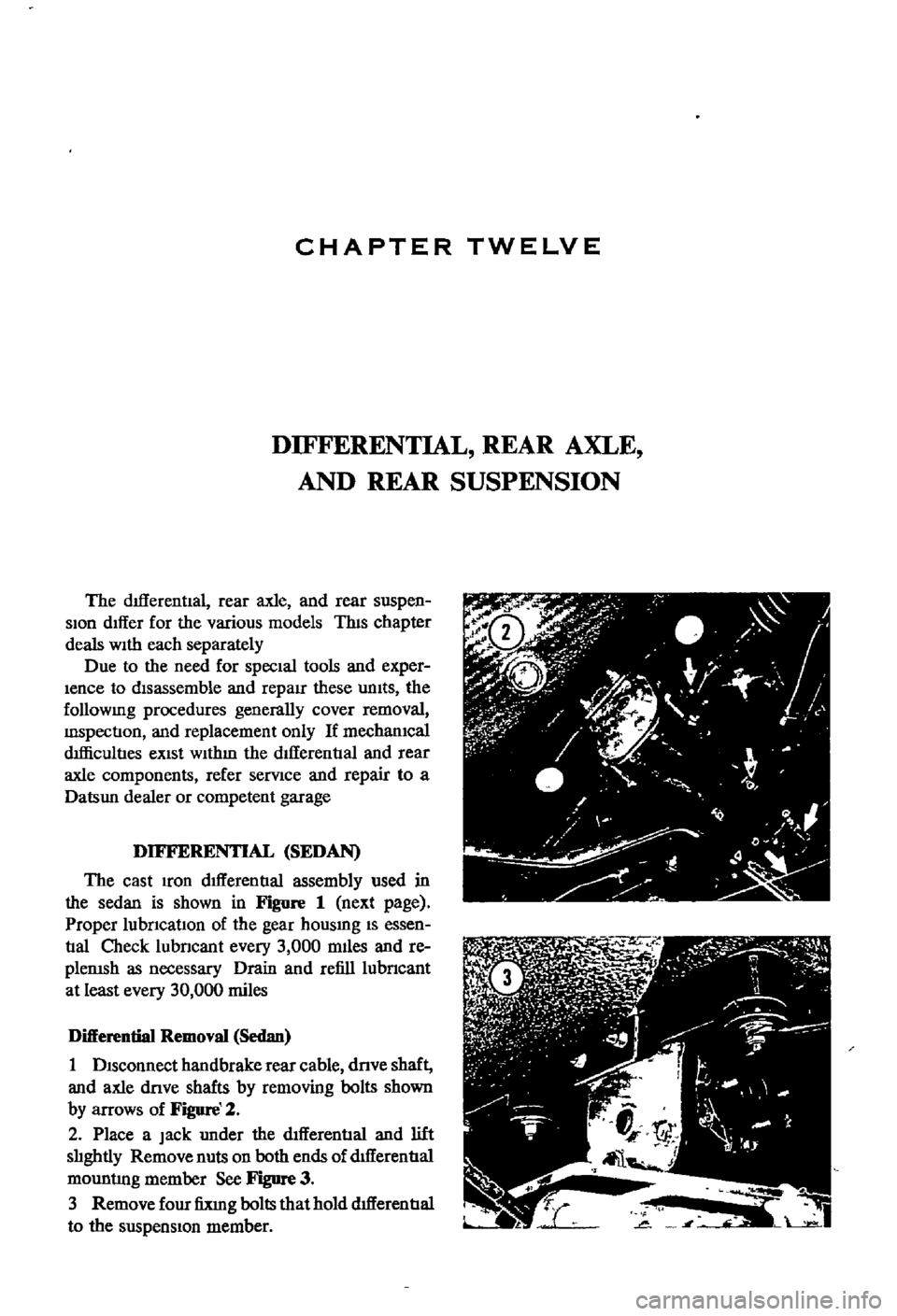
DISconnect
handbrake
rear
cable
dnve
shaft
and
axle
dove
shafts
by
removing
bolts
shown
by
arrows
of
Figure
2
2
Place
a
Jack
under
the
dIfferential
and
lift
slIghtly
Remove
nuts
on
both
ends
of
dtfferentIal
mountlng
member
See
Figure
3
3
Remove
four
fixIng
bolts
that
hold
dIfferentIal
to
the
suspensIon
member
Page 156 of 252

DIFFERENTIAL
REAR
AXLE
AND
REAR
SUSPENSION
151
4
Lower
the
Jack
and
r
move
dIfferentIal
from
rear
of
vehIcle
See
Figure
4
After
removal
sup
port
suspensIon
member
wIth
a
stand
to
prevent
distortlon
and
damage
to
the
Insulators
Differential
Inspection
Sedan
The
followmg
mspectIon
can
be
done
WIthout
disassembly
of
the
dIfferential
If
abnormalitIes
or
damage
eXiSts
refer
further
servIce
and
reparr
to
your
dealer
1
Check
the
tooth
contact
pattern
With
lead
oXide
at
two
or
three
pomts
after
removmg
rear
cover
Refer
to
Figure
5
which
shows
the
cor
rect
contact
pattern
If
the
contact
pattern
IS
m
correct
dIsassembly
and
adjustment
of
dIffer
entlalls
reqUIred
CD
TOE
HEEL
DRIVE
SIDE
HEEL
COAST
SIDE
2
Use
a
dIal
mdtcator
to
measure
backlash
be
tween
the
dnve
gear
and
pmIOn
Backlash
should
be
0
0039
to
0
0079
m
0
10
to
o
20mm
Check
all
gear
teeth
for
damage
and
cracks
3
Check
runout
at
the
rear
of
the
dnve
gear
If
the
tooth
contact
pattern
or
backlash
IS
ab
normal
Runout
should
be
less
than
00031
m
0
08mm
See
Figure
6
4
Rotate
the
gears
and
lIsten
for
SignS
of
de
fective
bearmgs
If
noises
are
eVIdent
the
dIf
ferential
must
be
dIsassembled
and
repaired
CD
Diflerentiallnstallation
Sedan
1
Mount
the
dIfferentIal
assembly
to
the
rear
suspensIOn
member
2
FIt
the
dIfferentIal
mountlng
member
to
the
fittmg
hole
by
pushIng
It
forward
with
a
bar
Torque
the
nuts
to
61
ft
lb
8
5
kg
m
3
Install
axle
dnve
shafts
dnve
shaft
and
handbrake
rear
cable
REAR
AXLE
AND
SUSPENSION
SEDAN
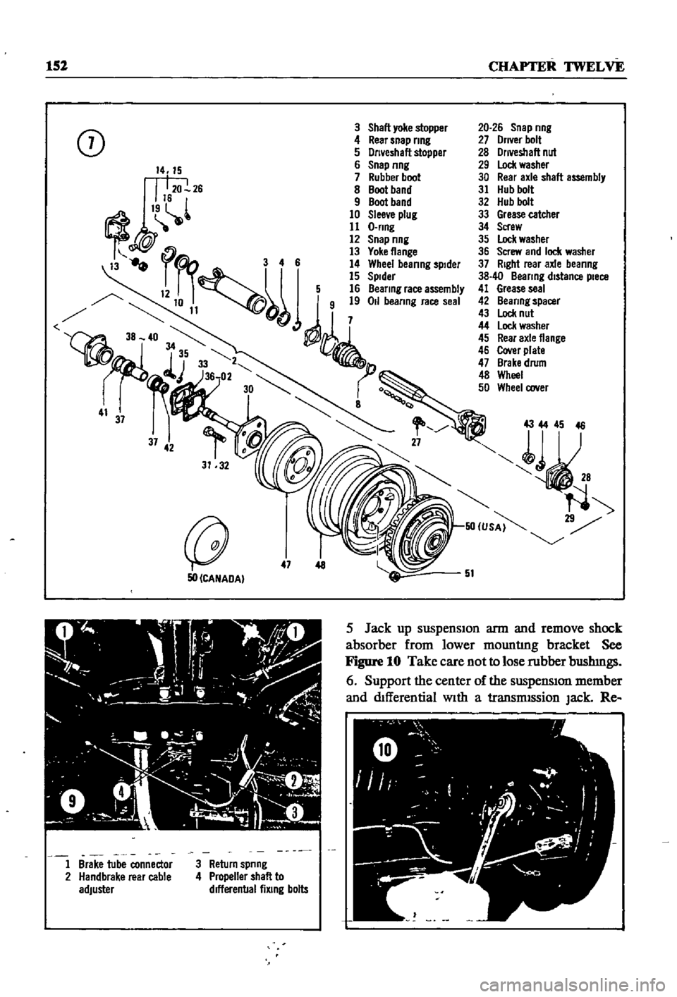
Figure
7
and
Figure
8
page
153
are
ex
ploded
dIagrams
of
the
sedan
rear
axle
and
suspensIOn
The
fully
independent
rear
suspen
SIon
IS
a
semI
traIlIng
arm
deSIgn
With
a
sus
penSIOn
member
suspensIOn
arms
coIl
spnngs
and
hydraulIc
shock
absorbers
The
wheel
bearings
are
lIfetime
lubncated
Rear
Axle
and
Suspension
Removal
Sedan
1
Jack
up
the
rear
of
the
veh1cle
and
support
It
on
stands
2
Remove
wheels
3
Refer
to
Figure
9
and
dtsconnect
handbrake
lInkage
and
rerum
sprmg
Remove
tall
pIpe
and
muffler
4
DISconnect
brake
hose
from
brake
tube
Re
move
four
bolts
holdmg
dnve
shaft
to
dIf
ferential
Lower
dnve
shaft
gently
to
ground
Page 157 of 252
152
CHAPTER
TWELVE
3
Shall
yoke
stopper
0
4
Rear
snap
nng
J
5
Dn
eshall
stopper
6
Snap
nng
7
Rubber
boot
8
Boot
band
9
Boot
band
10
Slee
e
plug
11
O
nng
12
Snap
nng
13
Yoke
flange
3
4
6
14
Whee
beanng
spIder
15
Spider
12
5
16
Beanng
race
assembly
j
50
CANADA
47
AtO
C
J
ty
9
1
Y
4
i
l
A
I
ii
1
o
l
J
Il
h
o
20
J
I
1
Brake
tube
connector
2
Handbrake
rear
cable
adjuster
3
Return
spnng
4
Propeller
shall
to
dlfferenballixlng
bolts
20
26
Snap
nng
27
Dn
er
bolt
28
Onveshall
nut
29
Lock
washer
30
Rear
axle
shall
assembly
31
Hub
bolt
32
Hub
bolt
33
Grease
catcher
34
Screw
35
Lock
washer
36
Screw
and
Ioc
l
washer
37
Right
rear
axle
beanng
38
40
Beanng
distance
piece
41
Grease
seal
42
Beanng
spacer
43
Lock
nut
44
lock
washer
45
Rear
axle
flange
46
Cover
plate
47
Brake
drum
48
Wheel
50
Wheel
oover
43
44
45
46
51
5
Jack
up
suspenSIon
arm
and
remove
shock
absorber
from
lower
mountlng
bracket
See
Figure
10
Take
care
not
to
lose
rubber
bushmgs
6
Support
the
center
of
the
suspensIon
member
and
dIfferential
With
a
transmISsion
Jack
Re
Page 160 of 252
DIFFERENTIAL
REAR
AXLE
AND
REAR
SUSPENSION
155
i
I
I
I
REAR
SUSPENSION
ARM
SEDAN
Rear
Suspension
Arm
Removal
Sedan
1
Jack
up
the
rear
of
the
vehIcle
and
support
It
on
stands
2
Remove
wheel
and
brake
drum
3
DIsconnect
dnve
shaft
from
axle
shaft
4
Remove
handbrake
cable
from
lever
attached
to
wheel
cylInder
5
Plug
brake
tube
to
prevent
loss
of
brake
flwd
6
Remove
wheel
beanng
lock
nut
rear
axle
shaft
wheel
beanngs
and
OIl
seal
Remove
rear
brake
assembly
from
suspensIOn
arm
7
Place
Jack
under
suspenSIon
arm
remove
shock
absorber
from
lower
bracket
lower
Jack
gradually
remove
coll
spnng
spnng
seat
and
bumper
assembly
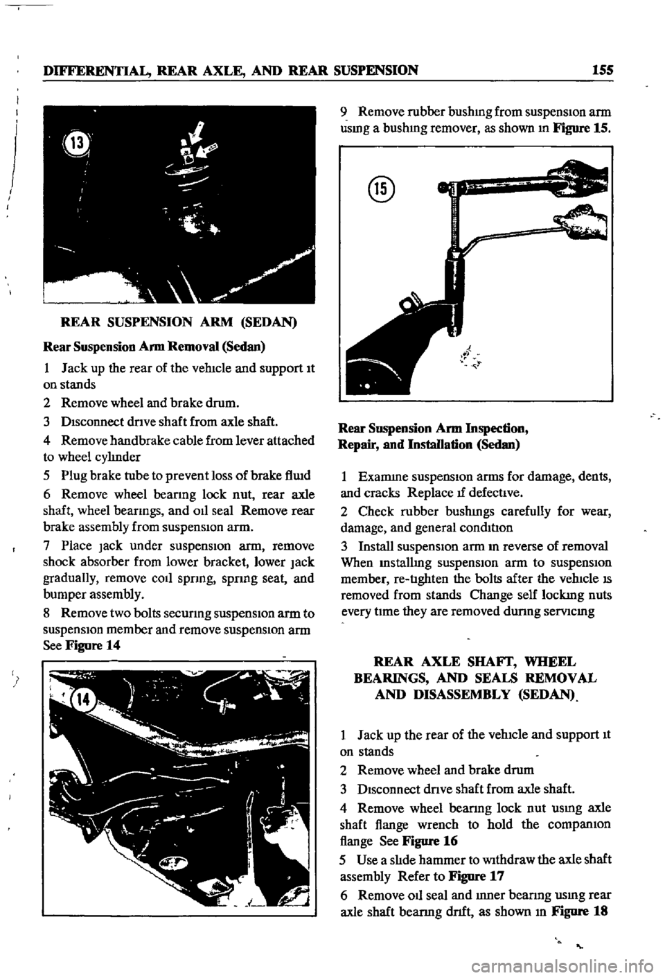
8
Remove
two
bolts
secunng
suspensIOn
arm
to
suspensIOn
member
and
remove
suspensIOn
arm
See
Figure
14
9
Remove
rubber
bushmg
from
suspensIon
arm
usmg
a
bushmg
remover
as
shown
In
Figure
15
@
Rear
SllSpension
Arm
Inspection
Repair
and
Installation
Sedan
1
Examme
suspensIOn
arms
for
damage
dents
and
cracks
Replace
tf
defectIve
2
Check
rubber
bushmgs
carefully
for
wear
damage
and
general
condItIon
3
Install
suspensIOn
arm
m
reverse
of
removal
When
Installmg
suspensIOn
arm
to
suspensIOn
member
re
tIghten
the
bolts
after
the
vehIcle
IS
removed
from
stands
Change
self
lockmg
nuts
every
tIme
they
are
removed
dunng
semcmg
REAR
AXLE
SHAFf
WHEEL
BEARINGS
AND
SEALS
REMOVAL
AND
DISASSEMBLY
SEDAN
1
Jack
up
the
rear
of
the
vehIcle
and
support
It
on
stands
2
Remove
wheel
and
brake
drum
3
DIsconnect
dnve
shaft
from
axle
shaft
4
Remove
wheel
bearmg
lock
nut
usmg
axle
shaft
flange
wrench
to
hold
the
companIOn
flange
See
Figure
16
5
Use
a
slIde
hammer
to
Withdraw
the
axle
shaft
assembly
Refer
to
Figure
17
6
Remove
011
seal
and
Inner
bearmg
usmg
rear
axle
shaft
bearmg
dnft
as
shown
In
Figure
18
Page 162 of 252

DIFFERENTIAL
REAR
AXLE
AND
REAR
SUSPENSION
157
DIFFERENTIAL
WAGON
The
dIfferentIal
carner
is
made
of
alumInum
alloy
and
uses
a
hypoid
bevel
gear
Proper
lubri
catIon
IS
essentIal
Check
and
replemsh
the
lub
rIcant
every
3
000
mIles
Dram
and
refill
every
30
000
mlles
Figure
20
IS
an
exploded
dIagram
of
the
differential
used
in
the
wagon
Difterential
Removal
Wagon
1
Jack
up
the
rear
wheels
and
support
vehicle
with
stands
l
2
DIsconnect
drIve
pmlon
companion
flange
to
yoke
connectIon
3
Remove
rear
wheel
axles
as
descnbed
later
m
thIS
chapter
4
Remove
dtfferentIal
from
vehIcle
Difterential
Inspection
Wagon
The
followmg
Inspection
can
be
done
Without
dISassembly
of
the
differentIal
Perform
the
fol
lOWIng
mspectIon
and
If
abnormalitIes
or
dam
age
eXISts
refer
further
service
and
repair
to
YOI
f
dealer
1
Check
the
tooth
contact
pattern
with
lead
oXIde
at
two
or
three
pomts
after
remoVIng
rear
cover
Refer
to
FIgure
5
for
correct
contact
pat
tern
If
the
pattern
IS
not
correct
dIsassembly
and
adjustment
of
the
dtfferentIalIS
reqUIred
2
Measure
backlash
between
dnve
gear
and
pInIOn
WIth
a
dIal
mdlcator
Backlash
should
be
00059
to
00079
in
0
15
to
0
20mm
3
Rotate
the
gears
and
lIsten
for
SIgnS
of
bear
Ing
nOIse
DefectIve
beanngs
should
be
replaced
by
a
dealer
4
Inspect
gear
teeth
for
signs
of
damage
or
cracks
r
Difterential
Installation
Wagon
Install
the
dIfferentIal
by
reversing
the
pro
cedures
used
for
removal
2
Olfferenllal
case
16
Pmlon
10Ckmg
pm
28
42
AdjusllRg
washer
t
3
Beanng
stud
17
Dlflerenbal
Side
beanng
43
47
Adjusting
shim
4
Plem
washer
18
22
Adjusting
shim
53
Oil
seal
5
Locking
nut
23
Rear
plRlOn
gear
54
Range
assembly
6
Lockmg
nut
24
Front
plRlOn
beanng
55
Nut
7
PIRlOn
gear
set
25
27
Spacer
56
Wesher
Iff
8
Hex
bolt
9
Bolt
locking
strap
7
10
Case
@
11
Side
gear
12
PmlOn
mete
is
Thrust
washer
13
14
Thrust
washer
10
15
PIRlOn
shaft
23
43
47
2S
27
7
J
I
18
22
17
l
24
S3
S6
S4
55
Page 164 of 252
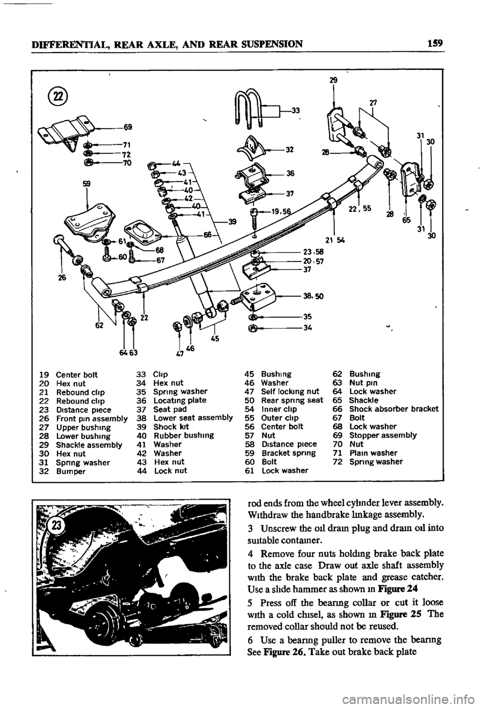
DIFFERENTIAL
REAR
AXLE
AND
REAR
SUSPENSION
159
@
8
69
71
72
70
26
29
32
19
5
T1
31
30
21
4
23
58
20
57
37
45
6463
19
Center
bolt
33
Clip
45
Bushmg
62
Bushing
20
Hex
nut
34
Hex
nut
46
Washer
63
Nut
pin
21
Rebound
clip
35
Spring
washer
47
Self
locking
nut
64
Lock
washer
22
Rebound
clip
36
Locatmg
plate
50
Rear
spring
seat
65
Shackle
23
DIstance
piece
37
Seat
pad
54
Inner
clip
66
Shock
absorber
bracket
26
Front
pm
assembly
38
Lower
seat
assembly
55
Outer
clip
67
Bolt
27
Upper
bushing
39
Shock
kit
56
Center
bolt
68
Lock
washer
28
Lower
bushing
40
Rubber
bushing
57
Nut
69
Stopper
assembly
29
Shackle
assembly
41
Washer
58
Distance
piece
70
Nut
30
Hex
nut
42
Washer
59
Bracket
spring
71
Plam
washer
31
Spnng
washer
43
Hex
nut
60
Bolt
72
Spring
washer
32
Bumper
44
Lock
nut
61
Lock
washer
rod
ends
from
the
wheel
cylInder
lever
assembly
WIthdraw
the
handbrake
lInkage
assembly
3
Unscrew
the
011
dram
plug
and
draIn
011
into
sUItable
contamer
4
Remove
four
nuts
holdmg
brake
back
plate
to
the
axle
case
Draw
out
axle
shaft
assembly
WIth
the
brake
back
plate
and
grease
catcher
Use
a
slIde
hammer
as
shown
In
Figure
24
5
Press
off
the
beanng
collar
or
cut
it
loose
WIth
a
cold
chIsel
as
shown
m
Figure
25
The
removed
collar
should
not
be
reused
6
Use
a
beanng
puller
to
remove
the
bearmg
See
Figure
26
Take
out
brake
back
plate
Page 165 of 252

160
CHAPTER
TWELVE
@
@
@
I
F
7
Remove
ten
nuts
holdmg
the
drlIerentIal
assembly
to
the
axle
case
and
withdraw
the
differential
aSsembly
Rear
Axle
Inspection
Assembly
nnd
Installation
Wagon
1
Check
the
axle
shafts
for
straighmess
cracks
damage
wear
and
chstortion
Replace
1f
de
fectIve
Do
not
attempt
to
heat
axle
to
straJghten
I
it
as
thiS
wlll
weaken
the
axle
and
could
lead
to
more
senous
trouble
2
Clean
all
parts
thoroughly
With
solvent
3
Check
011
seal
hp
for
damage
Replace
as
requrred
4
Check
the
beanngs
for
damage
and
replace
1f
defective
5
Assemble
the
rear
axle
urnt
in
the
reverse
of
disassembly
6
Use
a
new
gasket
between
axle
cases
and
drlIerentIal
7
The
gear
carner
fixmg
nuts
must
be
torqued
m
a
diagonal
pattern
to
prevent
011
leaks
Tighten
to
145
to
159ft
lb
20
to
22
kg
m
8
Install
the
grease
catcher
beanng
spacer
bearmg
and
new
bearing
collar
on
the
axle
shaft
The
beanng
collar
must
be
fitted
using
an
arbor
press
and
4
to
5
tons
of
force
Make
cectam
to
pack
the
wheel
beanng
With
grease
and
msert
the
wheel
beanng
With
the
seal
Side
toward
the
wheel
9
If
the
011
seal
has
been
replaced
take
care
not
to
damage
it
when
mstallmg
the
axle
shaft
assembly
As
a
matter
of
good
practice
replace
the
011
seal
whenever
the
axle
is
disassembled
10
Refer
to
Figure
27
and
grease
the
mdicated
areas
Torque
all
bolts
as
speCified
11
Adjust
the
aXial
end
play
between
the
wheel
beanng
and
the
recess
in
the
axle
tube
with
adjusting
shims
The
end
play
should
be
00118
to
00197
m
03
to
O
5mm
Check
end
play
with
a
dial
gauge
as
shown
in
Figure
28