1968 DATSUN 510 differential
[x] Cancel search: differentialPage 166 of 252
DIFFERENTIAL
REAR
AXLE
AND
REAR
SUSPENSION
161
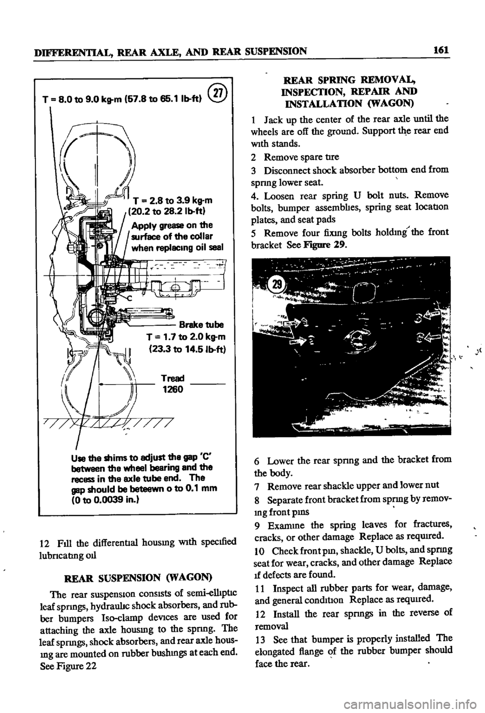
T
8
0
to
9
0
kg
m
57
8
to
65
11b
ft
@
T
2
8
to
3
9
kg
m
20
2
to
28
2
Ib
ft
Apply
grease
on
the
surface
of
the
collar
when
replacing
oil
seal
Brake
tube
T
1
7
to
2
0
kg
m
23
3
to
14
5
Ib
ft
Tread
1260
Use
the
shims
to
adjust
the
gap
C
between
the
wheel
bearing
and
the
recess
in
the
axle
tube
end
The
gap
should
be
beteewn
0
to
0
1
mm
0
to
0
0039
in
12
Fill
the
differentIal
housmg
With
specmed
lubncabng
011
REAR
SUSPENSION
WAGON
The
rear
suspensiOn
consists
of
semi
elhpnc
leaf
spnngs
hydraulJc
shock
absorbers
and
rub
ber
bumpers
Iso
clamp
deVices
are
used
for
attaching
the
axle
housmg
to
the
spnng
The
leaf
spnngs
shock
absorbers
and
rear
axle
hous
mg
are
mounted
on
rubber
bushmgs
at
each
end
See
Figure
22
REAR
SPRING
REMOVAL
INSPECTION
REPAIR
AND
INSTALLATION
WAGON
1
Jack
up
the
center
of
the
rear
axle
until
the
wheels
are
off
the
ground
Support
th
e
rear
end
With
stands
2
Remove
spare
tIre
3
Disconnect
shock
absorber
bottom
end
from
spnng
lower
seat
4
Loosen
rear
spring
U
bolt
nuts
Remove
bolts
bumper
assembhes
spring
seat
location
plates
and
seat
pads
5
Remove
four
fiXing
bolts
holdmg
the
front
bracket
See
Figure
29
l
6
Lower
the
rear
spnng
and
the
bracket
from
the
body
7
Remove
rear
shackle
upper
and
lower
nut
8
Separate
front
bracket
from
spnng
by
remov
mg
front
pms
9
Exanune
the
spring
leaves
for
fractIires
cracks
or
other
damage
Replace
as
reqwred
10
Check
front
pm
shackle
U
bolts
and
spnng
seat
for
wear
cracks
and
other
damage
Replace
1f
defects
are
found
11
Inspect
all
rubber
parts
for
wear
damage
and
general
condil1on
Replace
as
reqUired
12
Install
the
rear
spnngs
in
the
reverse
of
removal
13
See
that
bumper
is
properly
installed
The
elongated
flange
of
the
rubber
bumper
should
face
the
rear
Page 167 of 252

162
CHAPTER
TWELVE
14
Coat
the
front
bracket
pm
and
bushmg
and
shackle
pm
and
bushing
With
a
soap
solution
pnor
to
assembly
15
The
front
pm
secunng
nut
and
shock
ab
sorber
lower
end
securmg
nut
should
be
re
tightened
after
the
vehicle
is
sittmg
on
the
ground
16
Make
certaJn
the
shackle
bushmg
flange
is
clamped
evenly
on
both
Sides
SHOCK
ABSORBER
REMOVAL
INSPECTION
AND
INSTALLATION
WAGON
1
Jack
up
the
center
of
the
rear
axle
and
sup
port
th
e
axle
housmg
With
stands
2
Reinove
the
lower
end
of
the
rear
shock
absorber
from
spring
seat
3
Loosen
the
four
bolts
secunng
the
upper
bracket
to
body
Remove
shock
absorber
and
upper
bracket
4
Check
shock
absorber
for
leaks
and
cracks
Check
the
shaft
for
straighmess
Replace
1f
defective
5
Inspect
rubber
bushmgs
for
damage
cracks
and
general
condition
Replace
1f
defective
6
Install
the
shock
absorber
by
reversing
the
procedure
used
durmg
removal
DIFFERENTIAL
pICK
UP
The
dlfferenl1al
carner
IS
made
up
of
alum
mum
alloy
and
uses
a
hyp01d
bevel
gear
Proper
lubncatIon
IS
essenl1al
Check
and
replemsh
the
lubncant
every
3
000
mlles
Drain
and
refill
every
30
000
inlles
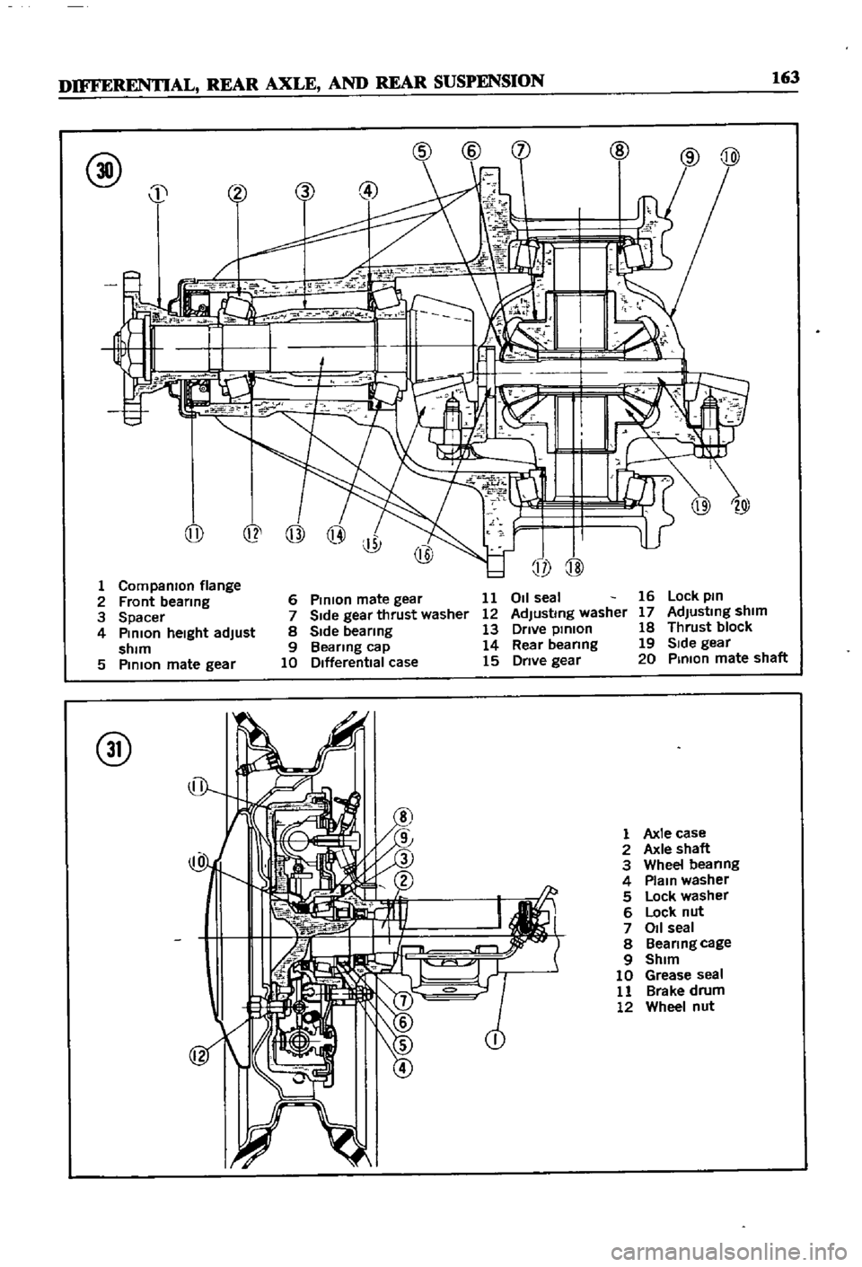
Figure
30
IS
a
cross
sectional
View
of
the
pick
up
dIfferential
Difterential
Removal
Pick
up
1
Jack
up
the
rear
wheels
and
support
vehicle
With
stands
2
DIsconnect
dnve
pmlOn
companlOn
flange
to
yoke
connectIon
3
Remove
rear
axles
as
descnbed
later
m
thIS
chapter
4
Remove
dlfferenl1al
gear
assembly
Difterential
Inspection
Pick
up
The
followmg
mspection
can
be
done
Without
disassembly
of
the
d1fferenl1al
If
abnormahties
or
damage
eXiSts
refer
further
serVice
and
reparr
to
your
dealer
1
Check
the
tooth
contact
pattern
WIth
lead
OXide
at
two
or
three
pomts
after
remoVlDg
rear
cover
Refer
to
FIgure
5
for
correct
contact
pattern
If
the
pattern
IS
faulty
disassembly
and
adJustment
of
the
dIfIerentialIs
required
2
Measure
backlash
between
dnve
gear
and
pmlOn
With
a
dial
mdlcator
Backlash
should
be
00051
to
0
0071
m
013
to
0
18mm
3
Rotate
the
gears
and
lISten
for
SignS
of
bear
mg
noise
4
Inspect
gear
teeth
for
SIgnS
of
damage
or
cracks
Difterential
Installation
Pick
up
Install
the
differential
by
reversmg
the
pro
cedures
used
dunng
removal
REAR
AXLE
AND
SUSPENSION
pICK
UP
The
rear
axle
IS
of
the
semi
floatIng
type
The
rear
wheels
use
tapered
roller
beanngs
Figure
31
IS
a
cross
sectional
view
of
the
rear
axle
REAR
SUSPENSION
TORQUE
TIGHTENING
SPECIFICATIONS
WAGON
Shock
absorber
upper
bracket
to
body
bolts
Shock
absorber
to
upper
bracket
lock
nuts
Shock
absorber
to
lower
bracket
lock
nuts
Rear
spnng
U
bolt
nuts
Shackle
nuts
Front
pm
nuts
Front
bracket
flxmg
nuts
Brake
dISC
to
rear
housmg
bolts
DifferentIal
carner
to
axle
housmg
bolt
Dnve
shaft
flange
nuts
11
to
18
ft
Ib
1
5
to
2
5
kg
m
12
to
16
ft
db
17
to
2
2
kg
m
25
to
33
ft
Ib
35
to
45
kg
m
43
to
47
ft
Ib
60
to
6
5
kg
m
32
to
36
ft
Ib
45
to
50
kg
m
32
to
36
ft
Ib
45
to
5
0
kg
m
13
to
17
ft
Ib
18
to
23
kg
m
20
to
28
ft
Ib
28
to
3
9
kg
m
14
to
16
ft
Ib
20
to
2
2
kg
m
20
to
28
ft
Ib
28
to
3
9
kg
m
Page 168 of 252
DIFFERENTIAL
REAR
AXLE
AND
REAR
SUSPENSION
163
@
j
@
@
@
1
Companron
flange
2
Front
bearmg
3
Spacer
4
Pmlon
heIght
adjust
shim
5
PmlOn
mate
gear
@
6
Pmlon
mate
gear
11
7
Side
gear
thrust
washer
12
8
Side
bearmg
13
9
Bearing
cap
14
10
Differential
case
15
011
seal
Adjusting
washer
Drive
pmlon
Rear
beanng
Drive
gear
16
Lock
pm
17
AdJustmg
shim
18
Thrust
block
19
SIde
gear
20
Pmlon
mate
shaft
@
1
Axle
case
2
Axle
shaft
3
Wheel
beanng
4
Plam
washer
5
Lock
washer
6
Lock
nut
7
011
seal
8
Beanngcage
9
Shim
10
Grease
seal
11
Brake
drum
12
Wheel
nut
Page 170 of 252
DIFFERENTIAL
REAR
AXLE
AND
REAR
SUSPENSION
165
2
Check
wheel
bearmgs
for
damage
or
noise
Replace
them
If
defective
3
Be
sure
to
use
new
011
seals
and
lockwashers
4
FIt
beanng
cup
and
grease
seal
to
cage
Tap
WIth
a
brass
hammer
while
fittIng
FIll
grease
seal
IIp
With
wheel
beanng
grease
after
fittmg
5
Install
brake
diSC
and
beanng
cage
on
axle
Fit
bearmg
cone
With
brass
bar
6
Tighten
lock
nut
Place
faced
Side
of
nut
to
washer
SIde
so
that
washer
IS
not
damaged
Torque
lock
nut
to
10S
to
145
ft
lb
15
to
20
kg
m
7
Match
washer
IIp
With
groove
m
nut
tIghten
nut
and
bend
washer
carefully
to
prevent
hp
damage
S
Use
a
brass
bar
to
fit
011
seal
to
tube
end
When
fitted
apply
grease
to
the
hp
Be
careful
not
to
deform
seal
or
damage
hp
9
Completely
fill
bearmg
With
grease
10
Install
shaft
AdJust
aXial
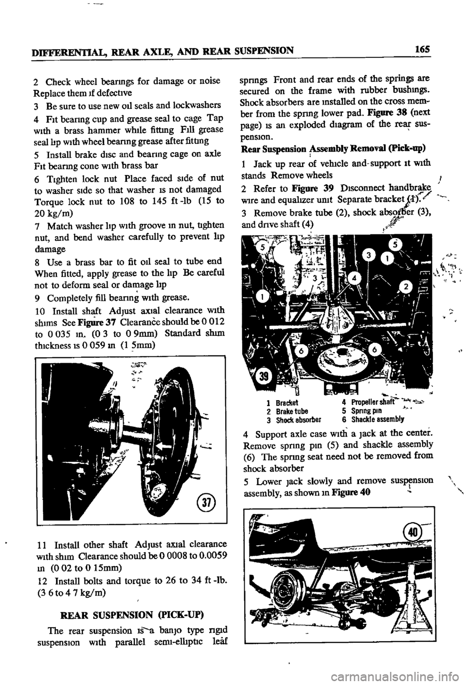
clearance
With
shIms
See
Figure
37
Clearance
should
be
0
012
to
0
035
m
0
3
to
09mm
Standard
shIm
thickness
IS
0
059
m
1
5mm
@
11
Install
other
shaft
AdJust
aXlal
clearance
With
shIm
Clearance
should
be
0
OOOS
to
0
0059
m
002
to
0
15mm
12
Install
bolts
and
torque
to
26
to
34
ft
lb
3
6
to
4
7
kg
m
REAR
SUSPENSION
PICK
UP
The
rear
suspension
IS
a
banJO
type
ngId
suspensIOn
With
parallel
semI
elhpnc
leaf
spnngs
Front
and
rear
ends
of
the
springs
are
secured
on
the
frame
with
rubber
bushmgs
Shock
absorbers
are
mstalled
on
the
cross
mem
ber
from
the
spnng
lower
pad
Figure
38
next
page
IS
an
exploded
dIagram
of
the
rear
sus
pensIOn
Rear
Suspension
Assembly
Removal
Pick
up
1
Jack
up
rear
of
vehicle
and
support
It
With
stands
Remove
wheels
2
Refer
to
Figure
39
DIsconnect
handbrake
Wire
and
equalIZer
unit
Separate
bracketJt
r
3
Remove
brake
tube
2
shock
absorller
3
and
dnve
shaft
4
r
r
0
it
1
Bracket
4
Propeller
shaft
2
Brake
tube
5
Spnng
pm
3
Shock
absorber
6
Shackle
assembly
4
Support
axle
case
With
a
Jack
at
the
center
Remove
spnng
pm
5
aJId
shackle
assembly
6
The
sprmg
seat
need
not
be
removed
from
shock
absorber
5
Lower
Jack
slowly
and
remove
susp
nslOn
assembly
as
shown
m
Figure
40
Page 172 of 252

DIFFERENTIAL
REAR
AXLE
AND
REAR
SUSPENSION
167
REAR
SUSPENSION
pICK
UP
Rear
Suspension
Inspection
nnd
Repair
Pick
up
1
Check
spnngs
for
cracks
breaks
and
general
conditIon
Replace
as
reqwred
If
a
spnng
on
one
Side
IS
replaced
also
replace
the
other
one
2
Check
U
bolts
for
bends
stripped
threads
and
general
conditIon
Replace
as
reqUIred
3
Check
rubber
bumpers
and
bushings
for
cracks
wear
and
general
condll1on
Replace
if
defecl1ve
4
Check
shock
absorbers
for
leaks
or
other
damage
Replace
as
required
Rear
Suspension
Installation
Pick
up
1
Replace
the
rear
suspension
components
m
the
reverse
order
of
removal
2
When
msta11mg
rubber
bushmgs
coat
them
hghtly
With
a
soap
solution
3
Torque
parts
as
follows
Shackle
Pin
Spnng
Pm
U
Bolt
Secunng
Nut
Shock
Absorber
Upper
Nut
Shock
Absorber
Lower
Nut
Dnve
Shalt
Secunng
Bolt
83
to
94
It
Ib
11
5
to
13
kg
m
83
to
94
It
Ib
115
to
13
kg
m
61
to
72
ItAb
85
to
10
kg
m
26
to
31
It
Ib
36
t04
3
kg
m
10
to
12
ft
Ib
1
4
to
1
6
kg
m
18
to
22
ft
Ib
25
to
30
kg
m
NOTE
Retighten
bolts
and
nuts
that
hold
bushmgs
after
vehicle
has
been
removed
from
Jack
and
stands
Page 242 of 252
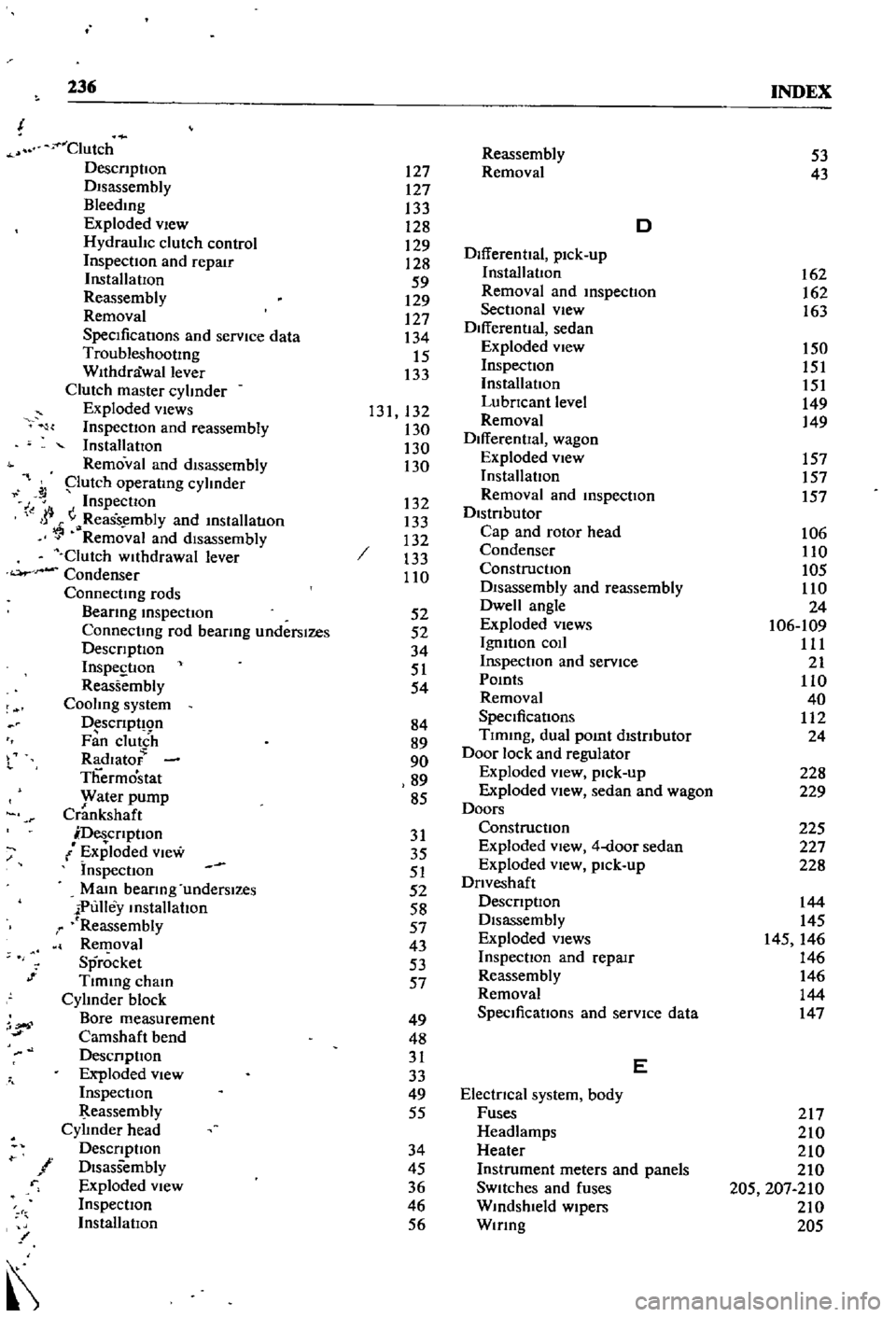
236
INDEX
Clutch
DescnptIon
DIsassembly
Bleedmg
Exploded
vIew
Hydraulic
clutch
control
InspectIOn
and
repair
InstallatIOn
Reassembly
Removal
SpecificatIons
and
service
data
TroubleshootIng
Withdrawal
lever
Clutch
master
cylinder
Exploded
views
InspectIon
and
reassembly
InstallatIOn
Removal
and
disassembly
putch
operatmg
cylinder
J
Inspection
I
jj
ReaSs
mbly
and
mslallatlOn
Removal
and
disassembly
Clutch
wllhdrawal
lever
Condenser
Connectmg
rods
Beanng
mspectIon
Connectmg
rod
bearmg
underslzes
DescrIptIOn
InspestIon
Reassembly
Cooling
system
D
scrIpt
Qn
Fan
clutch
Radlato
Thermostat
yvater
pump
Crankshaft
DescrIptIon
Exploded
View
Inspection
Mam
bearIng
underslzes
iPulley
mstallahon
r
Reassembly
Removal
Sprocket
Tlmmg
cham
Cylinder
block
Bore
measurement
Camshaft
bend
DesCrIpllOn
Exploded
view
InspectIOn
eassembly
Cylinder
head
DescrIptIon
f
DIsassembly
r
Exploded
View
InspectIOn
InstallatIOn
l
or
1
Reassembly
127
Removal
127
133
128
D
129
DifferentIal
pick
up
128
59
InstallatIon
129
Removal
and
mspecllOn
127
SectIOnal
view
134
Differential
sedan
15
Exploded
view
133
Inspection
InstallatIOn
131
132
LubrIcant
level
130
Removal
130
DifferentIal
wagon
130
Exploded
view
InstallatIon
132
Removal
and
mspecllon
133
DistrIbutor
132
Cap
and
rotor
head
133
Condenser
110
ConstructIon
DIsassembly
and
reassembly
52
Dwell
angle
52
Exploded
Views
34
IgmtIon
coIl
51
Inspection
and
service
54
Pomts
Removal
84
SpeCificatIons
89
Tlmmg
dual
pomt
distrIbutor
90
Door
lock
and
regulator
89
Exploded
view
pick
up
85
Exploded
View
sedan
and
wagon
Doors
31
Construction
35
Exploded
view
4
door
sedan
51
Exploded
vIew
pick
up
52
DrIveshaft
58
DescrIptIOn
57
Disassembly
43
Exploded
Views
53
InspectIon
and
repaIr
57
Reassembly
Removal
49
SpeCificatIons
and
service
data
48
31
E
33
49
ElectrIcal
system
body
55
Fuses
Headlamps
34
Heater
45
Instrument
meters
and
panels
36
SWitches
and
fuses
46
Wmdshleld
wipers
56
Wmng
53
43
162
162
163
150
151
151
149
149
157
157
157
106
110
105
110
24
106
109
111
21
110
40
112
24
228
229
225
227
228
144
145
145
146
146
146
144
147
217
210
210
210
205
207
210
210
205
Page 252 of 252
r
t
i
f
If
t
I
DAnUN
SE
1
5
10
AN
l
@
0
i1
rtr
JM
OIi
l
jj
I
I
if
J
I
f
lJ
I
I
f
I
I
tflr
f1
h
f
I
v
L
7
I
l1It
l
I
fIr
t
I
r
II
to
E
m
PAIIt
I
lANI
X
I
I
PICK
UP
1968
1972
t
t
I
0
l
1
j
f
r
t
g
I
I
0
r
r
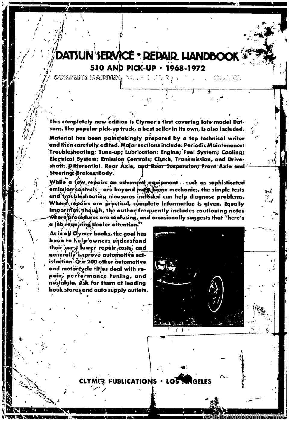
This
completely
new
edition
is
Clymer
s
first
covering
late
model
Dat
ouns
The
popular
pick
up
truck
a
best
seller
in
its
own
is
also
included
Material
has
been
pai
stakingly
prepared
by
a
top
technical
writer
and
tlien
carefully
edited
Major
sections
include
Periodic
Maintenance
Trouble
hooting
Tune
up
Lubrication
Engine
Fuel
System
Cooling
Ele
rical
System
Emissio
ontrols
Clytch
Transmission
and
Drive
shaft
Differential
Rear
Axle
Steering
rakes
1
Body
Wbiie
a
f
re
airs
on
advan
lMI
eauipment
such
as
sophisticated
1
II
emissi
ontruls
are
beyond
e
mechanics
the
simple
tests
I
f
l
1
1
and
t
ubl
shooting
measures
ndtided
can
help
diagnose
problems
Wher
r
lrs
are
practical
cr
mplete
informatfon
is
given
Equally
im
t
nt
ho
gh
thi
autho
frequently
includes
cautioning
gotes
1
f
I
where
proCeduljes
are
confusing
and
occasionally
suggests
that
here
s
b
I
t
1
t
I
a
10
1requ
ring
uea
er
attentloru
Ii
l
I
As
in
ail
C
ymer
books
the
goal
has
j
I
I
1
be
n
to
kelp
owners
understand
th
ir
far
owpr
repair
costs
and
generaUi
i
lnprove
automotive
sat
isfadion
O
Jr
200
other
utomotive
and
motcwc
y
c1e
itles
deal
with
re
pairl
performance
tuning
and
nostalgia
Ask
for
them
at
leading
J
book
stores
and
auto
supply
outlets
I
CLY
PUBLI
ATll
LO
MGELES
1
6
r
I
l
t