1968 DATSUN 510 door lock
[x] Cancel search: door lockPage 5 of 252
CHAPTER
TWELVE
DIFFERENTIAL
REAR
AXLE
AND
REAR
SUSPENSION
149
DIfferentIal
Rear
axle
and
suspension
Codspnng
Shock
absorber
Rear
suspensIOn
arm
Rear
axle
shaft
Wheel
beanngs
Seals
Rear
spnng
Axle
case
SpecificatIons
CHAPTER
THIRTEEN
FRONT
AXLE
FRONT
SUSPENSION
AND
STEERING
168
Wheel
hub
and
bearmg
StabilIzer
TenSion
rod
Spnng
and
strut
assembly
Transverse
lInk
Lower
ball
Jomt
Front
suspension
adjustment
Wheel
alignment
Posture
adJustment
Steenng
system
SpeCificatIons
CHAPTER
FOURTEEN
BRAKES
187
Brake
pedal
Master
cylInder
Front
diSC
brakes
Rear
brakes
Front
drum
brakes
Wheel
cylInders
Brake
system
bleedIng
Handbrake
Service
data
and
speCificatIons
CHAPTER
FIFTEEN
BODY
ELECTRICAL
SYSTEM
Wmng
SWitches
and
fuses
Instrument
meters
and
panels
Heater
205
Wmdshleld
wipers
Wmdslueld
washers
Headlamps
WIrIng
diagrams
CHAPTER
SIXTEEN
BODY
223
Front
body
trIm
Bumpers
Hood
lock
control
Doors
Door
locks
and
regulators
Trunk
lId
and
rear
bumper
Seats
Tad
gate
INDEX
235
I
Page 6 of 252
CHAPTER
ONE
GENERAL
INFORMATION
This
manual
provides
maintenance
informa
tIon
on
the
Datsun
510
Series
and
521
Series
of
vehlcles
The
510
Series
includes
the
two
door
sedan
four
door
sedan
and
station
wagon
The
521
Senes
IS
the
pIck
up
truck
Coverage
is
from
1968
through
1972
models
All
models
use
the
L16
engme
a
96
horse
power
four
cylmder
overhead
camshaft
design
The
510
has
a
fully
synchronized
four
speed
manual
or
three
speed
automatic
transmisSIon
The
521
has
a
four
speed
manual
transmission
only
In
1972
horsepower
ratIng
was
lowered
to
92
horsepower
due
to
changes
m
emission
control
device
requirements
Figure
1
is
an
over
all
view
of
the
four
door
sedan
Figure
2
shows
the
station
wagon
and
Figure
3
illustrates
the
pick
up
truck
Over
the
years
the
510
and
521
series
have
remained
essentIally
the
same
with
the
excep
tion
of
changes
to
the
emISsion
control
systems
and
overall
body
stylmg
In
this
manual
every
effort
has
been
made
to
pinpoint
significant
c
if
ferences
between
model
years
The
use
of
SpecIal
tools
and
test
equipment
has
been
avoided
wherever
possible
When
necessary
special
tools
and
test
equipment
are
illustrated
either
in
actual
use
or
alone
A
well
equipped
mecharuc
may
find
he
can
substitute
similar
tools
or
make
his
own
to
fulfill
a
e
Ii
ment
Recommendations
are
occasionally
made
to
refer
servIce
or
mamtenance
to
a
Datsun
dealer
or
a
SpecIaliSt
in
a
specIfied
field
In
these
cases
work
WIll
probably
be
done
more
qUlckly
and
economIcally
than
if
the
mecharuc
performs
them
himself
MODEL
IDENTIFICATION
Body
Number
Plate
The
body
number
IS
stamped
on
the
fire
wall
in
the
engine
compartment
The
numbers
give
the
chasSIS
model
and
serial
number
Model
Identification
Plate
The
model
Identification
plate
Figure
4
is
mounted
WIthin
the
engine
compartment
TIns
plate
gIves
engine
number
and
veh1cle
number
Engine
Identification
The
engine
identrlicatlon
marking
is
stamped
on
the
right
hand
SIde
of
the
cylinder
block
just
below
the
third
and
fourth
sp8l
k
plugs
Model
Identification
Numbel
ll
The
following
numbers
have
been
assigned
to
the
510
and
52
I
Series
vehicles
oj
Page 214 of 252
44
y
l
l
42
43
r
48
cr
23
41
f
Jj
it
d
F
1L
f7
IF
f
0
l
Q
U
lJ
37
1
2S
26
38
A
3S
36
G
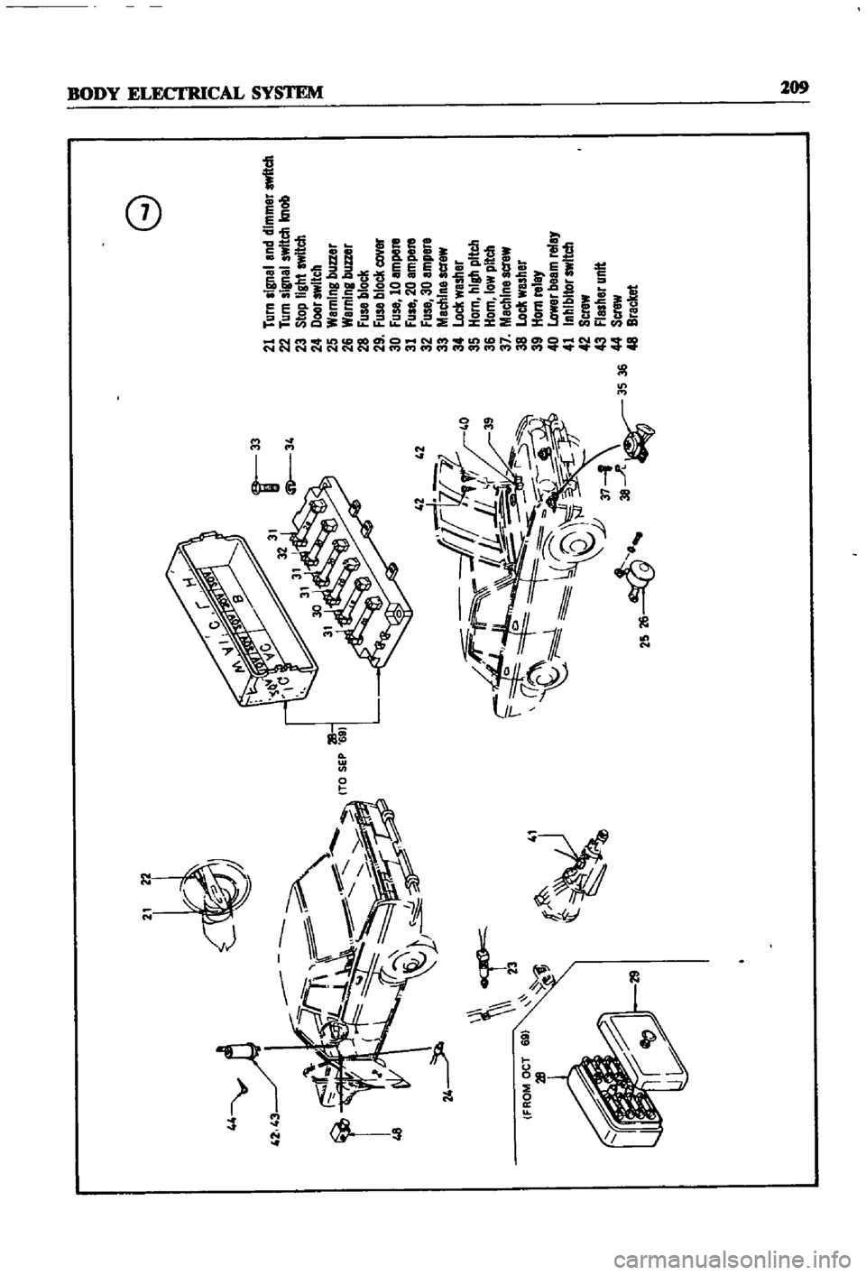
21
Turn
signal
and
dimmer
switch
22
Turn
signal
switch
knob
23
Stop
light
switch
24
Door
switch
25
WarnIng
buzzer
26
Warning
buzzer
28
Fuse
block
29
Fuse
block
cover
30
Fuse
10
ampere
31
Fuse
20
ampere
32
Fuse
30
ampere
33
Machlnescrew
34
Lock
washer
35
Horn
hIgh
pitch
36
Horn
low
pitch
37
Machine
acrew
38
Lock
washer
39
Horn
relay
40
Lower
beem
relay
41
Inhibitor
switch
42
Screw
43
Flasher
unit
44
Screw
48
Bracket
o
i
Page 230 of 252
CHAPTER
SIXTEEN
ThIS
chapter
provides
infOrnl8tion
and
pro
cedures
for
removal
adJustment
and
or
re
placement
of
various
body
components
in
cluded
are
the
hood
front
trinl
doors
seats
locks
bumpers
tail
gates
and
door
and
window
controls
The
illustrations
given
are
typical
of
the
sedan
the
station
wagon
IS
similar
Details
on
the
pick
up
are
given
in
separate
illustrations
Other
body
repairs
require
special
knowledge
CD
L
BODY
and
tools
and
should
be
referred
to
your
Datsun
dealer
or
local
body
shop
FRONT
BODY
TRIM
AND
BUMPERS
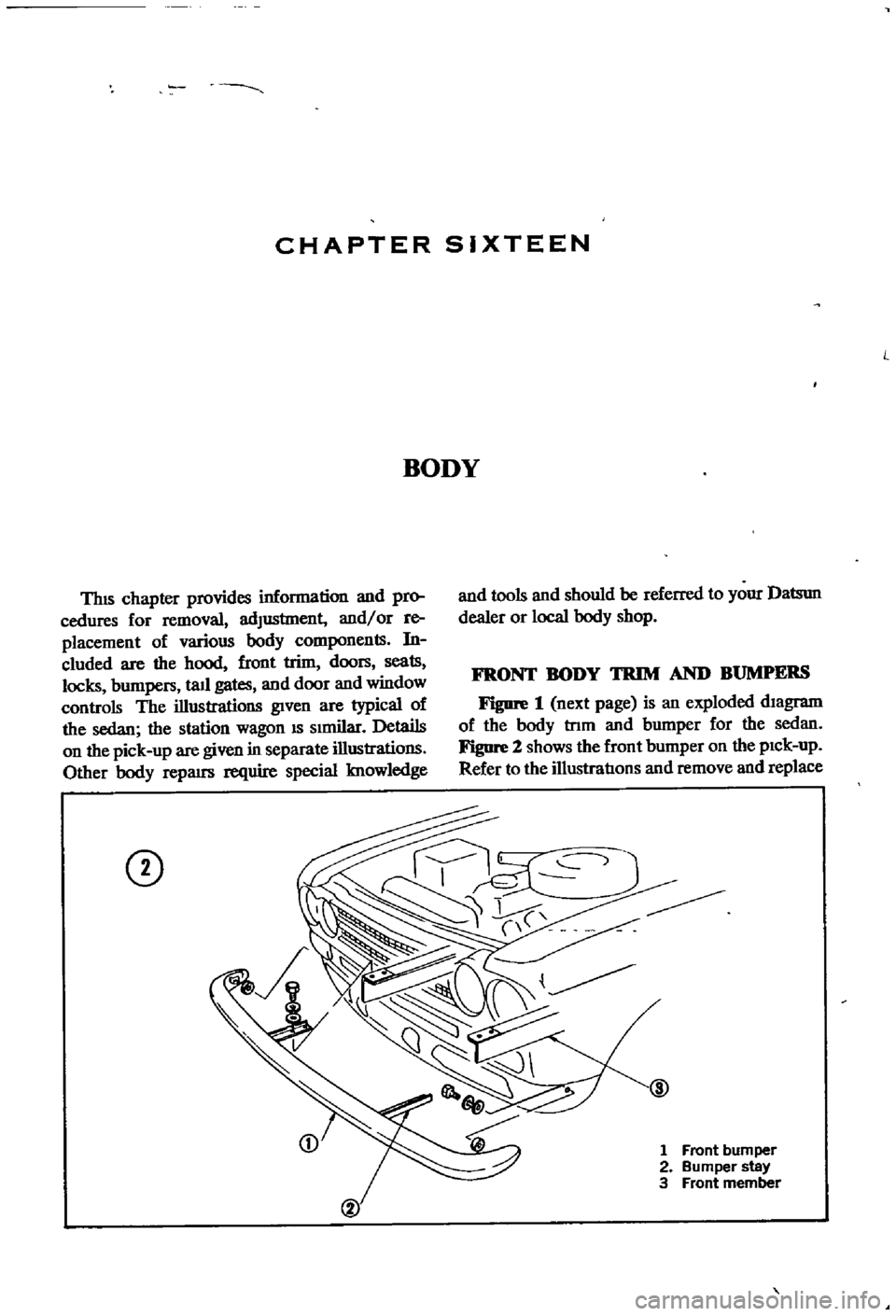
Figure
1
next
page
is
an
exploded
diagram
of
the
body
tnm
and
bumper
for
the
sedan
Figure
2
shows
the
front
bumper
on
the
pick
up
Refer
to
the
illustratIons
and
remove
and
replace
1
Front
bumper
2
Bumper
stay
3
Front
member
Page 232 of 252
BODY
225
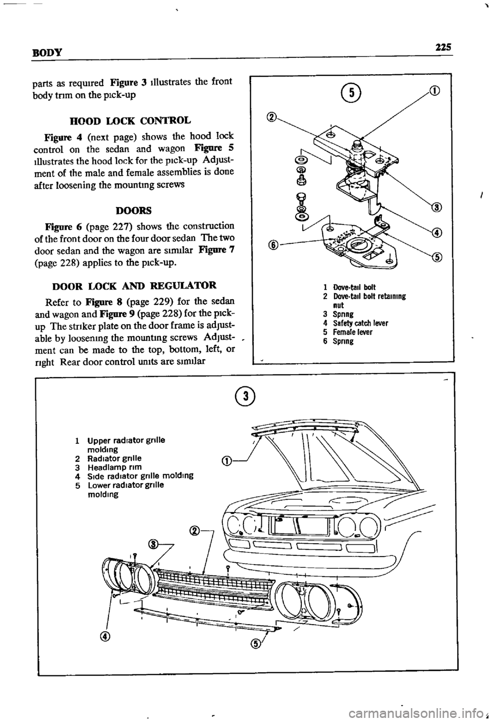
parts
as
requIred
Figure
3
Illustrates
the
front
body
tnm
on
the
pick
up
DOORS
Figure
6
page
227
shows
the
construction
of
the
front
door
on
the
four
door
sedan
The
two
door
sedan
and
the
wagon
are
slrmlar
Figure
7
page
228
applies
to
the
pick
up
o
HOOD
LOCK
CONTROL
Figure
4
next
page
shows
the
hood
lock
control
on
the
sedan
and
wagon
Figure
5
Illustrates
the
hood
lock
for
the
pick
up
AdJust
ment
of
the
male
and
female
assemblies
is
done
after
loosening
the
mountmg
screws
Gi
1
@
DOOR
LOCK
AND
REGULATOR
Refer
to
Figure
8
page
229
for
the
sedan
and
wagon
and
Figure
9
page
228
for
the
pick
up
The
strIker
plate
on
the
door
frame
is
adJust
able
by
loosenmg
the
mOWltmg
screws
AdJust
ment
can
be
made
to
the
top
bottom
left
or
nght
Rear
door
control
units
are
slnuIar
1
Dove
tall
bolt
2
Dove
tall
bolt
retaining
nut
3
Spnng
4
Safety
catch
lever
5
Female
lever
6
Spring
CD
1
Upper
radIator
gnlle
molding
2
RadIator
gnlle
3
Headlamp
nm
4
SIde
radIator
gnlle
molding
5
Lower
radIator
gnlle
molding
L
@
Page 235 of 252

228
CHAPTER
SIXTEEN
1
lock
knob
2
lock
installation
bolt
3
Bell
crank
installation
bolt
4
Door
lock
remote
control
assembly
5
Door
lock
assembly
6
OutsIde
handle
lever
7
InSide
lock
knob
IOstallatJon
bolt
CD
CD
D
00
TRUNK
LID
AND
BUMPER
Figure
10
page
230
shows
the
constructIon
details
of
the
sedan
trunk
lid
and
bumper
Figure
11
page
231
Illustrates
the
wagon
bumper
assembly
SEATS
Fre
12
page
232
IS
an
exploded
View
of
the
front
seat
and
mountIng
brackets
used
m
the
1
Door
panel
assembly
2
Door
Window
ventJlator
assembly
3
Door
Window
glass
4
Glass
run
5
Door
wmdow
weather
stnp
6
Door
outsIde
handle
7
Door
lock
key
cylinder
8
Door
lock
and
remote
control
assembly
9
Door
WIndow
regulator
10
InSIde
handle
11
Regulator
handle
12
Door
fimsh
13
Sealing
screen
14
Sealing
screen
15
Sealing
screen
16
Support
cushIon
@
FRONT
SEAT
FOR
PICK
UP
four
door
sedan
The
front
seats
and
mountmg
brackets
for
the
two
door
sedan
and
station
wagon
are
the
same
Figure
13
shows
the
seat
for
the
pIck
up
TAIL
GATE
Refer
to
Figure
14
page
233
for
details
of
the
statIon
wagon
tail
gate
Page 236 of 252
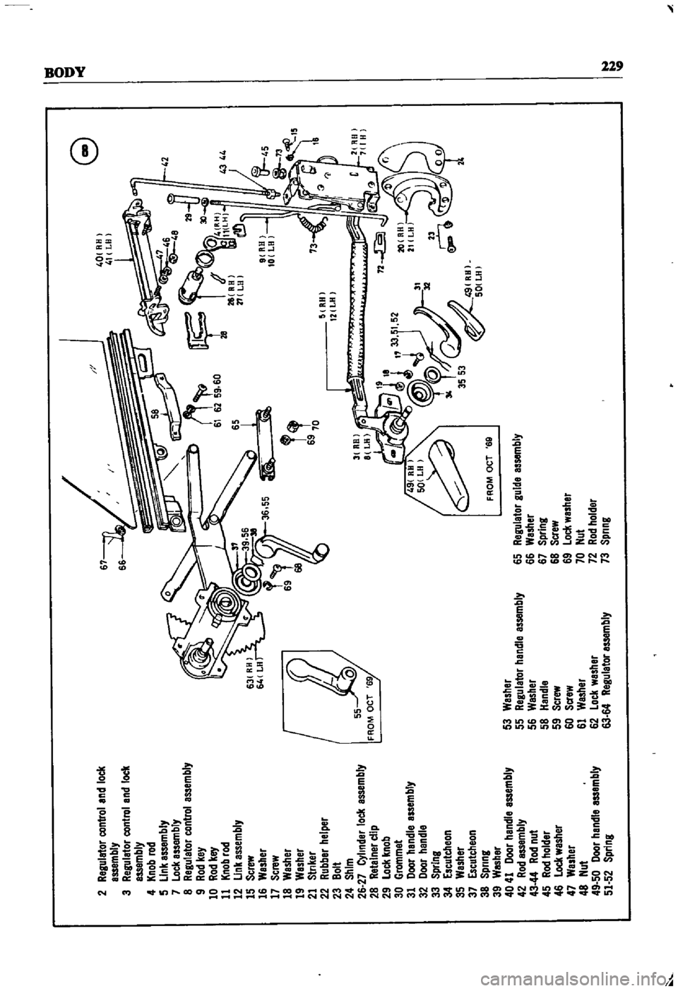
2
Regulator
control
and
lock
67
G
I
I
d
40
ftR
I
assembly
I
41
LH
1
3
Regulator
control
and
lock
assembly
4
Knob
rod
5
Link
assembly
7
Lock
assembly
r
U
V
46
JI
42
8
Regulator
control
assembly
9
Rod
key
10
Rod
key
11
Knob
rod
12
Unk
assembly
15
Screw
16
Washer
17
Screw
18
Washer
1t
19
Washer
21
Stnker
22
Rubber
helper
V
RHI
23
Bolt
I
12
LH
24
Shim
26
27
Cylinder
lock
assembly
28
RetaIner
dip
FROM
OCT
69
29
Lock
knob
IW
30
Grommet
31
Door
handle
assembly
32
Door
handle
33
Spring
34
Escutcheon
35
Washer
37
Escutcheon
3553
J
9
RH
38
Spring
501LH
39
Washer
F
ROM
OCT
eg
40
41
Door
handle
assembly
53
Washer
42
Rod
assembly
55
Regulator
handle
assembly
65
Regulator
guide
assembly
43
44
Rod
nut
56
Washer
66
Washer
45
Rod
holder
58
Handle
67
Spring
46
Lock
wesher
59
Screw
68
Screw
47
Washer
60
Screw
69
Lock
washer
48
Nut
61
Washer
70
Nut
49
50
Door
handle
assembly
62
Lock
washer
72
Rod
holder
51
52
Spring
63
64
Regulator
assembly
73
Spnng
N
Page 241 of 252
INDEX
A
Inspection
and
repair
191
Air
cleaner
Pad
replacement
190
Exploded
views
63
64
Piston
seal
replacement
193
Removal
and
replacement
62
Reassembly
and
installation
193
Removal
190
Air
pump
40
Brakes
front
pick
up
Alternator
Brushes
104
Adjustment
201
Diode
103
Exploded
View
195
Disassembly
98
ServiCing
194
SpecdicatIons
194
203
204
Exploded
Views
41
99
Brakes
rear
pick
up
Inspection
and
repair
101
Adjustment
202
Output
checks
104
Exploded
View
195
Reassembly
104
Servicing
194
Removal
40
98
Brakes
rear
sedan
and
wagon
Rotor
102
Adjustment
202
Stator
102
Exploded
view
194
Axle
removal
pick
up
175
Inspection
and
repair
193
Reassembly
194
B
Removal
and
disassembly
193
Breaker
points
110
Ball
JOint
lower
sedan
and
wagon
174
Bumpers
Battery
Exploded
view
front
pick
up
223
Inspecllon
aiii
I
servicing
21
Exploded
View
front
sedan
and
wagon
224
SpeCific
gravity
21
Exploded
view
rear
sedan
230
Body
Exploded
view
rear
wagon
231
Body
Irlm
and
bumpers
223
224
Door
lock
and
regulator
225
C
Doors
225
Hood
lock
control
225
Camshaft
Seats
228
DeSCription
34
Tail
gate
228
Exploded
view
37
Trunk
hd
and
bumper
228
Inspection
48
Brake
pedal
Reassembly
54
Inspection
and
repair
187
Sprocket
53
Installation
188
Tlmmg
chain
57
Removal
187
Carburetor
Brakes
Cleaning
and
inspection
75
Adjustment
201
202
Dash
pot
adjustment
71
Bleeding
196
DesCription
37
69
Brake
pedal
187
Disassembly
71
Front
diSC
sedan
and
wagon
190
193
Exploded
Views
74
75
Front
drum
pick
up
194
Fuel
level
adjustment
69
Handbrake
197
201
Idhng
adjustment
69
Master
cyhnder
188
Interlock
valve
70
Rear
pick
up
194
Reassembly
76
Rear
sedan
and
wagon
193
Removal
40
71
SpeCifications
and
service
data
203
204
Sectional
view
69
Troubleshooting
16
Throttle
valve
70
Wheel
cyhnders
pIck
up
196
Charging
system
Brakes
front
diSC
sedan
and
wagon
Troubleshooting
12
Adjustment
201
Choke
and
accelerator
Disassembly
191
Disassembly
and
installation
82
Exploded
view
192
Exploded
view
83