1968 DATSUN 510 water pump
[x] Cancel search: water pumpPage 4 of 252
II
CHAPTER
SIX
ENGINE
Cylmder
block
Crankshaft
PistOns
and
connectmg
rods
Cyhnder
head
Camshaft
Valve
mechamsm
Camshaft
dnve
Mamfolds
011
pump
Fuel
pump
Carburetor
Emission
control
devIces
Engme
removal
Engme
dISassembly
Pistons
and
connectmg
rods
Cyhnder
head
Engme
mspectIon
and
replllr
Engme
reassembly
Service
data
and
speCifications
CHAPTER
SEVEN
FUEL
SYSTEM
Air
cleaner
Fuel
strlllner
Fuel
pump
Carburetor
Fuel
tank
1
CHAPTER
EIGHT
COOLING
SYSTEM
DescnptIon
Water
pump
Fan
clutch
Thermostat
Radiator
CHAPTER
NINE
ENGINE
ELECTRICAL
SYSTEM
Starter
Overrunmng
clutch
assembly
ChargIng
ClrcUlt
Alternator
Alternator
output
Voltage
regulator
DIstrIbutor
Condenser
Igrntlon
cod
SpeCifications
Spark
plugs
CHAPTER
TEN
EMISSION
CONTROL
SYSTEM
Exhaust
emiSSIOn
control
Crankcase
emission
control
Air
mJectlon
system
Engme
modifications
Evaporative
emiSSion
control
Exhaust
system
CHAPTER
ELEVEN
CLUTCH
TRANSMISSION
AND
DRIVESHAFT
Clutch
TransmissIon
Master
cyhnder
TransmissIon
data
and
speCIfications
Operating
cyhnder
Dnveshaft
Withdrawal
lever
adjustment
Dnveshaft
data
and
speCIfications
Clutch
system
bleedmg
Automatic
transmIssIon
checks
Clutch
data
and
speCIfications
31
62
84
91
114
127
Page 31 of 252
26
CHAPTER
FOUR
2
Check
all
belts
hoses
and
fuellmes
Replace
If
reqUIred
Check
the
tensIon
of
the
belts
for
the
au
pump
and
the
alternator
Adjust
as
re
qUIred
Normal
deflection
of
the
belts
when
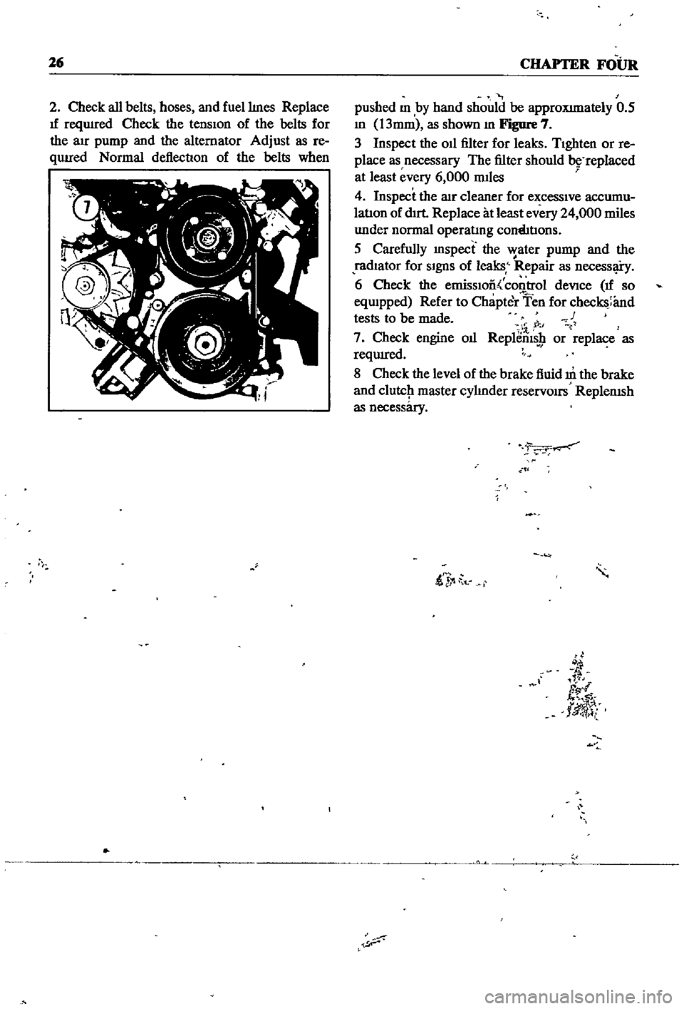
pushed
m
by
hand
should
be
approXImately
0
5
m
13mm
as
shown
m
Figure
7
3
Inspect
the
011
filter
for
leaks
TIghten
or
re
place
as
necessary
The
filter
should
replaced
at
least
every
6
000
mIles
4
Inspect
the
lIlr
cleaner
for
excessIve
accumu
latIon
of
dIrt
Replace
at
least
every
24
000
miles
under
normal
operatmg
cornhtIons
5
Carefully
mspect
the
water
pump
and
the
radIator
for
SIgnS
of
leaks
Repair
as
necessl
i
y
6
Check
the
emissIoo
control
deVice
If
so
eqwpped
Refer
to
Chapter
Ten
for
checks
and
tests
to
be
made
c
1
7
Check
engine
oIl
Replems
9
or
replace
as
reqUIred
8
Check
the
level
of
the
brake
fluid
m
the
brake
and
clutcJ1
master
cylmder
reservOirs
ReplenISh
as
necessary
ii
t
d
fl
tlJ
l
Page 38 of 252
4l
4111a
78
mml
la78mml
42
4
42
4OIla50mml
t
4544
i
35
45
lIq
D
1
43
45
44
6
1i
45
43
42
41
45
44
46
46
47
8
78mml
I
Tlmmg
Indicator
48
lock
washer
spring
49
Water
Inlet
50
Rubber
cap
51
Rubber
cap
52
Hosa
clamp
53
Inlet
watar
gasket
54
Hex
bolt
55
lock
washer
spring
56
Connector
57
011
filter
cartndge
58
front
engme
cover
59
61
Bloel
cyllndelllner
18
15
58
57
1
Cylinder
block
assembly
2
Main
beanng
bolt
3
Dowel
4
Block
dowel
5
Block
dowel
6
Block
to
transmIssIon
case
dowel
7
Tlmmg
chaIn
covar
dowel
8
Welch
plug
9
Taper
plug
10
Crankcase
011
seal
11
Bearing
011
seal
12
Drain
plug
13
011
pressure
sWitch
14
011
level
gauge
guide
15
Oll
evel
gauga
r1
26
54
25
011
pan
gasket
26
Hax
bolt
27
lock
Sprl
ng
washer
28
011
cooler
hose
clamp
29
Hose
cl
mp
30
Tube
clamp
31
Tube
clamp
32
Clamp
spacer
33
Hex
bolt
34
Washer
35
Crankcase
011
seel
36
Waler
pump
dowel
37
Water
pump
dowel
38
RIght
hand
front
caver
gasket
39
left
hand
front
cover
gasket
40
Hex
bolt
41
Hex
bolt
42
lock
washer
spnng
43
Hex
bolt
44
Hex
bolt
45
Lock
washer
spring
46
Tlmmg
Indicator
47
IndIcator
rivet
22
16
23
Drain
plug
washer
24
Dram
plug
e
l
lIlI
1M
1M
Page 41 of 252
36
CHAPTER
SIX
0B
34
35
2224
19
21
p
7
31
13
4
7
O
41
rlj
17
11
lOlL
JET
2
Intake
valve
Insert
3
Exhaust
valve
Insert
4
Intake
valve
guide
5
Exhaust
valve
guide
3
2
7
Od
gallery
taper
plug
I
441
J
8
Cylinder
blind
plug
9
Cylinder
blind
plug
10
Taper
plug
21
Washer
34
Rocker
cover
44
Spnng
washer
11
Cylinder
head
011
jet
22
Front
head
cover
35
Rocker
cover
gasket
45
Water
outlet
12
stud
23
Bolt
36
Od
filler
cap
46
JOint
washer
13
stud
24
Front
cover
head
gasket
37
011
cap
paclung
47
stud
14
stud
28
Hex
bolt
38
Rocker
cover
bolt
48
Hex
nut
15
Stud
29
lock
washer
spring
39
Thennostat
a5sem
bly
49
Spring
washer
17
Cylinder
head
gasket
30
Engine
front
Slinger
40
Thennostat
hOUSing
50
Water
temperature
gauge
18
Cylinder
head
bolt
31
Engine
rear
slinger
41
Thennostat
gasket
51
Water
temperature
ground
nut
19
Cylinder
head
bolt
32
Spnng
washer
42
Hex
bolt
53
Cam
bracket
bolt
20
Cylinder
head
bolt
33
Hex
nut
43
Hex
bolt
54
Cam
bracket
bolt
shoe
type
of
tensIOner
reduces
vibration
and
controls
overall
cham
tenSIOn
MANIFOLDS
The
intake
and
exhaust
manifolds
are
shown
in
Figure
10
The
intake
mamfold
IS
made
out
of
cast
aluminum
and
the
eXhaustof
casn
roir
OIL
PUMP
The
oil
pump
is
mounted
to
the
bottom
left
hand
side
of
the
front
cover
Refer
to
the
pre
@
Page 43 of 252
38
CHAPTER
SIX
EMISSION
CONTROL
DEVICES
All
Datsuns
have
a
sealed
type
of
crankcase
emISSion
control
device
and
an
exhaust
emISsion
control
deVice
Models
sold
m
Cahfornla
smce
1970
also
have
an
evaporative
emisSion
control
deVice
An
rmportant
part
of
the
exhaust
control
device
is
the
air
pump
located
at
the
bottom
left
hand
side
of
the
engme
It
IS
dnven
by
a
belt
off
of
the
crankshaft
pulley
and
supphes
air
to
the
exhaust
system
In
1972
an
electric
blower
in
corporated
m
the
air
cleaner
replaced
the
mechanical
pumI
ENGINE
REMOVAL
Expenence
has
shown
It
IS
easier
to
remove
the
engine
and
the
transmission
as
a
smgle
UnIt
than
to
remove
the
engme
alone
Once
the
en
gine
and
transmiSSIon
are
out
of
the
vehIcle
the
tranSmIssion
can
be
detached
from
the
engme
To
remove
the
engme
transmISsion
proceed
as
follows
1
Scribe
ahgnment
marks
on
the
hood
around
the
hmges
ThIS
will
make
remstallatlon
eaSIer
2
Remove
the
two
bolts
that
secure
each
hInge
and
remove
the
hood
It
is
not
necessary
to
re
move
the
hood
support
from
the
engme
firewall
3
DISconnect
the
lower
radIator
hose
from
the
right
hand
SIde
of
the
engine
and
at
the
bottom
of
the
radIator
ThIS
will
pernnt
coolant
to
dram
from
the
engme
and
the
radIator
4
Remove
the
draIn
plugs
from
the
engine
pan
and
translIDSsIon
and
completely
dram
lubn
cants
Into
suitable
contamers
5
DISconnect
the
battery
cables
from
the
bat
tery
loosen
the
two
hold
down
clamps
and
re
move
the
battery
NOTE
The
location
and
number
of
hoses
to
be
removed
from
the
air
cleaner
varies
from
model
to
model
It
IS
normally
easier
to
remove
the
hoses
from
the
sources
rather
than
try
to
dISconnect
them
from
yndemeath
the
air
cleaner
The
1972
model
Will
requlre
dlsconnectlOn
of
the
electrica1
cirCUit
In
the
air
cleaner
system
wing
nut
from
the
top
of
the
air
cleaner
and
remove
the
aIr
cleaner
7
DIsconnect
the
upper
radiator
hose
from
the
radiator
and
the
thermostat
housmg
Remove
the
hose
8
Disconnect
the
two
heater
hoses
from
the
nght
hand
side
of
the
engme
TIe
these
bac
so
they
won
t
interfere
with
removal
of
the
engme
9
Remove
the
radIator
grille
by
unscrewing
all
mountmg
screws
10
Remove
the
four
mounting
screws
holding
the
fan
shield
to
the
backside
of
the
radiator
11
Remove
the
four
mountmg
bolts
holdIng
the
radiator
In
place
In
automatic
tranSmISsion
models
dISconnect
the
two
transnnsslOn
oIl
cooler
lInes
from
the
bottom
of
the
radiator
Pull
the
radiator
straight
up
to
remove
Remove
the
fan
shield
12
Loosen
the
adjustment
and
mounting
bolts
from
the
retamIng
brackets
on
the
alternator
and
air
pump
If
so
eqwpped
The
alternator
is
lo
cated
at
the
bottom
nght
hand
Side
of
the
engme
and
the
air
pump
on
the
lower
left
hand
Side
13
Loosen
tenSIon
on
the
two
dnve
belts
re
move
the
belts
from
the
alternator
and
air
pump
and
then
from
the
fan
pulleys
14
Remove
the
bolts
holdIng
the
fan
and
pulley
to
the
water
pump
assembly
and
remove
the
fan
and
pulley
15
DISconnect
the
fuel
hne
from
the
fuel
pump
16
DIsco
ect
accelerator
control
linkage
and
choke
WIre
at
the
carburetor
17
Disconnect
the
wiring
from
the
starter
motor
alternator
Ignition
coIl
oIl
pressure
switch
and
temperature
transmItting
unit
NOTE
The
following
steps
are
per
formed
from
under
the
car
lack
up
the
front
of
the
car
and
position
stands
under
the
front
support
points
to
proVide
working
room
under
the
vehicle
WARNING
Never
climb
under
a
vehicle
that
is
supported
by
the
lack
only
If
stands
are
not
avflllable
sturdy
wooden
blocks
can
be
U3ed
6
Disconnect
all
hoses
that
lead
to
the
air
cleaner
remove
two
bolts
that
hold
the
air
cleaner
to
its
mountmg
bracket
unscrew
the
18
Remove
two
bolts
holdIng
the
clutch
operat
Ing
cylInder
to
the
flywheel
hOUSIng
shown
m
Page 47 of 252
4Z
CHAPTER
SIX
the
adJustmg
bar
mto
the
mountmg
flange
of
the
arr
pump
2
Remove
the
bolt
lInking
the
arr
pump
to
the
mountmg
bracket
and
remove
pump
3
The
bracket
has
four
bolts
to
the
engme
the
adJustmg
bar
mounts
on
the
front
cover
WIth
two
bolts
Remove
these
to
free
the
front
cover
Water
Pump
Removal
I
Remove
the
bolts
and
lockwashers
Jommg
the
water
pump
to
the
front
cover
The
number
of
bolts
vanes
from
year
to
year
due
to
pump
aesign
clianges
Remove
water
pump
Fuel
Pump
Removal
I
Remove
the
two
nuts
and
lockwashers
secur
mg
fuel
pump
to
the
engIne
and
remove
pump
Rocker
Arm
COYer
Removal
I
Remove
SIX
bolts
holdmg
rocker
arm
cover
to
head
and
lIft
off
cover
Intake
and
Exhaust
Manifold
Removal
I
Remove
eleven
nuts
and
lockwashers
that
secure
the
mtake
and
exhaust
manIfolds
2
Remove
mtake
and
exhaust
manIfolds
as
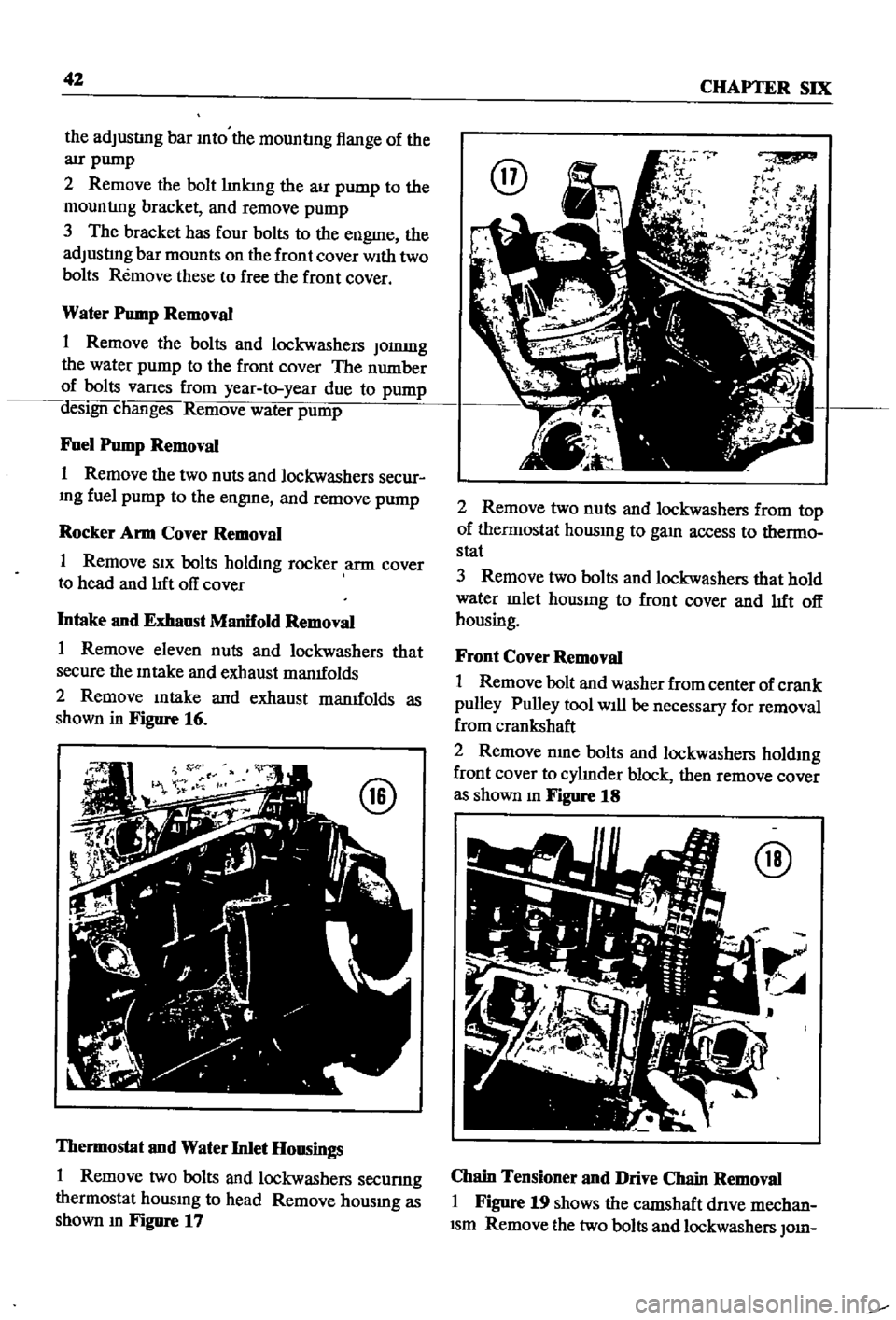
shown
in
Figure
16
Thermostat
and
Water
Inlet
Housings
1
Remove
two
bolts
and
lockwashers
secunng
thermostat
housmg
to
head
Remove
housmg
as
shown
m
Figure
17
@
2
Remove
two
nuts
and
lockwashers
from
top
of
thermostat
housmg
to
gam
access
to
thermo
stat
3
Remove
two
bolts
and
lockwashers
that
hold
water
mlet
housmg
to
front
cover
and
lIft
off
housing
Front
Cover
Removal
1
Remove
bolt
and
washer
from
center
of
crank
pulley
Pulley
tool
Will
be
necessary
for
removal
from
crankshaft
2
Remove
nme
bolts
and
lockwashers
holdmg
front
cover
to
cylInder
block
then
remove
cover
as
shown
m
Figure
18
@
Chain
Tensioner
and
Drive
Chain
Removal
I
Figure
19
shows
the
camshaft
dnve
mechan
Ism
Remove
the
two
bolts
and
lockwashers
010
Page 63 of 252
58
CHAPTER
SIX
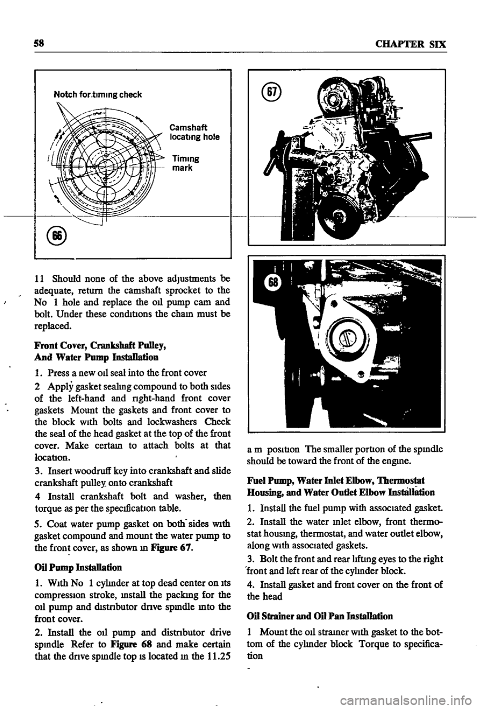
Notch
for
t1mmg
check
Camshaft
locatmg
hole
Timmg
mark
11
Should
none
of
the
above
adjustments
be
adequate
return
the
camshaft
sprocket
to
the
No
1
hole
and
replace
the
Oll
pump
cam
and
bolt
Under
these
conditIons
the
cham
must
be
replaced
Front
Cover
Crankshaft
Polley
And
Water
Pomp
InstaDation
1
Press
a
new
Oll
seal
into
the
front
cover
2
Apply
gasket
seahng
compound
to
both
sides
of
the
left
hand
and
nght
hand
front
cover
gaskets
Mount
the
gaskets
and
front
cover
to
the
block
With
bolts
and
lockwashers
Check
the
seal
of
the
head
gasket
at
the
top
of
the
front
cover
Make
certam
to
attach
bolts
at
that
locatlon
3
Insert
woodruff
key
into
crankshaft
and
slide
crankshaft
pulley
onto
crankshaft
4
Install
crankshaft
bolt
and
washer
then
torque
as
per
the
speclficatlon
table
5
Coat
water
pump
gasket
on
both
sides
With
gasket
compound
and
mount
the
water
pump
to
the
front
cover
as
shown
m
Figure
67
Oil
Pump
Installation
1
With
No
1
cyhnder
at
top
dead
center
on
Its
compressIOn
stroke
mstall
the
packing
for
the
Oll
pump
and
distnbutor
dnve
spmdle
mto
the
front
cover
2
Install
the
Oll
pump
and
distnbutor
drive
spmdle
Refer
to
Figure
68
and
make
certain
that
the
dnve
spmdle
top
IS
located
m
the
11
25
@
a
m
position
The
smaller
portion
of
the
spmdle
should
be
toward
the
front
of
the
engme
Fuel
Pomp
Water
Inlet
Elbow
lbermostat
Housing
and
Water
Outlet
Elbow
InstliJIation
1
Install
the
fuel
pump
with
associated
gasket
2
Install
the
water
mlet
elbow
front
thermo
stat
housmg
thermostat
and
water
outlet
elbow
along
With
associated
gaskets
3
Bolt
the
front
and
rear
hftmg
eyes
to
the
right
front
and
left
rear
of
the
cyhnder
block
4
Install
gasket
and
front
cover
on
the
front
of
the
head
Oil
Strainer
and
Oil
Pan
Installation
1
Mount
the
011
stramer
With
gasket
to
the
bot
tom
of
the
cyhnder
block
Torque
to
specifica
tion
Page 64 of 252

ENGINE
59
2
Coat
the
pan
gasket
on
both
sides
With
gasket
compound
and
attach
the
oil
pan
to
the
cyhnder
block
Torque
as
specIfied
Manifold
and
Carburetor
Installation
1
Install
the
mtake
and
exhaust
manIfolds
WIth
associated
gasket
to
the
cylmder
head
2
Mount
the
carburetor
and
gasket
to
the
mtake
manIfold
2
Adjust
all
mtake
and
exhaust
valves
to
the
specIfied
clearance
for
a
cold
engme
Clutch
Assembly
Installation
CAUTION
Take
extreme
care
not
to
get
grease
or
011
on
the
clutch
or
flywheel
frlc
hon
contact
surfaces
1
Place
the
clutch
disc
assembly
on
the
flywheel
With
the
longer
chamfered
splmed
end
of
the
dISC
toward
the
transmISSion
2
Visually
align
or
use
a
dummy
splmed
dnve
shaft
to
ahgn
the
diSC
assembly
With
the
flywheel
pilot
beanng
3
Install
and
tighten
the
SIX
bolts
holdmg
the
clutch
cover
assembly
to
the
flywheel
Tighten
the
bolts
a
turn
each
tune
by
diagonal
pattern
until
they
are
tight
Tlghtenmg
torque
should
be
174
to
188ft
lbs
24
to
2
6
kg
m
NOTE
There
are
two
dowels
on
the
flywheel
to
locate
the
clutch
cover
4
Remove
dummy
shaft
If
used
after
the
above
bolts
are
fully
tightened
5
Refit
the
release
bearing
and
translI11Ssion
case
Miscellaneous
Installation
1
Connect
the
fuel
hose
on
the
front
part
of
the
engme
to
the
fuel
pump
and
to
the
carburetor
2
Gap
the
spark
plugs
and
mstall
them
usmg
new
gaskets
3
Coat
the
rocker
arm
cover
gasket
With
sealer
and
position
It
on
the
cylmder
head
4
Install
the
rocker
arm
cover
and
tighten
the
two
thumb
screws
that
hold
it
m
place
5
Install
distrIbutor
makmg
certam
that
the
notch
on
the
distributor
shaft
assembly
mates
With
the
drive
spmdle
Ahgn
the
location
marks
made
dunng
disassembly
so
that
the
distrIbutor
is
positioned
as
before
6
Install
and
tighten
the
bolts
which
hold
the
dIStributor
to
the
front
cover
7
Install
pomts
condenser
and
rotor
8
Replace
distrIbutor
cap
and
attach
spark
plug
Wires
m
the
correct
sequence
Make
certain
that
all
wires
are
firmly
seated
m
the
distrIbutor
cap
and
attached
securely
to
the
spark
plugs
9
HOISt
the
engme
assembly
from
the
work
stand
10
Install
the
alternator
bracket
alternator
and
engme
mounts
to
the
block
11
Install
the
IgnItIon
coil
oil
filter
oil
pressure
SWitch
dipstick
and
water
drain
plug
12
Connect
the
vacuum
Ime
between
the
dis
trIbutor
and
carburetor
13
Connect
the
transIDlSSlOn
to
the
engine
prior
to
mstallatIon
m
the
vehicle
Engine
Installation
Installation
is
the
reverse
of
the
procedures
followed
m
removal
Be
certaIn
thatlall
battery
connections
are
made
that
water
hoses
are
se
cured
wmng
IS
connected
properly
and
that
all
required
bolts
and
mounts
are
mstalled
and
tightened
Replace
the
radiator
fan
belts
and
radiator
shroud
Fill
the
engme
With
the
proper
grade
of
oil
and
the
radiator
With
recommended
coolant
Install
the
hood
to
the
hInges
according
to
the
marks
made
dUrIng
removal
SERVICE
DATA
AND
SPECIFICATIONS
Table
1
covers
servIce
data
and
engme
Speci
fications