1968 DATSUN 510 brake rotor
[x] Cancel search: brake rotorPage 21 of 252
16
CHAPTER
TIlREE
sary
Also
check
all
parts
for
mlSaltgnment
and
uneven
wear
TRANSMISSION
1
Difficult
to
mesh
gears
Make
certam
the
clutch
pressure
plate
and
re
lease
beanng
are
m
good
condItion
The
trouble
can
be
caused
by
worn
gears
shaft
and
or
bear
mgs
DISassemble
and
repaIr
as
requIred
Also
can
be
caused
by
msufficlent
operatmg
stroke
due
to
worn
or
loose
sltdmg
parts
or
a
defective
synchronIZer
DIsassemble
carefully
InSpect
and
replace
as
requIred
2
Gears
slip
out
of
mesh
Generally
thIS
trouble
occurs
when
the
mterlock
plunger
check
ball
and
or
spnng
IS
weakened
or
worn
The
trouble
can
also
be
caused
by
worn
fork
rod
ball
groove
damaged
bearings
or
dam
aged
gears
DIsassemble
carefully
mspect
and
replace
as
required
3
NOIse
If
nOISes
are
heard
wIth
the
engme
idlmg
and
the
clutch
disengaged
the
nOIse
IS
probably
conung
from
the
transmISSIOn
Several
Items
can
cause
nOISes
either
smgly
or
m
combmatIon
Check
the
qualIty
and
quantity
of
lubrIcant
in
the
trans
mISSIon
Replace
or
replenISh
as
necessary
Worn
bearIngs
wIll
usually
produce
a
lugh
humming
at
hIgh
speed
and
a
cycltc
knockIng
sound
at
low
speed
Worn
or
damaged
splInes
and
bushmgs
will
also
cause
nOIse
BRAKES
1
Brake
pedal
goes
to
floor
There
are
numerous
causes
for
thIS
includIng
excessIvely
worn
Itnmgs
aIr
in
the
hydraultc
sys
tem
leaky
brake
lmes
leaky
wheel
cylmders
or
leaky
or
worn
master
cylmder
Check
for
leaks
and
thIn
brake
linmgs
Bleed
and
adjust
the
brakes
If
thIS
doesn
t
cure
the
trouble
rebwld
wheel
cylmders
a
nd
or
master
cylmder
2
Spongy
pedal
Normally
caused
by
aIr
m
the
system
blee
d
and
adjust
the
brakes
3
Brakes
pull
Check
brake
adjustment
Also
check
for
contam
inated
brake
Itmngs
from
leaks
leaky
wheel
cyltnders
loose
caltpers
frozen
or
seIZed
pIstons
and
restrIcted
brake
lmes
or
hoses
In
addItion
check
front
end
alignment
and
suspensIOn
dam
age
such
as
broken
front
or
rear
sprmgs
shocks
etc
Check
condItIon
of
tIres
4
Brakes
squeal
or
chatter
Check
brake
lmmg
thickness
and
brake
drum
roundness
Ensure
that
the
shoes
have
cham
ferred
ends
and
are
not
loose
Inspect
the
condI
tion
of
the
rotors
on
the
front
wheel
dISC
brakes
to
make
certain
they
are
not
scored
or
damaged
Clean
away
all
dIrt
on
shoes
pads
rotors
or
drums
5
Draggmg
brakes
Check
brake
adjustment
includmg
handbrake
Check
for
broken
or
weak
shoe
return
springs
swollen
rubber
parts
due
to
unproper
brake
flUId
or
other
contammatIon
Clean
or
replace
de
fectIve
parts
6
Hard
pedal
Check
brake
linmgs
for
contammation
Also
check
for
restrIcted
brake
lines
and
hoses
7
High
speed
fade
Check
for
dIstorted
or
out
of
round
drums
and
contamInated
brake
lmmgs
Make
certam
the
recommended
brake
flUId
IS
used
Dram
entIre
system
and
refill
If
In
doubt
8
Pulsatmg
pedal
Check
for
dIStorted
or
out
of
round
drums
or
rotors
Check
for
excessIVe
brake
dISC
run
out
STEERING
AND
SUSPENSION
NOTE
Unusual
steermg
pullmg
or
wandermg
IS
usually
caused
by
bent
or
otherwise
mIsaligned
suspenszon
parts
Because
of
the
speCialized
equIp
ment
reqUired
to
evaluate
and
correct
these
faults
It
IS
recommended
t
tat
servIce
to
the
steermg
and
suspension
system
be
referred
to
your
Datsun
dealer
oca
quallfied
specrallst
m
thiS
field
1
VibratIOn
felt
m
steermg
wheel
VIbratIon
can
be
caused
by
several
thmgs
includ
ing
lll1proper
aIr
pressure
m
tIres
uneven
wear
Page 173 of 252
CHAPTER
THIRTEEN
FRONT
AXLE
FRONT
SUSPENSION
AND
STEERING
A
strut
type
front
suspension
IS
used
on
sedans
and
wagons
The
shock
absorber
and
the
spmdle
are
a
smgle
urnt
which
is
supported
by
a
coIl
spnng
on
the
upper
end
and
by
the
trans
verse
lInk
on
the
lower
end
Figures
1
2
nnd
3
are
exploded
dIagrams
of
the
axle
and
suspen
SIon
system
used
FIgure
1
Illustrates
the
axle
Figure
2
shows
the
sedan
suspenSlOn
and
FIgure
3
covers
the
wagon
Front
suspensIOn
on
the
pIck
up
IS
a
double
wIShbone
mdependent
deSign
which
uses
torsIon
bars
Figure
4
IS
a
cross
sectional
view
WHEEL
HUB
AND
WHEEL
BEARING
SEDAN
AND
WAGON
Wheel
Hub
nnd
Wheel
Bearing
Removal
Sednn
aud
Wagon
1
Jack
up
the
front
of
the
vehicle
and
support
It
on
stands
2
Remove
the
wheels
3
Detach
brake
hose
connector
at
frame
4
Remove
calIper
fiXlng
bolts
and
then
cahper
See
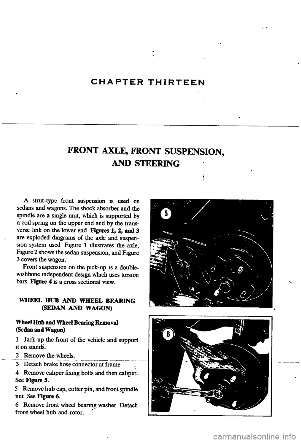
Figure
5
5
Remove
hub
cap
cotter
pin
and
front
spindle
nut
See
Figure
6
6
Remove
front
wheel
bearmg
washer
Detach
front
wheel
hub
and
rotor
ft
V
0
y
F
I
I
J
j
0
l
l
4
f
Page 195 of 252
190
CHAPTER
FOURTEEN
Master
Cylinder
Assembly
and
Installation
I
Assemble
the
master
cyhnder
m
the
reverse
order
of
dIsassembly
2
Pnor
to
assembly
soak
piston
cap
m
brake
flwd
Install
piston
so
that
It
seats
firmly
on
the
piston
cup
3
Coat
the
cyhnder
bore
and
pISton
assemblies
With
clean
brake
flwd
before
assembly
4
When
assembly
IS
complete
mount
master
cylmder
on
dash
wall
and
hook
connecting
rod
to
brake
pedal
Replace
return
sprmg
Fill
the
reservOir
With
clean
brake
flUid
5
If
aIr
has
seeped
mto
the
brake
Imes
bleed
the
brakes
as
descnbed
later
m
thIS
chapter
FRONT
DISC
BRAKES
SEDAN
AND
WAGON
Brake
Pad
Replacement
Pad
wear
should
be
checked
every
4
000
nuIes
Clearance
between
the
pad
and
the
rotor
IS
adjusted
automatIcally
and
therefore
IS
not
a
wear
mdlcator
Pad
thiCknesS
IS
checked
by
re
movmg
the
antI
rattle
clJp
When
the
pad
hning
becomes
worn
to
0
04
Imm
replace
all
pads
on
the
front
wheels
I
Remove
the
hub
cap
loosen
the
hub
nuts
jack
up
the
vehicle
support
with
stands
and
remove
the
front
wheels
2
Remove
the
antI
rattle
clJp
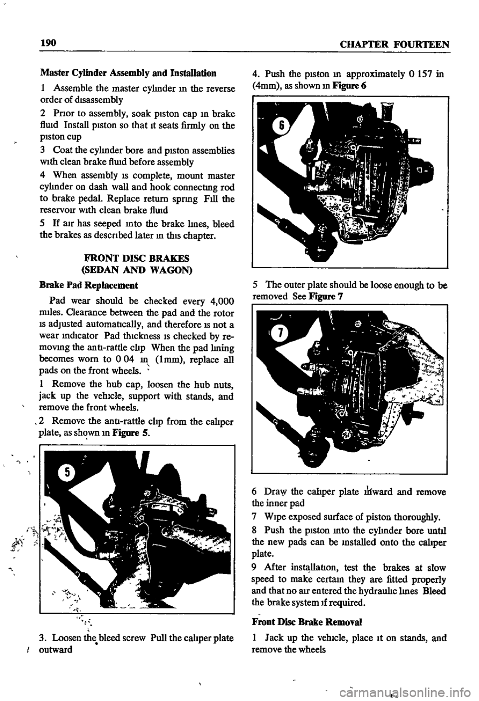
from
the
caliper
plate
as
shown
m
Figure
S
jty
3
Loosen
the
bleed
screw
Pull
the
calJper
plate
outward
4
Push
the
pISton
m
approximately
0
157
in
4mm
as
shown
m
Figure
6
5
The
outer
plate
should
be
loose
enough
to
be
removed
See
Figure
7
6
Dra
y
the
calJper
plate
rlfward
and
remove
the
inner
pad
7
Wipe
exposed
surface
of
piston
thoroughly
8
Push
the
piston
mto
the
cyhnder
bore
untJI
the
new
pads
can
be
mstalled
onto
the
calJper
plate
9
After
instl
llatIon
test
the
brakes
at
slow
speed
to
make
certam
they
are
fitted
properly
and
that
no
au
entered
the
hydraul1c
hnes
Bleed
the
brake
system
If
required
Front
Disc
Brake
Removal
I
Jack
up
the
vehicle
place
It
on
stands
and
remove
the
wheels
P
Page 196 of 252
BRAKES
191
2
Disconnect
the
front
brake
hose
from
the
brake
tube
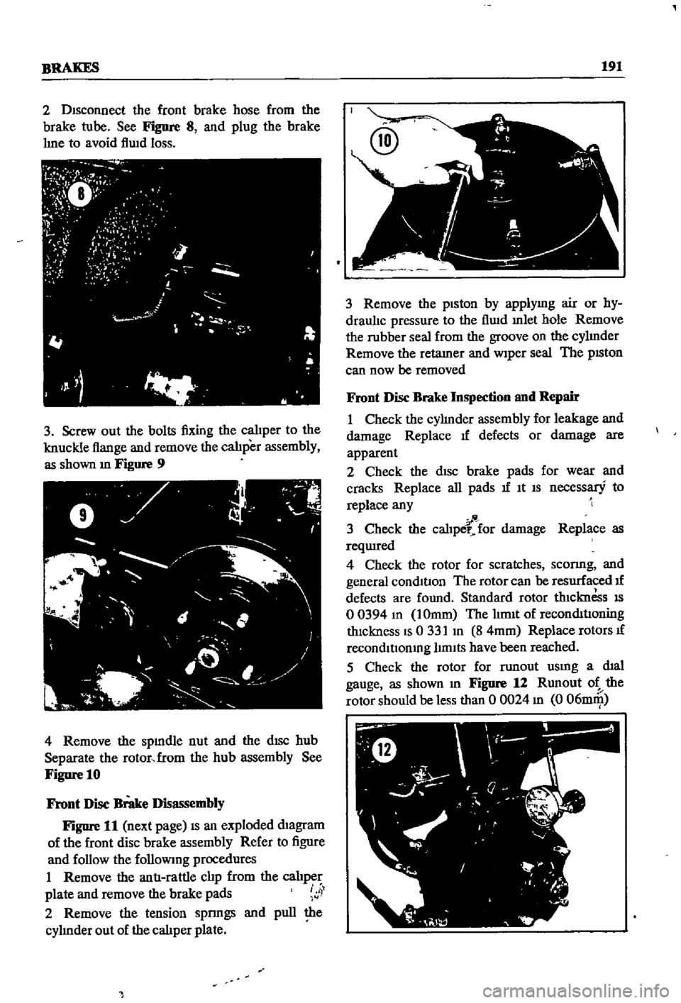
See
Figure
8
and
plug
the
brake
hne
to
avoid
flwd
loss
3
Screw
out
the
bolts
fixing
the
calJper
to
the
knuckle
flange
and
remove
the
calJper
assembly
as
shown
m
Figure
9
4
Remove
the
spmdle
nut
and
the
dISC
hub
Separate
the
rotor
from
the
hub
assembly
See
Figure
10
Front
Disc
Brake
Disassembly
Figure
11
next
page
IS
an
exploded
diagram
of
the
front
disc
brake
assembly
Refer
to
figure
and
follow
the
followmg
procedures
I
Remove
the
antI
rattle
clip
from
the
calJper
plate
and
remove
the
brake
pads
4
2
Remove
the
tension
spnngs
and
pull
the
cyhnder
out
of
the
caliper
plate
3
Remove
the
piston
by
applymg
air
or
hy
draulJc
pressure
to
the
flwd
mlet
hole
Remove
the
rubber
seal
from
the
groove
on
the
cyhnder
Remove
the
retamer
and
Wiper
seal
The
pISton
can
now
be
removed
Front
Disc
Brake
Inspection
and
Repair
I
Check
the
cyhnder
assembly
for
leakage
and
damage
Replace
If
defects
or
damage
are
apparent
2
Check
the
disc
brake
pads
for
wear
and
cracks
Replace
all
pads
If
It
IS
necessary
to
replace
any
fi
3
Check
the
caliper
for
damage
Replace
as
reqUIred
4
Check
the
rotor
for
scratches
sconng
and
general
conditIon
The
rotor
can
be
resurfaced
If
defects
are
found
Standard
rotor
thiCknesS
IS
o
0394
m
IOmm
The
hm1t
of
reconditIOning
thickness
IS
0
331
m
8
4mm
Replace
rotors
If
recondltIomng
limits
have
been
reached
5
Check
the
rotor
for
TWlout
usmg
a
dial
gauge
as
shown
m
Figure
12
Rnnout
ot
the
rotor
should
be
less
than
0
0024
m
0
06DlIll
Page 208 of 252
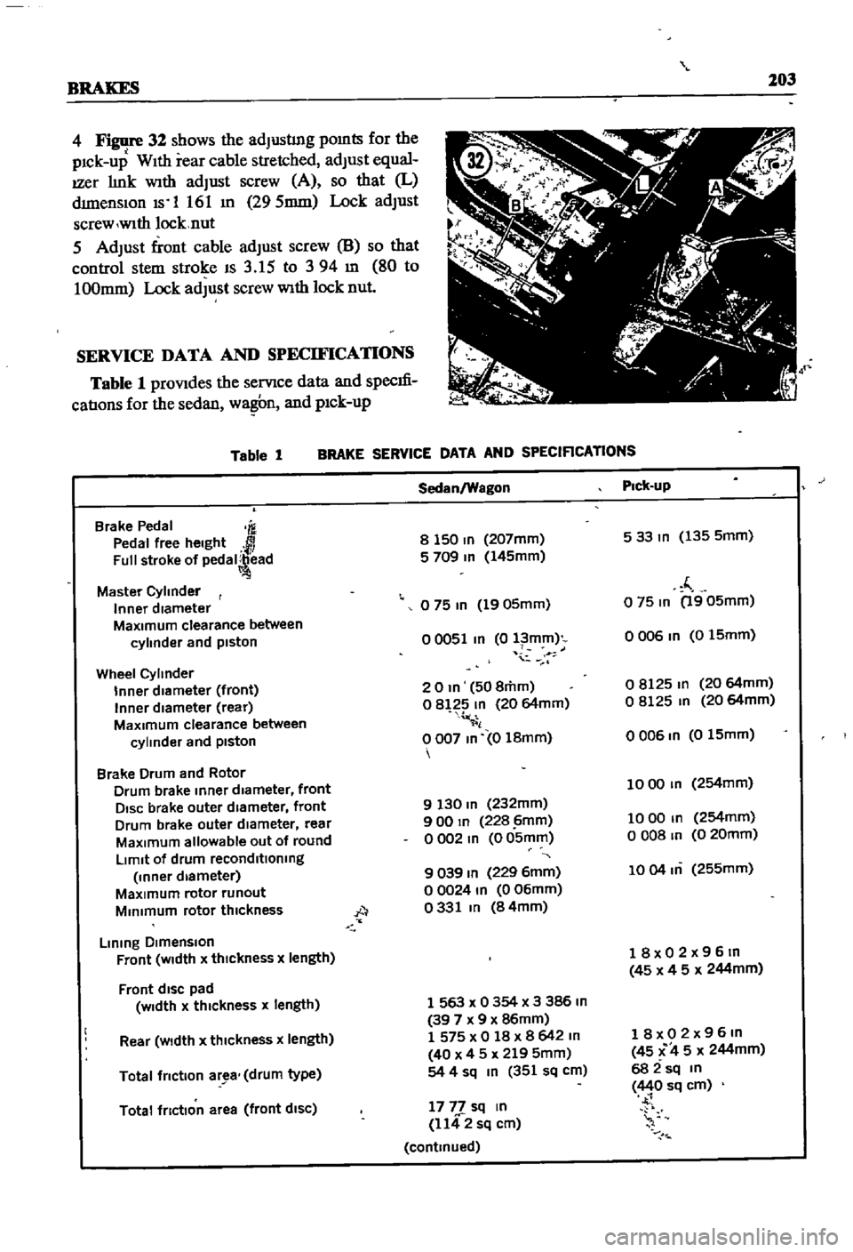
BRAKES
203
4
32
shows
the
adJusting
pomts
for
the
pick
up
With
rear
cable
stretched
adJust
equal
IZer
link
With
adJust
screw
A
so
that
L
dimensiOn
Is
1
161
m
295mm
Lock
adJust
screw
wlth
locknut
5
AdJust
front
cable
adJust
screw
8
so
that
control
stem
stroke
IS
3
15
to
394
m
80
to
100mm
Lock
adJust
screw
With
lock
nut
SERVICE
DATA
AND
SPECIFICATIONS
Table
1
prOVides
the
servIce
data
and
specm
catIons
for
the
sedan
wa
n
and
pick
up
Table
1
BRAKE
SERVICE
DATA
AND
SPECIRCATlONS
Brake
Pedal
m
Pedal
free
height
Full
stroke
of
pedal
ead
Master
Cylinder
Inner
diameter
MaXImum
clearance
between
cylinder
and
piston
Wheel
Cylinder
Inner
diameter
front
Inner
diameter
rear
MaXimum
clearance
between
cylinder
and
piston
Brake
Drum
and
Rotor
Drum
brake
Inner
diameter
front
DISC
brake
outer
diameter
front
Drum
brake
outer
diameter
rear
MaXimum
allowable
out
of
round
LImit
of
drum
reconditioning
Inner
diameter
MaXimum
rotor
runout
MInimum
rotor
thickness
A
Lining
DImenSion
Front
WIdth
x
thIckness
x
length
Front
dISC
pad
Width
x
thickness
x
length
Rear
Width
x
thickness
x
length
Total
friction
ar
a
drum
type
Total
friction
area
front
diSC
Sedan
Wagon
Pick
up
8
150
In
207mm
533m
135
5mm
5
709
In
145mm
f
o
75
In
1905mm
o
75
In
1905mm
00051
In
0
l
mm
o
006
In
0
15mm
i
20m
508mm
08125
m
20
64mm
o
8
2
In
20
64mm
o
8125
In
20
64mm
il
0007
In
0
18mm
0006
In
015mm
1000
In
254mm
9
130
In
232mm
900
In
228
imm
1000
In
254mm
o
002
m
0
05mm
o
008
In
0
20mm
9
039
In
229
6mm
1004
m
255mm
00024
In
006mm
0331
In
84mm
18x02x96m
45
x
4
5
x
244mm
1
563
x
0
354
x
3
386
In
39
7
x
9
x
86mm
1
575
x
0
18
x
8
642
m
40
x
4
5
x
219
5mm
54
4
sq
In
351
sq
cm
18x02x96m
45
C
4
5
x
244mm
682sq
m
440
sq
cm
1777
sq
In
1142
sq
cm
continued
Page 209 of 252
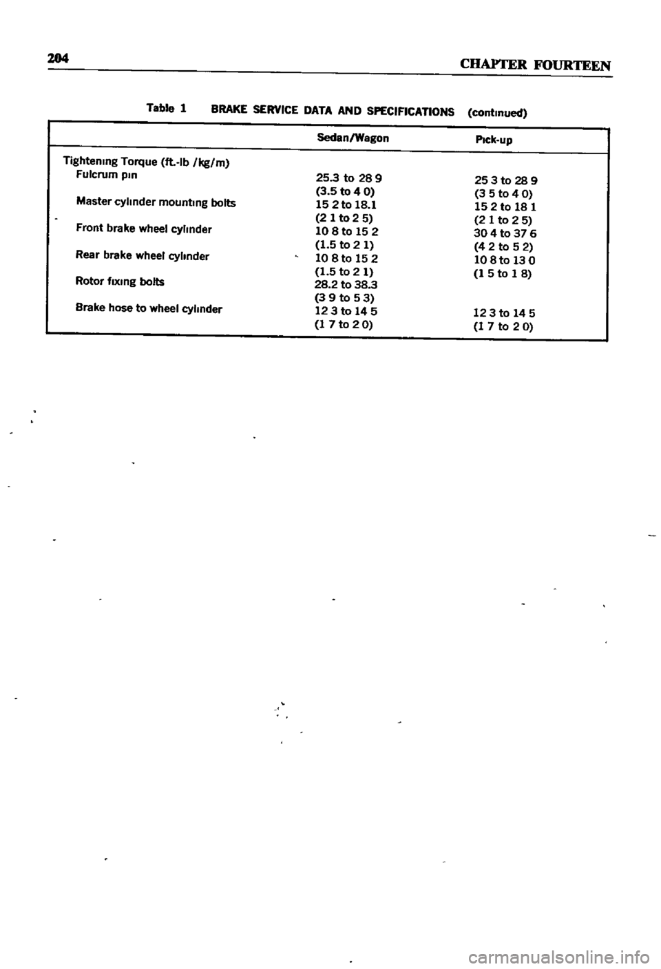
204
CHAPTER
FOURTEEN
Table
1
BRAKE
SERVICE
DATA
AND
SPECIFICATIONS
continued
Sedan
Wagon
Pick
up
Tightening
Torque
ft
lb
Ikg
m
Fulcrum
pm
25
3
to
28
9
253to289
3
5
to
4
0
3
5
to
4
0
Master
cylinder
mounting
bolts
15
2
to
18
1
152
to
18
1
2
Ito
2
5
2
1
to
2
5
Front
brake
wheel
cylinder
108
to
152
30
4
to
37
6
1
5
to
2
1
4
2
to
5
2
Rear
brake
wheel
cylinder
10
8
to
15
2
10
8
to
13
0
1
5
to
2
1
1
5
to
1
8
Rotor
fixing
bolts
28
2
to
38
3
39to53
Brake
hose
to
wheel
cylinder
123
to
14
5
123
to
14
5
1
7
to
2
0
1
7
to
2
0
Page 241 of 252
INDEX
A
Inspection
and
repair
191
Air
cleaner
Pad
replacement
190
Exploded
views
63
64
Piston
seal
replacement
193
Removal
and
replacement
62
Reassembly
and
installation
193
Removal
190
Air
pump
40
Brakes
front
pick
up
Alternator
Brushes
104
Adjustment
201
Diode
103
Exploded
View
195
Disassembly
98
ServiCing
194
SpecdicatIons
194
203
204
Exploded
Views
41
99
Brakes
rear
pick
up
Inspection
and
repair
101
Adjustment
202
Output
checks
104
Exploded
View
195
Reassembly
104
Servicing
194
Removal
40
98
Brakes
rear
sedan
and
wagon
Rotor
102
Adjustment
202
Stator
102
Exploded
view
194
Axle
removal
pick
up
175
Inspection
and
repair
193
Reassembly
194
B
Removal
and
disassembly
193
Breaker
points
110
Ball
JOint
lower
sedan
and
wagon
174
Bumpers
Battery
Exploded
view
front
pick
up
223
Inspecllon
aiii
I
servicing
21
Exploded
View
front
sedan
and
wagon
224
SpeCific
gravity
21
Exploded
view
rear
sedan
230
Body
Exploded
view
rear
wagon
231
Body
Irlm
and
bumpers
223
224
Door
lock
and
regulator
225
C
Doors
225
Hood
lock
control
225
Camshaft
Seats
228
DeSCription
34
Tail
gate
228
Exploded
view
37
Trunk
hd
and
bumper
228
Inspection
48
Brake
pedal
Reassembly
54
Inspection
and
repair
187
Sprocket
53
Installation
188
Tlmmg
chain
57
Removal
187
Carburetor
Brakes
Cleaning
and
inspection
75
Adjustment
201
202
Dash
pot
adjustment
71
Bleeding
196
DesCription
37
69
Brake
pedal
187
Disassembly
71
Front
diSC
sedan
and
wagon
190
193
Exploded
Views
74
75
Front
drum
pick
up
194
Fuel
level
adjustment
69
Handbrake
197
201
Idhng
adjustment
69
Master
cyhnder
188
Interlock
valve
70
Rear
pick
up
194
Reassembly
76
Rear
sedan
and
wagon
193
Removal
40
71
SpeCifications
and
service
data
203
204
Sectional
view
69
Troubleshooting
16
Throttle
valve
70
Wheel
cyhnders
pIck
up
196
Charging
system
Brakes
front
diSC
sedan
and
wagon
Troubleshooting
12
Adjustment
201
Choke
and
accelerator
Disassembly
191
Disassembly
and
installation
82
Exploded
view
192
Exploded
view
83