1968 DATSUN 510 wheel bolts
[x] Cancel search: wheel boltsPage 22 of 252

TROUBLESHOOTING
17
of
tIre
loose
wheels
unproper
adjustment
or
wear
of
front
wheel
bearIngs
faulty
wheel
align
ment
or
wear
of
transverse
lInk
and
tension
rod
bushings
Inspect
all
parts
carefully
for
wear
or
damage
Replace
or
replUI
parts
as
required
2
Shock
transmltled
through
steering
wheel
This
is
usually
most
noticeable
when
traveling
over
bad
roads
at
relatively
high
speeds
Causes
Include
damage
to
the
idler
ann
insuffiCient
tIghtening
of
steenng
gear
box
wear
of
the
steer
Ing
linkage
and
wear
of
the
suspension
ball
joint
Inspect
all
parts
for
wear
or
damage
Refer
to
Chapter
ThIrteen
for
service
or
repair
you
can
perform
and
for
procedures
which
should
be
referred
to
your
deal
r
3
Shlmmymg
This
is
usually
most
noticeable
when
a
specIfic
speed
IS
attained
and
will
normally
repeat
at
that
speed
Causes
are
generally
unbalanced
wheels
unproper
adjustment
of
steenng
gear
insuffi
cient
backlash
malfunction
of
the
shock
ab
sorbers
or
loose
bolts
for
the
strut
mountIng
Reparr
or
replace
defective
parts
as
required
Refer
to
Chapter
Thirteen
4
Wandermg
of
car
m
one
dlrectlOnl
This
problem
can
be
caused
by
improper
air
pressure
loose
wheel
nuts
difference
in
tire
tread
wear
from
left
to
right
side
Incorrect
adjustment
of
wheel
bearings
defectIve
wheel
beanngs
collapsing
or
twistIng
of
front
spnng
or
Incorrect
wheel
alignment
Also
binding
of
the
brake
shoes
worn
bushings
in
the
transverse
link
or
the
tension
rod
and
deformation
of
s
enng
lInkage
and
suspension
link
can
cause
wander
Carefully
iuspect
all
parts
for
looseness
and
wear
and
re
place
or
repaIr
as
required
In
some
c
ases
a
de
fective
rear
suspension
may
also
cause
the
vehicle
to
wander
5
InstabIlity
Instability
can
be
caused
by
unproper
tIre
pres
sures
worn
bushings
in
the
transverse
link
and
tension
rod
mcorrect
wheel
alignment
worn
steenng
linkage
Incorrect
adjustment
of
steer
ing
gear
and
unbalanced
wheels
Inspect
all
parts
carefully
for
wear
and
damage
Adjust
repair
or
replace
as
required
6
Heavy
feelmg
m
steering
This
can
be
caused
by
improper
tIre
pressures
insuffiCient
or
contamInated
lubncant
in
gear
box
damage
or
insuffiCient
grease
In
suspeuslon
ball
Joint
damaged
or
badly
adjusted
wheel
bearIngs
worn
or
damaged
steermg
gear
dam
age
of
upper
strut
bearing
and
mterference
of
steenng
column
With
turn
signal
SWitch
Inspect
all
parts
carefully
for
wear
and
damage
Adjust
repair
or
replace
as
required
7
ExceSSIve
play
m
steermg
wheel
This
is
usually
caused
by
Incorrect
adjustment
of
the
steenng
gear
worn
bushings
in
the
steering
linkage
or
Idler
arm
mcorrect
adjustment
of
the
front
wheel
bearings
worn
bushIngs
in
the
trans
verse
lInk
and
tension
rod
Carefully
inspect
all
parts
for
wear
or
damage
Adjust
repair
or
re
place
as
reqUIred
TIRE
WEAR
ANALYSIS
Abnormal
tIre
wear
should
always
be
ana
lyzed
to
deternune
the
cause
The
most
common
are
Incorrect
tIre
pressure
improper
dnving
overloading
and
Incorrect
wheel
ahgDment
Figures
2A
through
2F
identify
wear
patterns
and
mdicate
likely
causes
Of
I
1
l
D
1
Undennflatlon
Worn
more
on
Sides
than
In
center
Page 43 of 252
38
CHAPTER
SIX
EMISSION
CONTROL
DEVICES
All
Datsuns
have
a
sealed
type
of
crankcase
emISSion
control
device
and
an
exhaust
emISsion
control
deVice
Models
sold
m
Cahfornla
smce
1970
also
have
an
evaporative
emisSion
control
deVice
An
rmportant
part
of
the
exhaust
control
device
is
the
air
pump
located
at
the
bottom
left
hand
side
of
the
engme
It
IS
dnven
by
a
belt
off
of
the
crankshaft
pulley
and
supphes
air
to
the
exhaust
system
In
1972
an
electric
blower
in
corporated
m
the
air
cleaner
replaced
the
mechanical
pumI
ENGINE
REMOVAL
Expenence
has
shown
It
IS
easier
to
remove
the
engine
and
the
transmission
as
a
smgle
UnIt
than
to
remove
the
engme
alone
Once
the
en
gine
and
transmiSSIon
are
out
of
the
vehIcle
the
tranSmIssion
can
be
detached
from
the
engme
To
remove
the
engme
transmISsion
proceed
as
follows
1
Scribe
ahgnment
marks
on
the
hood
around
the
hmges
ThIS
will
make
remstallatlon
eaSIer
2
Remove
the
two
bolts
that
secure
each
hInge
and
remove
the
hood
It
is
not
necessary
to
re
move
the
hood
support
from
the
engme
firewall
3
DISconnect
the
lower
radIator
hose
from
the
right
hand
SIde
of
the
engine
and
at
the
bottom
of
the
radIator
ThIS
will
pernnt
coolant
to
dram
from
the
engme
and
the
radIator
4
Remove
the
draIn
plugs
from
the
engine
pan
and
translIDSsIon
and
completely
dram
lubn
cants
Into
suitable
contamers
5
DISconnect
the
battery
cables
from
the
bat
tery
loosen
the
two
hold
down
clamps
and
re
move
the
battery
NOTE
The
location
and
number
of
hoses
to
be
removed
from
the
air
cleaner
varies
from
model
to
model
It
IS
normally
easier
to
remove
the
hoses
from
the
sources
rather
than
try
to
dISconnect
them
from
yndemeath
the
air
cleaner
The
1972
model
Will
requlre
dlsconnectlOn
of
the
electrica1
cirCUit
In
the
air
cleaner
system
wing
nut
from
the
top
of
the
air
cleaner
and
remove
the
aIr
cleaner
7
DIsconnect
the
upper
radiator
hose
from
the
radiator
and
the
thermostat
housmg
Remove
the
hose
8
Disconnect
the
two
heater
hoses
from
the
nght
hand
side
of
the
engme
TIe
these
bac
so
they
won
t
interfere
with
removal
of
the
engme
9
Remove
the
radIator
grille
by
unscrewing
all
mountmg
screws
10
Remove
the
four
mounting
screws
holding
the
fan
shield
to
the
backside
of
the
radiator
11
Remove
the
four
mountmg
bolts
holdIng
the
radiator
In
place
In
automatic
tranSmISsion
models
dISconnect
the
two
transnnsslOn
oIl
cooler
lInes
from
the
bottom
of
the
radiator
Pull
the
radiator
straight
up
to
remove
Remove
the
fan
shield
12
Loosen
the
adjustment
and
mounting
bolts
from
the
retamIng
brackets
on
the
alternator
and
air
pump
If
so
eqwpped
The
alternator
is
lo
cated
at
the
bottom
nght
hand
Side
of
the
engme
and
the
air
pump
on
the
lower
left
hand
Side
13
Loosen
tenSIon
on
the
two
dnve
belts
re
move
the
belts
from
the
alternator
and
air
pump
and
then
from
the
fan
pulleys
14
Remove
the
bolts
holdIng
the
fan
and
pulley
to
the
water
pump
assembly
and
remove
the
fan
and
pulley
15
DISconnect
the
fuel
hne
from
the
fuel
pump
16
DIsco
ect
accelerator
control
linkage
and
choke
WIre
at
the
carburetor
17
Disconnect
the
wiring
from
the
starter
motor
alternator
Ignition
coIl
oIl
pressure
switch
and
temperature
transmItting
unit
NOTE
The
following
steps
are
per
formed
from
under
the
car
lack
up
the
front
of
the
car
and
position
stands
under
the
front
support
points
to
proVide
working
room
under
the
vehicle
WARNING
Never
climb
under
a
vehicle
that
is
supported
by
the
lack
only
If
stands
are
not
avflllable
sturdy
wooden
blocks
can
be
U3ed
6
Disconnect
all
hoses
that
lead
to
the
air
cleaner
remove
two
bolts
that
hold
the
air
cleaner
to
its
mountmg
bracket
unscrew
the
18
Remove
two
bolts
holdIng
the
clutch
operat
Ing
cylInder
to
the
flywheel
hOUSIng
shown
m
Page 45 of 252
40
CHAPTER
SIX
be
removed
Hoist
the
engme
off
Its
mounts
and
adjust
the
cham
or
cable
to
tIlt
the
engme
as
shown
in
the
illustration
ContInue
to
raIse
gradually
31
Once
the
engine
and
transmission
are
clear
of
the
vehIcle
lower
them
to
a
swtable
support
or
stand
and
dIsconnect
the
hOISt
32
The
transmISSIon
can
now
be
freed
by
re
movmg
the
bolts
holdIng
the
clutch
assembly
to
the
flywheel
housing
and
movmg
the
clutch
assembly
back
to
dIsengage
the
dnve
shaft
splmes
33
Witlltlie
engIne
removed
carefiillyinspect
the
mountIng
Insulators
for
SIgnS
of
damage
or
detenoratIon
Replace
them
1f
necessary
ENGINE
DISASSEMBLY
ThIS
sectIon
covers
dIsassembly
of
the
engine
once
It
has
been
removed
from
the
vehIcle
All
steps
would
be
followed
for
a
complete
engme
overhaul
But
smce
many
of
the
procedures
can
be
done
WIthout
removing
the
engIne
from
the
velucle
a
complete
course
of
actIon
should
be
decided
on
before
needless
removal
and
ms
assembly
Mount
the
engme
on
a
stand
or
other
sUItable
work
surface
before
msassembly
Thoroughly
clean
the
extenor
WIth
steam
or
solvent
CAUTION
Remove
the
alternator
starter
motor
carburetor
and
dIStributor
from
the
engine
before
cleaning
to
prevent
damage
Once
clean
mspect
the
engme
for
SIgnS
of
damage
or
mlssmg
parts
cracks
or
accumulated
rust
on
the
block
especIally
around
the
soft
plugs
cracks
In
the
clutch
housing
and
dents
or
cracks
In
the
oil
pan
DISassemble
as
follows
Alternator
Removal
1
Figure
14
shows
the
positIon
of
the
alternator
on
the
engme
and
a
VIew
of
the
alternator
mountIng
parts
Remove
the
two
bolts
lock
washers
and
shmls
holding
the
alternator
to
the
adjustIng
bar
and
the
adjustIng
bar
to
the
engme
block
2
Remove
the
two
bolts
and
lockwashers
hold
ing
the
alternator
to
lower
mounting
bracket
3
Remove
the
alternator
and
mountmg
brack
ets
Starter
Motor
Removal
1
Remove
two
mountIng
bolts
and
lockwashers
holdmg
starter
motor
to
clutch
housmg
2
Pull
starter
assembly
toward
front
of
engme
and
remove
Distributor
Removal
1
Scnbe
ahgnment
marks
on
the
mstrlbutor
shaft
tl
ie
ihsthDutor
mountmg
oracket
anihlfe
front
cover
so
that
the
dIStnbutor
can
be
re
placed
accurately
later
2
Remove
two
bolts
and
lockwashers
holdIng
the
dlstnbutor
mountmg
housmg
to
the
front
cover
3
Pull
up
on
the
dlstnbutor
and
remove
it
as
a
unit
Carburetor
Removal
1
Remove
the
four
nuts
and
lockwashers
join
mg
the
carburetor
and
mtake
manifold
then
remove
carburetor
Oil
Pump
Removal
1
Remove
the
four
mountIng
bolts
and
lock
washers
2
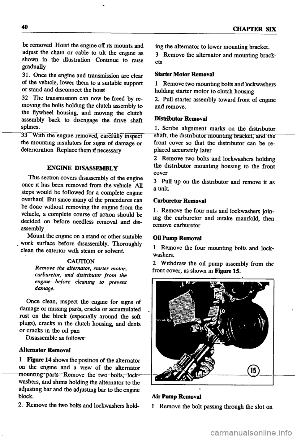
WIthdraw
the
011
pump
assembly
from
tht
front
cover
as
shown
m
Figure
15
@
Air
Pump
Removal
1
Remove
the
bolt
passmg
through
the
slot
on
Page 49 of 252
44
CHAPTER
SIX
@
@
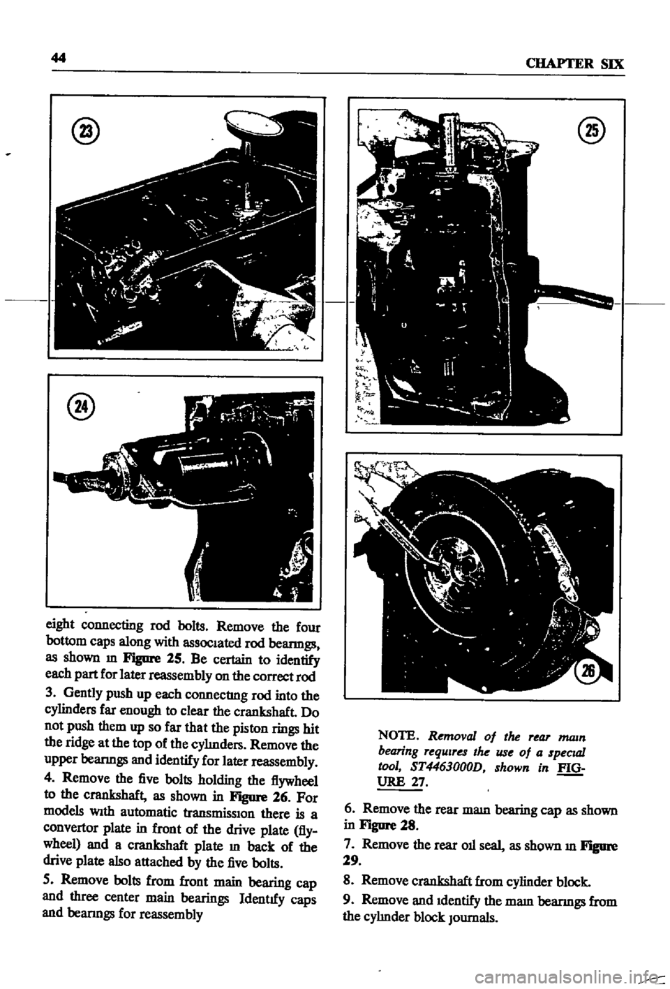
eight
connecting
rod
bolts
Remove
the
four
bottom
caps
along
with
assoc1ated
rod
beanngs
as
shown
m
Figure
25
Be
certain
to
identify
each
part
for
later
reassembly
on
the
correct
rod
3
Gently
push
up
each
connecting
rod
into
the
cylinders
far
enough
to
clear
the
crankshaft
Do
not
push
them
up
so
far
that
the
piston
rings
hit
the
ridge
at
the
top
of
the
cyImders
Remove
the
upper
beanngs
and
identify
for
later
reassembly
4
Remove
the
five
bolts
holding
the
flywheel
to
the
crankshaft
as
shown
in
Figure
26
For
models
Wlth
automatic
transmisslOn
there
is
a
convertor
plate
in
front
of
the
drive
plate
fly
wheel
and
a
crankshaft
plate
m
back
of
the
drive
plate
also
attached
by
the
five
bolts
5
Remove
bolts
from
front
main
bearing
cap
and
three
center
main
bearings
Identtfy
caps
and
beanngs
for
reassembly
@
NOTE
Removal
of
the
rear
mam
bearing
requires
the
use
of
a
specuzl
tool
ST4463000D
shown
in
f
Q
URE
27
6
Remove
the
rear
mam
bearing
cap
as
shown
in
Figure
28
7
Remove
the
rear
011
seal
as
shown
m
Figure
29
8
Remove
crankshaft
from
cylinder
block
9
Remove
and
1dentify
the
mam
beanngs
from
the
cyhnder
block
JOurnals
Page 58 of 252
ENGINE
53
the
mam
beanng
cap
and
the
cyhnder
block
beanng
recess
and
tighten
the
cap
bolts
to
the
proper
torque
WIth
a
torque
wrench
Tig
temng
torque
Main
bearings
506
to
57
8
It
Ib
70to80kg
m
195
to
23
9
It
Ib
27
to3
3
kg
m
Rod
beanngs
9
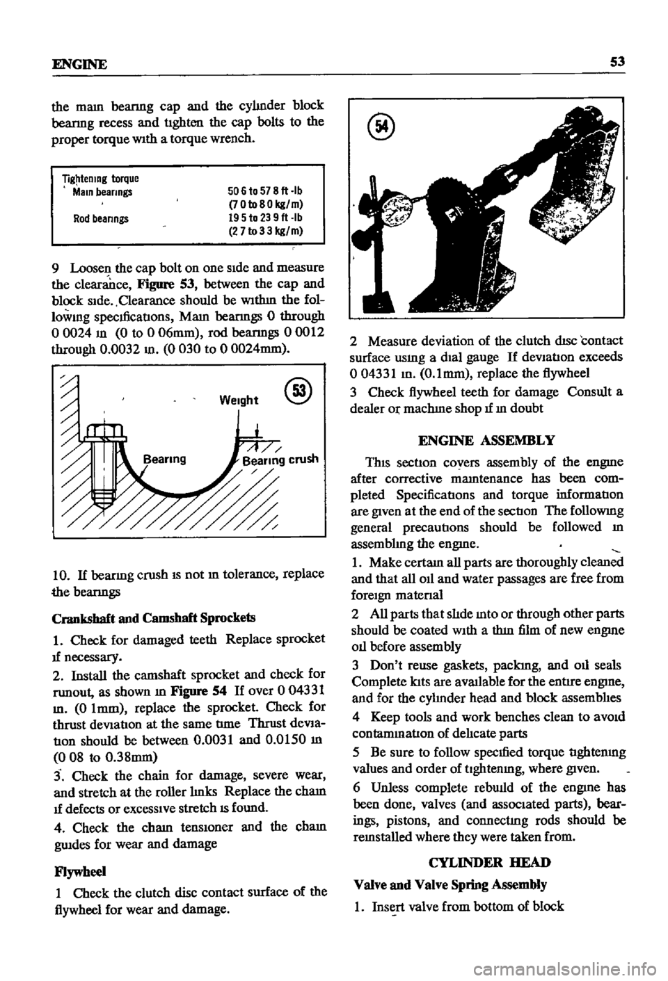
Loosen
the
cap
bolt
on
one
Side
and
measure
the
clearance
Figure
53
between
the
cap
and
block
Side
Clearance
should
be
WIthm
the
fol
lowmg
specmcatIons
Mam
beanngs
0
through
o
0024
m
0
to
0
06mm
rod
beanngs
00012
through
0
0032
m
0
030
to
0
0024mm
Weight
@
10
If
beanng
crush
IS
not
m
tolerance
replace
the
beanngs
Crankshaft
and
Camshaft
Sprockets
1
Check
for
damaged
teeth
Replace
sprocket
1f
necessary
2
Install
the
camshaft
sprocket
and
check
for
runout
as
shown
m
Figure
54
If
over
0
04331
m
0
Imm
replace
the
sprocket
Check
for
thrust
deViation
at
the
same
tIme
Thrust
deVia
tIOn
should
be
between
0
0031
and
0
0150
m
008
to
0
38mm
3
Check
the
chain
for
damage
severe
wear
and
stretch
at
the
roller
hnks
Replace
the
cham
1f
defects
or
exceSSIve
stretch
IS
found
4
Check
the
cham
tenslOner
and
the
cham
gwdes
for
wear
and
damage
Flywheel
1
Check
the
clutch
disc
contact
surface
of
the
flywheel
for
wear
and
damage
@
2
Measure
deviation
of
the
clutch
disc
contact
surface
usmg
a
dial
gauge
If
deVIation
exceeds
004331
m
O
lmm
replace
the
flywheel
3
Check
flywheel
teeth
for
damage
Consult
a
dealer
Or
machIne
shop
1f
m
doubt
ENGINE
ASSEMBLY
This
section
covers
assembly
of
the
engme
after
corrective
mamtenance
has
been
com
pleted
SpecificatIons
and
torque
informatIon
are
given
at
the
end
of
the
sectIon
The
followmg
general
precautions
should
be
followed
m
assembhng
the
engme
1
Make
certam
all
parts
are
thoroughly
clean
and
that
all
011
and
water
passages
are
free
from
foreign
matenal
2
All
parts
that
slIde
mto
or
through
other
parts
should
be
coated
With
a
thm
film
of
new
engme
011
before
assembly
3
Don
t
reuse
gaskets
packIng
and
011
seals
Complete
lats
are
aVlUlable
for
the
entire
engme
and
for
the
cyhnder
head
and
block
assemblIes
4
Keep
tools
and
work
benches
clean
to
aVOid
contammatlon
of
delIcate
parts
5
Be
sure
to
follow
specmed
torque
tIghtenmg
values
and
order
of
tlghtenmg
where
given
6
Unless
complete
rebwld
of
the
engme
has
been
done
valves
and
associated
parts
bear
ings
pistons
and
connectIng
rods
should
be
remstalled
where
they
were
taken
from
CYLINDER
HEAD
Valve
and
Valve
Spring
Assembly
1
Insert
valve
from
bottom
of
block
Page 60 of 252

ENGINE
55
Cylinder
Block
Assembly
1
PositIon
all
crankshaft
parts
on
a
work
bench
ThIS
mcludes
the
crankshaft
main
beanngs
rear
011
seal
woodruff
keys
crankshaft
gear
011
pump
gear
011
thrower
bolts
and
bearing
caps
Figure
57
shows
the
arrangement
@
2
Insert
maIO
beanngs
mto
appropnate
cy1m
der
block
holders
NOTE
The
center
No
3
beanng
IS
the
only
flanged
type
of
thrust
bear
Ing
Bearings
No
2
and
No
4
are
Identical
No
1
and
No
5
Jaring
ap
pear
identical
but
No
1
as
an
011
hole
All
bearings
except
No
1
are
Interchangeable
as
to
upper
and
lower
half
3
LIghtly
lubncate
the
crankshaft
and
beanng
matmg
surfaces
then
mstall
beanngs
10
mam
beanng
caps
4
Install
the
crankshaft
5
Install
mam
beanng
caps
over
crankshaft
msert
mam
cap
bolts
and
tighten
hghtly
The
mam
beanng
caps
have
an
arrow
marked
on
each
one
These
must
pomt
to
the
front
of
the
engme
6
Gently
move
the
crankshaft
10
an
aXIal
drrec
don
toward
the
front
of
the
engme
to
venfy
that
the
mam
beanng
caps
are
properly
alIgned
and
seated
7
Use
a
torque
wrench
to
tighten
the
cap
bolts
to
the
hmlts
speCIfied
The
t1ghtenmg
operatIon
should
be
done
gradually
10
three
or
four
sep
arate
stages
starting
10
the
center
and
workmg
outward
to
each
end
8
Rotate
the
crankshaft
to
make
certain
it
isn
t
bmding
9
Use
a
feeler
gauge
to
check
the
end
play
at
the
center
No
3
beanng
Figure
58
10
Install
the
SIde
oll
seals
into
the
rear
mam
cap
and
cy1mder
block
as
shown
10
Figure
59
@
11
Install
the
rear
011
seal
WIth
Datsun
tool
ST49370000
or
equIvalent
12
Install
the
rear
end
plate
13
Install
the
flywheel
WIth
proper
bolts
and
lock
washers
and
torque
as
specified
Page 64 of 252

ENGINE
59
2
Coat
the
pan
gasket
on
both
sides
With
gasket
compound
and
attach
the
oil
pan
to
the
cyhnder
block
Torque
as
specIfied
Manifold
and
Carburetor
Installation
1
Install
the
mtake
and
exhaust
manIfolds
WIth
associated
gasket
to
the
cylmder
head
2
Mount
the
carburetor
and
gasket
to
the
mtake
manIfold
2
Adjust
all
mtake
and
exhaust
valves
to
the
specIfied
clearance
for
a
cold
engme
Clutch
Assembly
Installation
CAUTION
Take
extreme
care
not
to
get
grease
or
011
on
the
clutch
or
flywheel
frlc
hon
contact
surfaces
1
Place
the
clutch
disc
assembly
on
the
flywheel
With
the
longer
chamfered
splmed
end
of
the
dISC
toward
the
transmISSion
2
Visually
align
or
use
a
dummy
splmed
dnve
shaft
to
ahgn
the
diSC
assembly
With
the
flywheel
pilot
beanng
3
Install
and
tighten
the
SIX
bolts
holdmg
the
clutch
cover
assembly
to
the
flywheel
Tighten
the
bolts
a
turn
each
tune
by
diagonal
pattern
until
they
are
tight
Tlghtenmg
torque
should
be
174
to
188ft
lbs
24
to
2
6
kg
m
NOTE
There
are
two
dowels
on
the
flywheel
to
locate
the
clutch
cover
4
Remove
dummy
shaft
If
used
after
the
above
bolts
are
fully
tightened
5
Refit
the
release
bearing
and
translI11Ssion
case
Miscellaneous
Installation
1
Connect
the
fuel
hose
on
the
front
part
of
the
engme
to
the
fuel
pump
and
to
the
carburetor
2
Gap
the
spark
plugs
and
mstall
them
usmg
new
gaskets
3
Coat
the
rocker
arm
cover
gasket
With
sealer
and
position
It
on
the
cylmder
head
4
Install
the
rocker
arm
cover
and
tighten
the
two
thumb
screws
that
hold
it
m
place
5
Install
distrIbutor
makmg
certam
that
the
notch
on
the
distributor
shaft
assembly
mates
With
the
drive
spmdle
Ahgn
the
location
marks
made
dunng
disassembly
so
that
the
distrIbutor
is
positioned
as
before
6
Install
and
tighten
the
bolts
which
hold
the
dIStributor
to
the
front
cover
7
Install
pomts
condenser
and
rotor
8
Replace
distrIbutor
cap
and
attach
spark
plug
Wires
m
the
correct
sequence
Make
certain
that
all
wires
are
firmly
seated
m
the
distrIbutor
cap
and
attached
securely
to
the
spark
plugs
9
HOISt
the
engme
assembly
from
the
work
stand
10
Install
the
alternator
bracket
alternator
and
engme
mounts
to
the
block
11
Install
the
IgnItIon
coil
oil
filter
oil
pressure
SWitch
dipstick
and
water
drain
plug
12
Connect
the
vacuum
Ime
between
the
dis
trIbutor
and
carburetor
13
Connect
the
transIDlSSlOn
to
the
engine
prior
to
mstallatIon
m
the
vehicle
Engine
Installation
Installation
is
the
reverse
of
the
procedures
followed
m
removal
Be
certaIn
thatlall
battery
connections
are
made
that
water
hoses
are
se
cured
wmng
IS
connected
properly
and
that
all
required
bolts
and
mounts
are
mstalled
and
tightened
Replace
the
radiator
fan
belts
and
radiator
shroud
Fill
the
engme
With
the
proper
grade
of
oil
and
the
radiator
With
recommended
coolant
Install
the
hood
to
the
hInges
according
to
the
marks
made
dUrIng
removal
SERVICE
DATA
AND
SPECIFICATIONS
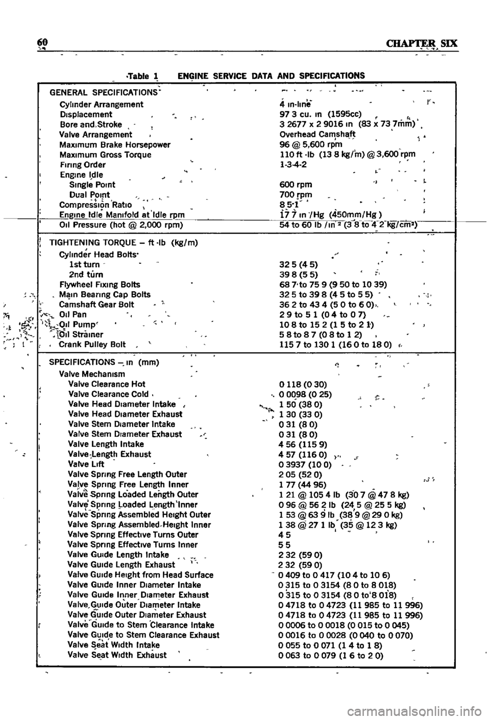
Table
1
covers
servIce
data
and
engme
Speci
fications
Page 65 of 252
60
SIX
Table
1
ENGINE
SERVICE
DATA
AND
SPECIFICATIONS
GENERAL
SPECIFICATIONS
Cylinder
Arrangement
DIsplacement
Bore
and
Stroke
Valve
Arrangement
MaxImum
Brake
Horsepower
MaxImum
Gross
Torque
Firing
Order
Engme
dle
Smgle
POint
Dual
Pomt
CompressIon
RatIo
Engme
Idle
Mamfold
at
Idle
rpm
011
Pressure
hot
@
2
000
rpm
i
TIGHTENING
TORQUE
ft
Ib
kg
m
Cylinder
Head
Bolts
1st
turn
2nd
turn
Flywheel
Flxmg
Bolts
M
In
Beanng
Cap
Bolts
Camshaft
Gear
Bolt
I
011
Pan
1
1
fF
I
011
Pump
QII
Stramer
F
I
Crank
Pulley
Bolt
SPECIFICATIONS
In
mm
Valve
Mechamsm
Valve
Clearance
Hot
Valve
Clearance
Cold
Valve
Head
DIameter
Intake
Valve
Head
DIameter
Exhaust
Valve
Stem
DIameter
Intake
Valve
Stem
DIameter
Exhaust
Valve
Length
Intake
Valve
Length
Exhaust
Valve
LIft
Valve
Spring
Free
Length
Outer
Valve
Sprmg
Free
Length
Inner
Vaiv
Spnng
Loaded
Length
Outer
Valve
Spring
Loaded
Length
Inner
Valve
Sprmg
Assembllld
HeIght
Outer
Valve
Spnng
Assembled
Helght
Inner
Valve
Spnng
Effective
Turns
Outer
Valve
Sprmg
EffectIve
Turns
Inner
Valve
GUIde
Length
Intake
Valve
GUIde
Length
Exhaust
Valve
GUIde
HeIght
from
Head
Surface
Valve
GUIde
Inner
DIameter
Intake
Valve
GUIde
Inner
DIameter
Exhaust
Va
Ive
GUIde
Outer
Dlam
eter
Intake
Valve
GUIde
Outer
DIameter
Exhaust
Valve
GUIde
to
Stem
Clearance
Intake
Valve
GUIde
to
Stem
Clearance
Exhaust
Valve
eat
W
dth
Intake
Valve
SEtat
WIdth
Exhaust
4
m
Ilnil
97
3
cu
m
1595cc
3
2677
x
2
9016
In
83
x
73
7mm
Overhead
Camshaft
96
@
5
600
rpm
110
ft
Ib
13
8
kg
m
@
3
600
rpm
1
3
4
2
r
600
rpm
700
pm
85
1
i7
7
In
Hg
450mm
Hg
54
to
60
Ib
m
2
3
8
tQ
4
2
Iig
cm
325
4
5
39
8
5
5
68
No
75
9
9
50
to
1039
325
to
39
8
4
5
to
5
5
362
to
43
4
50
to
60
2
9
to
5
1
0
4
to
0
7
108
to
15
2
1
5
to
2
1
58t087
08to
12
1157
to
130
1
160
to
180
o
118
0
30
o
0C
98
0
25
1
50
38
0
1
30
33
0
031
80
031
80
456
1159
4
57
116
O
03937
100
2
05
52
0
1
77
44
96
1
21
@
1054
Ib
3
07
@
47
8
kg
o
96
@
56
Ib
24
5
@
25
5
kg
1
53
@
63
9
Ib
38
9
@
29
0
kg
1
38
@
27
1
Ib
35
@
123
kg
45
I
55
2
32
59
0
2
32
59
0
0409
to
0
417
104
to
106
0315
to
03154
80
to
8018
0315
to
03154
80
to
8
Oi8
04718
to
04723
11
985
to
11
996
04718
to
04723
11
985
to
11
996
00006
to
00018
0
015
to
0
045
00016
to
00028
0040
to
0070
o
055
to
0
071
1
4
to
1
8
0063
to
0079
1
6
to
20