1968 DATSUN 510 fuel tank removal
[x] Cancel search: fuel tank removalPage 4 of 252
II
CHAPTER
SIX
ENGINE
Cylmder
block
Crankshaft
PistOns
and
connectmg
rods
Cyhnder
head
Camshaft
Valve
mechamsm
Camshaft
dnve
Mamfolds
011
pump
Fuel
pump
Carburetor
Emission
control
devIces
Engme
removal
Engme
dISassembly
Pistons
and
connectmg
rods
Cyhnder
head
Engme
mspectIon
and
replllr
Engme
reassembly
Service
data
and
speCifications
CHAPTER
SEVEN
FUEL
SYSTEM
Air
cleaner
Fuel
strlllner
Fuel
pump
Carburetor
Fuel
tank
1
CHAPTER
EIGHT
COOLING
SYSTEM
DescnptIon
Water
pump
Fan
clutch
Thermostat
Radiator
CHAPTER
NINE
ENGINE
ELECTRICAL
SYSTEM
Starter
Overrunmng
clutch
assembly
ChargIng
ClrcUlt
Alternator
Alternator
output
Voltage
regulator
DIstrIbutor
Condenser
Igrntlon
cod
SpeCifications
Spark
plugs
CHAPTER
TEN
EMISSION
CONTROL
SYSTEM
Exhaust
emiSSIOn
control
Crankcase
emission
control
Air
mJectlon
system
Engme
modifications
Evaporative
emiSSion
control
Exhaust
system
CHAPTER
ELEVEN
CLUTCH
TRANSMISSION
AND
DRIVESHAFT
Clutch
TransmissIon
Master
cyhnder
TransmissIon
data
and
speCIfications
Operating
cyhnder
Dnveshaft
Withdrawal
lever
adjustment
Dnveshaft
data
and
speCIfications
Clutch
system
bleedmg
Automatic
transmIssIon
checks
Clutch
data
and
speCIfications
31
62
84
91
114
127
Page 67 of 252
CHAPTER
SEVEN
FUEL
SYSTEM
The
fuel
system
mcludes
the
fuel
tank
straIner
pump
carburetor
arr
cleaner
and
necessary
lines
Inspect
components
for
leaks
and
deterioratIOn
whenever
mamtenance
is
done
The
fuel
stramer
should
be
mspected
peri
odIcally
and
cleaned
AIR
CLEANER
The
au
filter
element
is
viscous
paper
and
does
not
require
cleanmg
Replace
It
every
24
000
mlles
or
more
frequently
under
harsh
condItIons
Several
mInor
differences
exist
between
vehicles
dependmg
on
the
type
of
emisSIOn
con
trol
device
used
Figure
1
shows
location
of
the
air
cleaner
on
the
engme
and
parts
compnsing
the
cleaner
system
on
model
years
through
1969
Figure
2
shows
the
changes
for
1970
and
later
Warm
air
is
supplIed
to
the
air
cleaner
from
the
exhaust
mamfold
to
prevent
carburetor
Icmg
AIR
CLEANER
REMOVAL
AND
REPLACEMENT
1
Unthread
the
WIng
nut
atop
the
cleaner
assembly
2
Remove
the
two
bolts
holdIng
the
air
cleaner
to
the
support
3
Disconnect
the
aIr
cleaner
duct
from
the
base
of
the
cleaner
intake
throat
4
LIft
off
the
aIr
cleaner
body
and
remove
the
aIr
filter
as
shown
m
Figure
3
To
remove
the
arr
cleaner
proceed
as
follows
1
Perform
steps
1
through
4
above
2
Unscrew
the
band
bolt
at
the
base
of
the
air
cleaner
3
DIsconnect
all
hoses
leadmg
to
the
air
cleaner
4
Pull
up
on
the
body
of
the
air
cleaner
and
remove
from
carburetor
5
Except
for
the
au
filter
element
thoroughly
clean
all
parts
6
Reverse
the
steps
above
for
reassembly
FUEL
STRAINER
The
fuel
stramer
IS
located
on
the
nght
hand
side
of
the
engme
compartment
Figure
4
shows
the
fuel
stratner
hoses
clamps
and
the
mount
Ing
clIp
that
holds
the
fuel
stramer
In
place
The
fuel
stramer
IS
of
the
cartrIdge
type
and
uses
a
fiber
mat
and
nylon
as
strainer
elements
The
fuel
stramer
should
be
mspected
frequently
for
foreIgn
material
and
replaced
at
least
every
24
000
rmles
1
DIsconnect
the
inlet
and
outlet
hoses
from
the
fuel
stratner
Make
certatn
that
the
mlet
hose
bottom
IS
not
permItted
to
fall
below
the
level
of
the
fuel
tank
or
leakage
wIll
occur
Page 73 of 252
68
CHAPTER
SEVEN
Capacity
Test
Perform
the
capacity
test
only
when
the
statIc
pressiue
test
IS
withm
acceptable
lirmts
1
D
sconnect
the
fuellme
at
the
carburetor
2
Place
a
sUItable
container
at
the
end
of
the
fuellme
3
St
lrt
the
engm
and
run
at
OOO
rpm
4
The
fuel
pump
should
delIver
fuel
into
the
co
ntainer
at
a
rate
slightly
over
two
pints
per
minute
If
no
gasolme
or
only
a
lIttle
appears
the
fuel
lme
is
clogged
or
thefuel
pump
defectIve
Bef
removmg
the
fuel
pump
remove
the
gas
tank
filler
cap
dtsconnect
the
mlet
and
outlet
fuel
lmes
and
qlow
through
them
With
compressed
air
to
make
certam
they
are
clear
Reconnect
the
fuellmes
and
retest
the
flow
If
stIll
insufficient
the
fuel
p
mp
requires
servicmg
or
replacement
Fuel
Punip
Removal
and
Disassembly
1
Unscrew
the
two
mountIng
nuts
hOldmg
fuel
pump
to
the
cylmder
head
2
Disconnect
the
inlet
and
outlet
lines
3
Remove
the
fuel
pump
from
the
cylmder
head
4
Place
the
pump
on
a
work
bench
and
remove
the
screws
jommg
the
upper
and
lower
bodIes
5
Remove
the
cap
and
gasket
by
removing
the
cap
screws
6
Unscrew
the
elbow
and
connector
7
Remove
the
valve
retamer
by
unscrewmg
the
two
valve
retamer
screws
The
two
valves
are
then
easily
removed
8
To
remove
the
dIaphragm
spring
lower
body
seal
washer
and
lower
body
seal
from
the
lower
body
press
the
diaphragm
down
Wh1le
domg
thIS
cant
the
dIaphragm
so
that
the
rectangular
part
m
the
lower
end
of
the
pull
rod
unhooks
from
the
rocker
arm
lmk
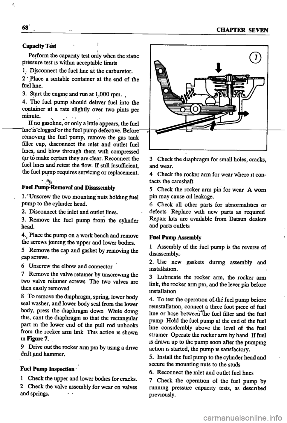
ThIS
action
IS
shown
mFigure7
9
Drive
out
the
rocker
arm
pm
by
usmg
a
dnve
dnft
nd
hammer
Fuel
Pump
Inspection
1
Check
the
upper
and
lower
bodIes
for
cracks
2
Check
the
valve
assembly
for
wear
on
valves
and
springs
CD
3
Check
the
diaphragm
for
small
holes
cracks
and
wear
4
Check
the
rocker
arm
for
wear
where
It
con
tacts
the
camshaft
5
Check
the
rocker
arm
pin
for
wear
A
worn
pin
may
cause
011
leakage
6
Check
all
other
parts
for
abnormalItIes
or
defects
Replace
With
new
parts
as
reqUlred
Reparr
kIts
are
available
from
Datsun
dealers
and
parts
outlets
Fuel
Pump
Assembly
1
Assembly
of
the
fuel
pump
is
the
reverse
of
dlsassembly
2
Use
new
gaskets
durmg
assembly
and
mstanatIon
3
Lubncate
the
rocker
arm
the
rocker
arm
link
the
rocker
arm
pm
and
the
lever
pin
before
mstallatIon
4
To
test
the
operatIon
ohhe
fuel
pump
before
remstallatlOn
connect
a
three
foot
pIece
of
fuel
lme
or
hose
betweentbe
fuel
filter
and
the
fuel
pump
Hold
the
fuel
pump
at
the
end
of
the
fuel
lme
conSIderably
above
the
level
of
the
fuel
stramer
Operate
the
rocker
arm
by
hand
If
fuel
IS
drawn
up
to
the
pump
soon
after
the
pumpmg
actIon
IS
started
the
pump
IS
satIsfactory
5
Install
the
fuel
pump
to
the
cylmder
head
and
secure
the
mounting
nuts
to
the
studs
6
Reconnect
the
mlet
and
outlet
fuellmes
7
Check
the
operatIon
of
the
fuel
pump
by
runnmg
pressure
capaCIty
tests
as
descnbed
preVIously
Page 81 of 252
76
CHAPTER
SEVEN
Carburetor
Assembly
Assembly
is
the
reverse
of
dISassembly
Make
certam
all
gaskets
are
mounted
flat
Be
careful
not
to
use
force
In
assembly
Make
certam
that
all
Interlock
lInks
operate
smoothly
FUEL
TANK
Description
FIgures
15
16
17
and
18
are
exploded
views
of
the
fuel
tanks
used
on
the
sedan
and
wagons
Figure
15
IS
for
sedans
through
model
year
1969
Figure
16
applIes
to
sedans
from
1970
With
evaporative
control
system
F
q
nre
17
shows
the
statIon
wagon
through
1969
Figure
18
applIes
to
the
statIon
wagon
WIth
evaporative
control
system
f
m
1970
The
fuel
tank
for
the
pIck
up
is
shown
m
Figure
19
A
fuel
return
system
from
the
carburetor
to
the
fuel
tank
keeps
fuel
from
becommg
over
heated
m
the
carburetor
float
chamber
When
the
normal
level
m
the
float
chamber
IS
exceeded
a
pressure
valve
opens
and
returns
the
excess
fuel
to
the
tank
Removal
Sedans
1
Remove
drain
plug
m
bottom
of
fuel
tank
and
drain
the
fuel
into
a
suitable
safe
contamer
2
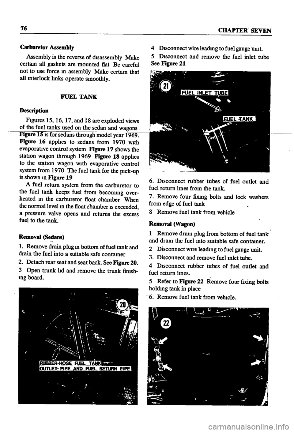
Detach
rear
seat
and
seat
back
See
Figure
20
3
Open
trunk
lId
and
remove
the
trunk
finISh
mg
board
4
DIsconnect
wire
leadmg
to
fuel
gauge
umt
5
DIsconnect
and
remove
the
fuel
inlet
tube
See
Figure
21
6
DIsconnect
rubber
tubes
of
fuel
outlet
and
fuel
return
lInes
from
the
tank
7
Remove
four
fixmg
bolts
and
lock
washers
from
edge
of
fuel
tank
8
Remove
fuel
tank
from
vehicle
Removal
Wagon
1
Remove
draIn
plug
from
bottom
of
fuel
tank
and
dram
the
fuel
mto
swtable
safe
contatner
2
Disconnect
WIre
leadIng
to
fuel
gauge
unit
3
Disconnect
and
remove
fuel
mlet
tube
4
DISconnect
rubber
tubes
of
fuel
outlet
and
fuel
return
lInes
5
Refer
to
Figure
22
Remove
four
fixing
bolts
holdmg
tank
in
place
6
Remove
fuel
tank
from
veh1c1e
Page 87 of 252
82
CHAPTER
SEVEN
Removal
Pick
up
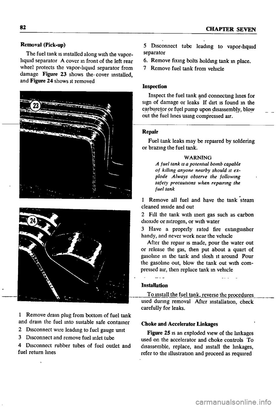
The
fuel
tank
IS
mstalled
along
With
the
vapor
liqUid
separator
A
cover
m
front
of
the
left
rear
wheel
protects
the
vapor
lIqUid
separator
from
damage
Figure
23
shows
the
cover
mstalled
and
Figure
24
shows
It
removed
I
Remove
dram
plug
from
bottom
of
fuel
tank
and
dram
the
fuel
mto
sUitable
safe
contamer
2
Disconnect
wire
leadmg
to
fuel
gauge
unIt
3
Disconnect
and
remove
fuel
Inlet
tube
4
Disconnect
rubber
tubes
of
fuel
outlet
and
fuel
return
lInes
5
Disconnect
tube
leadmg
to
vapor
liqUid
separator
6
Remove
fixmg
bolts
holdmg
tank
In
place
7
Remove
fuel
tank
from
vehIcle
Inspection
Inspect
the
fuel
tank
d
connectIng
lInes
for
SIgn
of
damage
or
leaks
If
dIrt
IS
found
In
the
carbl
relor
r
fuel
pump
upon
dlsassemb
y
blo
out
the
fuel
lines
usmg
compressed
air
Repair
Fuel
tank
leaks
may
be
repaired
by
soldering
or
brazmg
the
fuel
tank
WARNING
A
fuel
tank
IS
a
potential
bomb
capable
of
klllmg
anyone
nearby
should
It
ex
plode
Always
observe
the
followmg
safety
precautions
when
repairing
the
fuel
tank
1
Remove
all
fuel
and
have
the
tank
steam
cleaned
InSIde
and
out
2
F1l1
the
tank
WIth
Inert
gas
such
as
carbon
diOXide
or
mtrogen
or
WIth
water
3
Have
a
properly
rated
fire
extIngUisher
handy
and
never
work
near
the
vehicle
After
the
repair
IS
made
pour
the
water
out
or
release
the
gas
then
put
about
a
quart
of
gasolme
In
the
tank
and
slosh
It
around
Pour
the
gasolme
out
blow
the
tank
out
WIth
com
pressed
aIr
then
replace
tank
In
vehIcle
Installation
To
mstall
the
f
iel
tank
reverse
the
p
rocedur
used
dUring
removal
After
InstallatIon
check
carefully
for
leaks
Choke
and
Accelerator
Linkages
Figure
25
IS
an
exploded
VIew
of
the
lInkages
used
on
the
accelerator
and
choke
controls
To
disassemble
replace
and
mstall
the
lInkages
refer
to
the
IllustratIon
and
proceed
as
reqUIred
Page 128 of 252
EMISSION
CONTROL
SYSTEM
123
7
If
the
pressure
does
not
meet
reqwrements
dISconnect
the
aIr
supply
hose
to
the
antI
backfire
valve
Clamp
a
plug
mto
the
hose
and
repeat
the
pressure
test
8
If
the
air
mJection
pump
does
not
meet
the
pressure
specIfication
It
should
be
replaced
NOTE
Repair
of
the
air
injection
pump
is
possible
but
have
the
lob
done
by
your
dealer
9
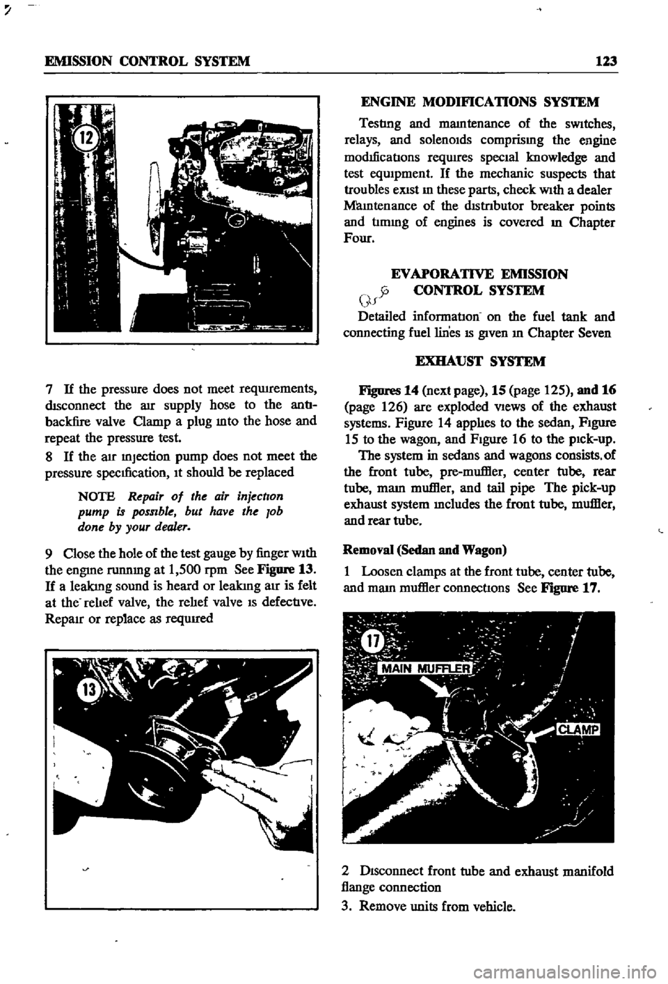
Close
the
hole
of
the
test
gauge
by
finger
With
the
engme
runnmg
at
1
500
rpm
See
Figure
13
If
a
leakIng
sound
is
heard
or
leakIng
air
is
felt
at
the
relIef
valve
the
relIef
valve
IS
defectIve
RepaIr
or
replace
as
reqUIred
ENGINE
MODIFICATIONS
SYSTEM
Testlng
and
mamtenance
of
the
sWitches
relays
and
solenOIds
comprismg
the
engine
modIficatIons
reqwres
SpecIal
knowledge
and
test
eqUIpment
If
the
mechanic
suspects
that
troubles
eXist
In
these
parts
check
With
a
dealer
Mamtenance
of
the
dIstrIbutor
breaker
points
and
tImmg
of
engines
is
covered
m
Chapter
Four
EVAPORATIVE
EMISSION
y
CONTROL
SYSTEM
f
Detailed
informatIon
on
the
fuel
tank
and
connecting
fuel
lines
IS
given
In
Chapter
Seven
EXHAUST
SYSTEM
Figures
14
next
page
15
page
125
and
16
page
126
are
exploded
VIews
of
the
exhaust
systems
Figure
14
applIes
to
the
sedan
FIgure
15
to
the
wagon
and
FIgure
16
to
the
pIck
up
The
system
in
sedans
and
wagons
consists
of
the
front
tube
pre
muffier
center
tube
rear
tube
mam
muffier
and
tail
pipe
The
pick
up
exhaust
system
mcludes
the
front
tube
muffier
and
rear
tube
Removal
Sedan
and
Wagon
1
Loosen
clamps
at
the
front
tube
center
tube
and
mam
muffier
connectIons
See
Figure
17
2
DIsconnect
front
tube
and
exhaust
manifold
flange
connection
3
Remove
units
from
vehicle
Page 243 of 252
INDEX
237
2
7
30
28
WIrIng
diagrams
WIrIng
harnesses
Electncal
system
engme
Alternator
Chargmg
ClfCUlt
Dlstnbutor
IgmtlOn
coIl
Spark
plugs
Starter
Voltage
regulator
Emission
control
crankcase
DescnptIon
General
mspectIon
SchematIc
vIew
VentIlatIOn
control
valve
EmIssIOn
control
exhaust
AIr
pump
AntI
backfire
valve
Check
valve
DescnptlOn
Engme
modificatIons
system
Exploded
and
schematIc
vIews
Mamtenance
and
testIng
Troubleshootmg
Emission
control
system
evaporatIve
Engme
Camshaft
and
beanngs
Camshaft
sprocket
Component
descnptIons
Componenl
reassembly
and
mstallatIon
CompressIOn
testmg
Connectmg
rod
beanngs
Connectmg
rods
Crankshaft
Crankshaft
and
tImmg
cham
Crankshafl
sprocket
Cylmder
block
CylInder
head
DescnptlOn
Disassembly
Exploded
view
Flywheel
InstallatIOn
LubncatIon
MaIO
bearmgs
PIston
nngs
Pistons
and
connectmg
rods
PiStOns
and
piston
pms
Reassembly
Removal
SectIonal
views
ServIce
data
SpeCificatIons
Troubleshootmg
Valve
rocker
PIvot
Valves
Engme
lubncatlon
DescnptIon
217
222
205
207
98
104
98
105
111
111
112
113
9197
104
122
122
121
38
114
123
115
120
114
15
123
48
54
53
31
38
5759
24
52
51
54
51
57
53
49
55
46
56
31
40
33
53
59
27
30
52
50
45
50
54
53
38
32
60
61
60
61
13
54
47
53
114
114
121
114
LubncatlOn
ClfCUlt
011
filter
011
pump
Engme
tune
up
Checks
miscellaneous
Compression
testIng
DIstributor
Dwell
angle
EqUIpment
usage
ReqUIred
eqUIpment
Spark
plugs
Tlmmg
Tlmmg
dual
pomt
dlstnbutor
Valve
clearances
Exhaust
systems
Exploded
views
InspectIon
InstallatIOn
Removal
pickup
Removal
sedan
and
wagon
F
Fan
clutch
DIsassembly
and
reassembly
OperatIon
and
mspectlon
Flywheel
Fuel
pump
Capacity
test
DescnptlOn
Exploded
views
InspectIOn
InstallatIOn
Reassembly
Removal
an
assembly
StatIc
pressure
test
Fuel
stramer
Fuel
system
Air
cleaner
Carburetor
Fuel
pump
Fuel
stramer
Fuel
tank
Troubleshootmg
Fuel
tank
DescnptIon
Exploded
Views
InspectIOn
and
repaIr
Installation
Removal
sedan
Removal
pick
up
Removal
wagon
Fuses
G
27
General
mformatIon
25
24
21
24
20
20
21
23
24
25
124
126
126
126
126
123
l
89
89
53
68
37
65
66
67
68
58
68
42
68
65
1
2v
62
69
65
68
l
6
7
1
l
76
78
81
82
82
76
82
7
6
2
1
F