1968 DATSUN 510 air filter
[x] Cancel search: air filterPage 12 of 252

PERIODIC
MAINTENANCE
7
Table
1
ENGINE
LUBRICATION
AND
MAINTENANCE
FREQUENCY
EVERY
E
E
E
E
E
E
E
Eo
00
00
00
00
00
00
00
gq
00
00
00
NO
t
r61li
0
CD
Check
engine
011
level
top
up
If
required
X
Change
engine
011
X
Lubricate
carburetor
hnkage
X
Lubricate
distributor
rotor
shaft
and
ann
shaft
X
Apply
grease
to
distributor
cam
heel
X
Check
radiator
coolant
level
X
Change
radIator
coolant
X
Change
radiator
coolant
additive
X
Check
battery
electrolyte
level
X
Check
specific
gravity
of
battery
X
Check
engine
starting
exhaust
color
X
Tighten
cyhnder
head
manifolds
and
pipe
flanges
X
Adjust
valve
clearance
X
Check
Ignition
timing
X
Tighten
carburetor
fittings
X
Check
fan
belt
tension
X
Check
for
011
pan
leakage
X
Tighten
engine
mounts
X
Check
fuel
strainer
X
Replace
fuel
strainer
X
Check
for
fuel
leaks
X
Replace
011
filter
X
Check
spark
plugs
X
Replace
spark
plugs
X
Check
dlstnbutor
cap
rotor
and
POints
X
Adjust
engine
Idle
speed
X
Check
air
cleaner
fittings
X
Clean
011
filler
cap
X
Clean
battery
cables
and
terminals
X
Check
alternator
and
voltage
regulator
function
X
Check
starter
motor
function
X
Replace
aIr
cleaner
element
X
Check
fuel
pump
function
X
Check
cyhnder
compressIon
X
Clean
carburetor
Jets
and
float
chamber
X
Check
dlstnbutor
condenser
X
Check
crankcase
ventilation
control
valve
X
Page 18 of 252

TROUBLESHOOTING
13
trouble
may
also
be
worn
bearings
Remove
the
alternator
and
repair
ENGINE
These
procedures
assume
the
starter
cranks
the
engme
over
normally
If
not
refer
to
Starter
section
m
this
chapter
1
Engme
won
t
start
Could
be
caused
by
the
IgOltlon
or
fuel
problems
First
determine
If
high
voltage
to
spark
plug
occurs
To
do
thiS
dISconnect
one
of
the
spark
plug
wires
Hold
the
exposed
wrre
termlOal
y
to
Y2
lOch
from
ground
any
metal
in
engine
com
partment
With
an
msulated
screwdriver
Crank
the
engme
over
If
sparks
do
not
Jump
to
ground
or
the
sparks
are
very
weak
the
trouble
may
be
10
the
IgnitIOn
system
See
Ignition
System
Trou
bleshootmg
to
further
check
If
sparks
occur
properly
the
trouble
may
be
10
the
fuel
system
See
Fuel
System
Troubleshootmg
2
Engme
misses
steadily
Remove
one
spark
plug
wrre
at
a
tune
and
ground
the
wrre
If
engme
mISs
increases
that
cyhnder
was
work
109
properly
Reconnect
the
wire
and
check
the
others
When
a
wire
IS
dIs
connected
and
engme
miss
remams
the
same
that
cylinder
IS
not
finng
Check
spark
as
descnbed
10
Step
1
If
no
spark
occurs
for
one
cyhnder
only
check
dlStnbutor
cap
wrre
and
spark
plug
If
spark
occurs
prop
erly
check
compressIOn
and
mtake
maOlfold
vacuum
to
ISolate
the
trouble
3
Engme
misses
erratlcally
at
all
speeds
Interrmttent
trouble
can
be
difficult
to
find
It
could
be
ill
the
Ignition
system
exhaust
system
or
fuel
system
Follow
troubleshooting
proce
dures
for
these
systems
carefully
to
isolate
the
trouble
4
Engme
misses
at
Idle
only
Trouble
could
exist
anywhere
ill
IgOltlon
system
Follow
Ignition
TroubleshootlOg
procedure
care
fully
Trouble
could
also
eXist
10
the
carburetor
Idle
crrcult
Check
Idle
mIXture
adjustment
and
check
for
restnctions
m
the
idle
crrcUlt
5
Engme
misses
at
high
speed
only
Problems
could
be
ill
the
fuel
or
IgOltlon
systems
heck
accelerator
pump
operation
fuel
pump
dehvery
fuel
hnes
etc
as
descnbed
under
Fuel
System
Troubleshootillg
Also
check
spark
plugs
and
wrres
6
Low
performance
at
all
speeds
poor
acceleratIOn
Trouble
usually
ill
IgOltlon
or
fuel
system
Check
each
With
the
appropnate
troubleshooting
pro
cedure
7
ExceSSive
fuel
consumptIOn
Could
be
caused
by
a
Wide
variety
of
seemmgly
unrelated
factors
Check
for
clutch
shppage
brake
drag
defective
wheel
beanngs
or
poor
front
end
alignment
Check
IgOltlOn
system
and
fuel
system
8
011
pressure
lamp
does
not
light
when
IgmtlOn
switch
IS
on
Check
the
alternator
warning
lamp
If
it
ISn
t
on
either
go
to
Step
1
Chargmg
System
Trouble
shootlOg
If
only
the
oil
pressure
lamp
IS
off
open
the
englOe
compartment
hd
and
locate
the
oil
pressure
sender
on
the
block
near
the
oil
filter
Make
sure
the
wrre
is
connected
to
the
sender
and
makmg
good
contact
Pull
the
wrre
off
and
ground
it
If
the
lamp
hghts
replace
the
sender
If
the
lamp
does
not
light
replace
the
lamp
9
011
pressure
lamp
lights
or
flickers
when
engme
IS
runmng
Indicates
low
or
complete
loss
of
oil
pressure
Stop
the
englOe
unmedmtely
coast
to
a
stop
With
the
clutch
dISengaged
Tlus
may
simply
be
caused
by
a
low
oil
level
or
an
overheatmg
en
glOe
Check
the
oil
level
and
fan
belt
tensIOn
Check
for
a
shorted
oil
pressure
sender
with
an
ohmmeter
or
a
contlOulty
tester
Remove
and
clean
the
oil
dipstick
and
check
oil
level
and
condition
RepleOlsh
or
replace
the
oil
as
re
qurred
Listen
for
unusual
nOISes
mdlcatmg
dam
aged
beanngs
etc
Do
not
re
start
the
engine
until
you
know
why
the
hght
went
on
and
are
sure
that
the
problem
has
been
corrected
IGNITION
SYSTEM
This
procedure
assumes
the
battery
IS
ill
good
enough
condition
to
crank
the
engme
at
a
normal
rate
Page 27 of 252
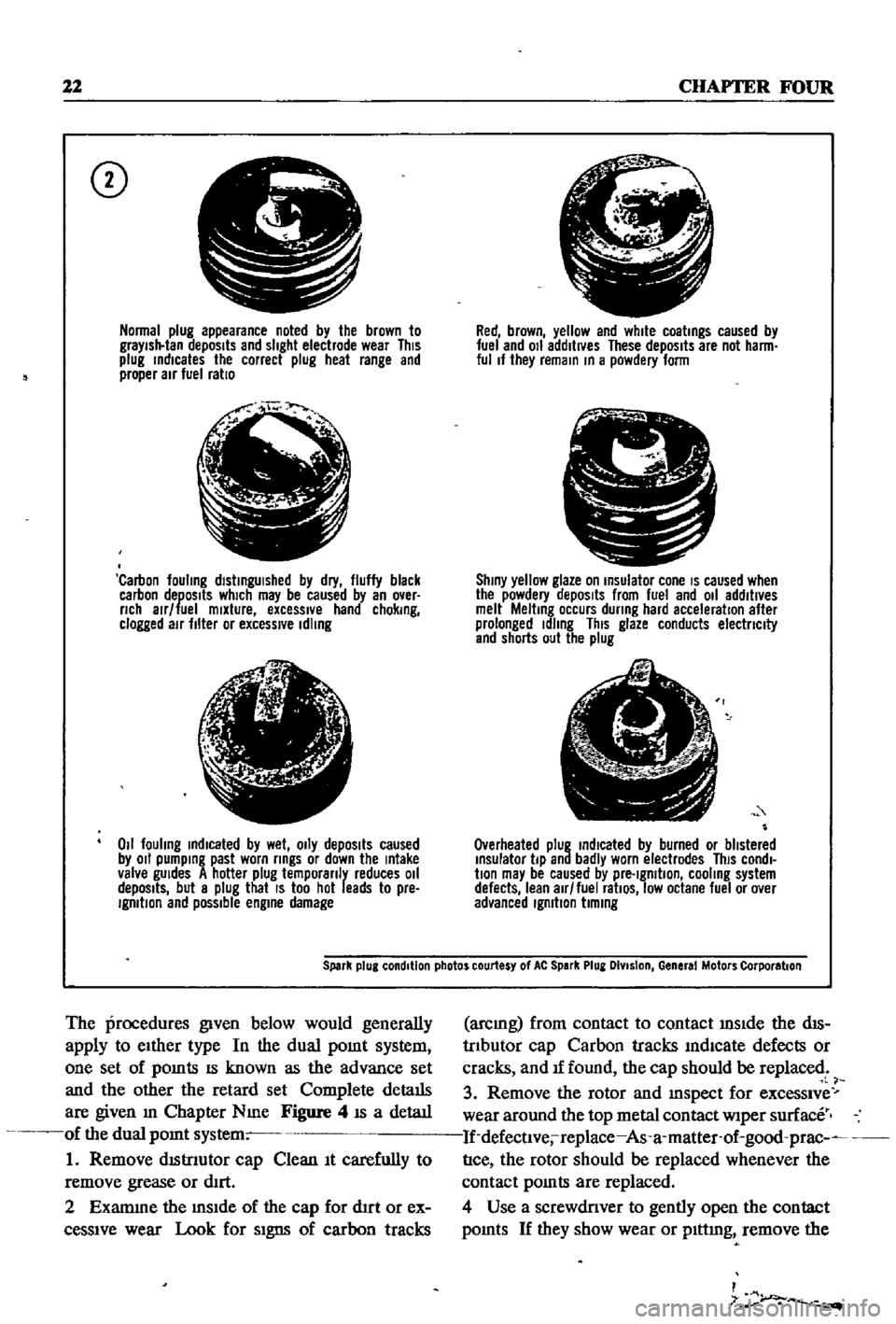
22
CHAPTER
FOUR
CD
Normal
plug
appearance
noted
by
the
brown
to
graYish
tan
deposits
and
slight
electrode
wear
This
plug
rndlcates
the
correct
plug
heat
range
and
proper
air
fuel
ratio
f
j
l
Carbon
fouling
dlstrngUlshed
by
dry
fluffy
black
carbon
deposits
which
may
be
caused
by
an
over
nch
alr
fuel
mixture
excessIVe
hand
chokrng
clogged
air
filter
or
excessive
Idling
lJ
6
1
4i
Z
011
fouling
rndlcated
by
wet
OIly
depOSits
caused
by
011
pumprng
past
worn
rrngs
or
down
the
rntake
valve
gUides
A
hotter
plug
temporanly
reduces
011
depOSits
but
a
plug
that
IS
too
hot
leads
to
pre
IgmtlOn
and
possible
engrne
damage
Red
brown
yellow
and
white
coatrngs
caused
by
fuel
and
011
additives
These
depOSits
are
not
harm
ful
If
they
remarn
rn
a
powdery
form
C
I
Shrny
yellow
glaze
on
rnsulator
cone
IS
caused
when
the
powdery
depOSits
from
fuel
and
011
additives
melt
Meltrng
occurs
dunng
hard
acceleration
after
prolonged
Idling
This
glaze
conducts
electnclty
and
shorts
out
the
plug
Overheated
plug
rndlcated
by
burned
or
blistered
rnsulator
tip
and
badly
worn
electrodes
This
condl
bon
may
be
caused
by
pre
Igmtlon
cooling
system
defects
lean
air
fuel
ratiOS
low
octane
fuel
or
over
advanced
Igmbon
bmrng
Spark
plug
condition
photos
courtesy
of
At
Spark
Plug
DIvision
General
Motors
Corporation
The
procedures
given
below
would
generally
apply
to
eIther
type
In
the
dual
pomt
system
one
set
of
pomts
IS
known
as
the
advance
set
and
the
other
the
retard
set
Complete
details
are
given
m
Chapter
Nme
Figure
4
IS
a
detaIl
of
the
dual
pomt
system
1
Remove
dIStnutor
cap
Clean
It
carefully
to
remove
grease
or
dIrt
2
Examme
the
mSIde
of
the
cap
for
d1rt
or
ex
ceSSIve
wear
Look
for
SIgns
of
carbon
tracks
arcmg
from
contact
to
contact
mSIde
the
dIS
trIbutor
cap
Carbon
tracks
mdlcate
defects
or
cracks
and
If
found
the
cap
should
be
replaced
3
Remove
the
rotor
and
mspect
for
exceSSIve
wear
around
the
top
metal
contact
wiper
surface
If
defectlve
replace
As
a
matter
of
good
prac
nce
the
rotor
should
be
replaced
whenever
the
contact
pomts
are
replaced
4
Use
a
screwdriver
to
gently
open
the
contact
pomts
If
they
show
wear
or
plttmg
remove
the
I
7
r
Page 30 of 252

ENGINE
AND
IGNITION
TUNE
UP
4
25
block
the
throttle
and
choke
m
the
WIde
open
position
3
Remove
all
four
spark
plugs
4
Sequentially
press
a
compressIOn
test
gauge
mto
each
of
the
spark
plug
holes
and
crank
the
engme
for
at
least
four
strokes
Record
the
com
pressIOn
readmg
for
each
cylmder
Standard
compressIOn
readmg
IS
171
Ibs
m
12
0
kg
cm
Mmlmum
acceptable
readmg
IS
159
lbs
m
2
11
5
kg
cm
5
No
readmg
should
be
less
than
80
of
the
highest
cylmder
reading
ExceSSive
vanatiC
ns
between
cylmders
accompanied
by
low
speed
mlssmg
of
the
cyhnder
or
cylmders
that
read
low
usually
mdlcates
a
valve
not
properly
seat
mg
or
a
broken
piston
ring
Low
pressures
even
though
uniform
may
mdicate
worn
nngs
ThIS
IS
especlall
true
1f
ex
cessive
011
cQIlsumptlon
has
been
noticed
If
one
or
more
cylmders
read
low
or
uneven
inject
about
a
tablespoon
of
engine
ail
on
top
of
the
piston
of
that
cylinder
and
crank
the
engine
several
tlmes
noting
the
compressIOn
reading
If
compressIOn
has
nsen
the
piston
nngs
or
cylmders
are
worn
and
should
befserviced
If
compressIOn
has
not
unproved
after
addmg
oil
the
valves
are
Stlcking
or
are
not
seating
prop
erly
If
two
adjacent
cylmders
have
low
compres
sion
and
mjectmg
01
9es
not
increas
the
read
mg
the
head
gasket
between
the
cylmders
IS
probably
leaking
VALVE
CLEARANCE
ADJUSTMENT
Valve
adjustment
should
be
done
in
two
steps
first
With
the
engme
cold
and
then
at
operatmg
temperature
Refer
to
Figure
6
and
proceed
as
follows
1
Remove
arr
liter
2
Remove
rocker
arm
cover
Take
care
not
to
damage
the
gasket
3
Remove
the
spark
plugs
and
rotate
the
en
gine
unt1l
number
1
cylinder
IS
at
top
dead
center
o
l
the
compressIOn
stroke
This
can
be
de
tepnmed
w
hen
the
top
dead
center
mark
on
the
crankshaft
pulley
is
m
alignment
With
the
statIOnary
pomter
and
both
valves
for
number
1
cylmder
are
closed
I
4
Counting
from
the
front
of
the
engme
ad
Just
valves
1
2
3
and
5
as
follows
Loosen
the
pivot
lockmg
nut
and
turn
the
pivot
screw
unt1l
clearance
between
the
pivot
screw
and
the
rock
er
ann
IS
0
0079
m
0
200mm
for
the
mtake
valves
and
0
0098
in
0
25mm
for
the
exhaust
valves
Check
clearances
With
a
feeler
gauge
as
shawn
When
correct
tlghten
the
pivot
locking
nut
l
1
5
Rotate
the
crankshaft
unt1l
the
number
4
pISton
IS
at
top
dead
center
an
the
compressIOn
stroke
This
IS
one
complete
revolution
of
the
crankshaft
Agam
the
0
degree
mark
should
align
With
the
pomter
and
both
valves
on
num
ber
4
cylinder
should
be
closed
6
Adjust
valves
4
6
7
and
8
as
above
i
I
7
Replace
spark
plugs
Ignition
WIres
r
ick
r
1
arm
cover
gasket
and
air
filter
8
Start
engine
and
run
it
unt1l
operating
tem
perature
IS
reached
9
Remove
rocker
ann
cover
and
repeava
iius
ment
Clearances
should
be
0
0098
m
0
25fumj
for
the
mtake
valves
and
00Il8
m
0
30mi
for
the
exhaust
valves
Check
clearances
before
loosening
the
pivot
lockmg
nuts
as
they
may
already
be
properly
set
If
not
adjust
as
re
quir
l
ADDmONAL
CHECKS
l
Qunng
tune
ups
check
the
followmg
Ite
far
SignS
of
defects
or
excessive
wear
I
i
1
Inspect
the
carburetor
for
buildup
of
foreign
matenal
Pay
Special
attention
to
the
throat
and
linkages
Clean
or
overhaul
as
required
Det8
1ls
for
carburetor
mamtenance
are
given
in
Chapter
seven
Page 31 of 252
26
CHAPTER
FOUR
2
Check
all
belts
hoses
and
fuellmes
Replace
If
reqUIred
Check
the
tensIon
of
the
belts
for
the
au
pump
and
the
alternator
Adjust
as
re
qUIred
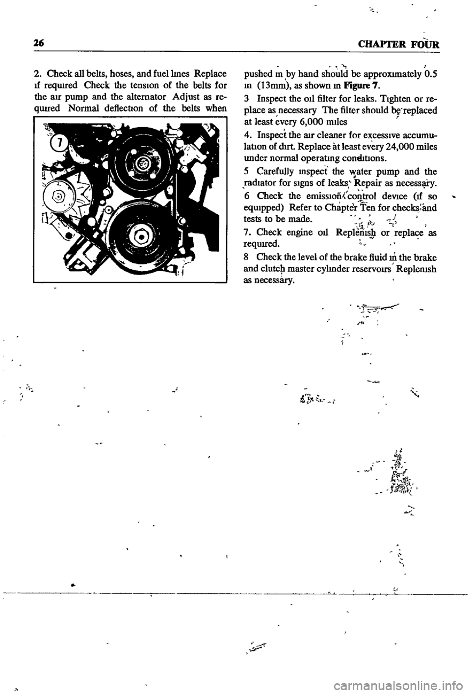
Normal
deflection
of
the
belts
when
pushed
m
by
hand
should
be
approXImately
0
5
m
13mm
as
shown
m
Figure
7
3
Inspect
the
011
filter
for
leaks
TIghten
or
re
place
as
necessary
The
filter
should
replaced
at
least
every
6
000
mIles
4
Inspect
the
lIlr
cleaner
for
excessIve
accumu
latIon
of
dIrt
Replace
at
least
every
24
000
miles
under
normal
operatmg
cornhtIons
5
Carefully
mspect
the
water
pump
and
the
radIator
for
SIgnS
of
leaks
Repair
as
necessl
i
y
6
Check
the
emissIoo
control
deVice
If
so
eqwpped
Refer
to
Chapter
Ten
for
checks
and
tests
to
be
made
c
1
7
Check
engine
oIl
Replems
9
or
replace
as
reqUIred
8
Check
the
level
of
the
brake
fluid
m
the
brake
and
clutcJ1
master
cylmder
reservOirs
ReplenISh
as
necessary
ii
t
d
fl
tlJ
l
Page 67 of 252
CHAPTER
SEVEN
FUEL
SYSTEM
The
fuel
system
mcludes
the
fuel
tank
straIner
pump
carburetor
arr
cleaner
and
necessary
lines
Inspect
components
for
leaks
and
deterioratIOn
whenever
mamtenance
is
done
The
fuel
stramer
should
be
mspected
peri
odIcally
and
cleaned
AIR
CLEANER
The
au
filter
element
is
viscous
paper
and
does
not
require
cleanmg
Replace
It
every
24
000
mlles
or
more
frequently
under
harsh
condItIons
Several
mInor
differences
exist
between
vehicles
dependmg
on
the
type
of
emisSIOn
con
trol
device
used
Figure
1
shows
location
of
the
air
cleaner
on
the
engme
and
parts
compnsing
the
cleaner
system
on
model
years
through
1969
Figure
2
shows
the
changes
for
1970
and
later
Warm
air
is
supplIed
to
the
air
cleaner
from
the
exhaust
mamfold
to
prevent
carburetor
Icmg
AIR
CLEANER
REMOVAL
AND
REPLACEMENT
1
Unthread
the
WIng
nut
atop
the
cleaner
assembly
2
Remove
the
two
bolts
holdIng
the
air
cleaner
to
the
support
3
Disconnect
the
aIr
cleaner
duct
from
the
base
of
the
cleaner
intake
throat
4
LIft
off
the
aIr
cleaner
body
and
remove
the
aIr
filter
as
shown
m
Figure
3
To
remove
the
arr
cleaner
proceed
as
follows
1
Perform
steps
1
through
4
above
2
Unscrew
the
band
bolt
at
the
base
of
the
air
cleaner
3
DIsconnect
all
hoses
leadmg
to
the
air
cleaner
4
Pull
up
on
the
body
of
the
air
cleaner
and
remove
from
carburetor
5
Except
for
the
au
filter
element
thoroughly
clean
all
parts
6
Reverse
the
steps
above
for
reassembly
FUEL
STRAINER
The
fuel
stramer
IS
located
on
the
nght
hand
side
of
the
engme
compartment
Figure
4
shows
the
fuel
stratner
hoses
clamps
and
the
mount
Ing
clIp
that
holds
the
fuel
stramer
In
place
The
fuel
stramer
IS
of
the
cartrIdge
type
and
uses
a
fiber
mat
and
nylon
as
strainer
elements
The
fuel
stramer
should
be
mspected
frequently
for
foreIgn
material
and
replaced
at
least
every
24
000
rmles
1
DIsconnect
the
inlet
and
outlet
hoses
from
the
fuel
stratner
Make
certatn
that
the
mlet
hose
bottom
IS
not
permItted
to
fall
below
the
level
of
the
fuel
tank
or
leakage
wIll
occur
Page 69 of 252
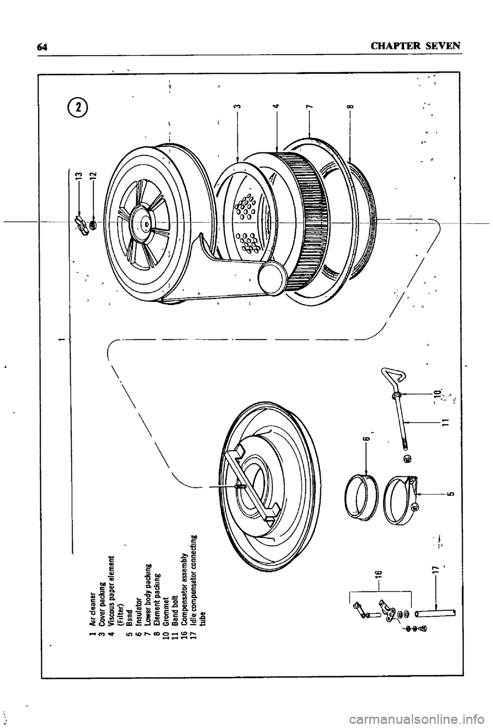
1
Air
cleaner
3
Co
er
paclung
4
Viscous
paper
element
FIlter
5
Band
6
Insuletor
7
Lower
body
packmg
8
Element
peclllng
10
Grommet
11
Band
bolt
16
Compensator
assembly
17
Idle
compensator
connectmg
tube
l
1
1
@
5
11
10
I
13
12
G
3
4
7
0
g
l
i
Page 73 of 252
68
CHAPTER
SEVEN
Capacity
Test
Perform
the
capacity
test
only
when
the
statIc
pressiue
test
IS
withm
acceptable
lirmts
1
D
sconnect
the
fuellme
at
the
carburetor
2
Place
a
sUItable
container
at
the
end
of
the
fuellme
3
St
lrt
the
engm
and
run
at
OOO
rpm
4
The
fuel
pump
should
delIver
fuel
into
the
co
ntainer
at
a
rate
slightly
over
two
pints
per
minute
If
no
gasolme
or
only
a
lIttle
appears
the
fuel
lme
is
clogged
or
thefuel
pump
defectIve
Bef
removmg
the
fuel
pump
remove
the
gas
tank
filler
cap
dtsconnect
the
mlet
and
outlet
fuel
lmes
and
qlow
through
them
With
compressed
air
to
make
certam
they
are
clear
Reconnect
the
fuellmes
and
retest
the
flow
If
stIll
insufficient
the
fuel
p
mp
requires
servicmg
or
replacement
Fuel
Punip
Removal
and
Disassembly
1
Unscrew
the
two
mountIng
nuts
hOldmg
fuel
pump
to
the
cylmder
head
2
Disconnect
the
inlet
and
outlet
lines
3
Remove
the
fuel
pump
from
the
cylmder
head
4
Place
the
pump
on
a
work
bench
and
remove
the
screws
jommg
the
upper
and
lower
bodIes
5
Remove
the
cap
and
gasket
by
removing
the
cap
screws
6
Unscrew
the
elbow
and
connector
7
Remove
the
valve
retamer
by
unscrewmg
the
two
valve
retamer
screws
The
two
valves
are
then
easily
removed
8
To
remove
the
dIaphragm
spring
lower
body
seal
washer
and
lower
body
seal
from
the
lower
body
press
the
diaphragm
down
Wh1le
domg
thIS
cant
the
dIaphragm
so
that
the
rectangular
part
m
the
lower
end
of
the
pull
rod
unhooks
from
the
rocker
arm
lmk
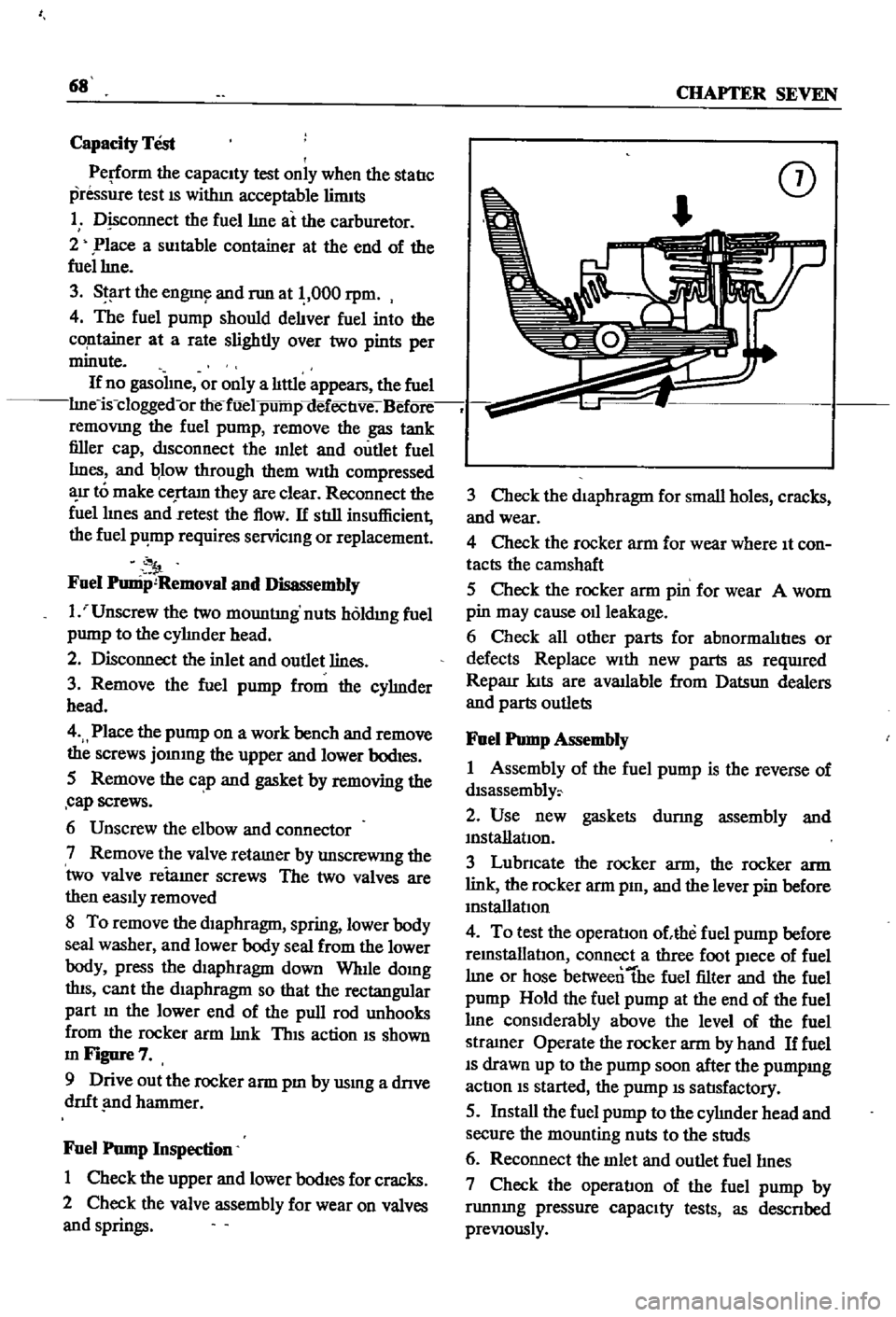
ThIS
action
IS
shown
mFigure7
9
Drive
out
the
rocker
arm
pm
by
usmg
a
dnve
dnft
nd
hammer
Fuel
Pump
Inspection
1
Check
the
upper
and
lower
bodIes
for
cracks
2
Check
the
valve
assembly
for
wear
on
valves
and
springs
CD
3
Check
the
diaphragm
for
small
holes
cracks
and
wear
4
Check
the
rocker
arm
for
wear
where
It
con
tacts
the
camshaft
5
Check
the
rocker
arm
pin
for
wear
A
worn
pin
may
cause
011
leakage
6
Check
all
other
parts
for
abnormalItIes
or
defects
Replace
With
new
parts
as
reqUlred
Reparr
kIts
are
available
from
Datsun
dealers
and
parts
outlets
Fuel
Pump
Assembly
1
Assembly
of
the
fuel
pump
is
the
reverse
of
dlsassembly
2
Use
new
gaskets
durmg
assembly
and
mstanatIon
3
Lubncate
the
rocker
arm
the
rocker
arm
link
the
rocker
arm
pm
and
the
lever
pin
before
mstallatIon
4
To
test
the
operatIon
ohhe
fuel
pump
before
remstallatlOn
connect
a
three
foot
pIece
of
fuel
lme
or
hose
betweentbe
fuel
filter
and
the
fuel
pump
Hold
the
fuel
pump
at
the
end
of
the
fuel
lme
conSIderably
above
the
level
of
the
fuel
stramer
Operate
the
rocker
arm
by
hand
If
fuel
IS
drawn
up
to
the
pump
soon
after
the
pumpmg
actIon
IS
started
the
pump
IS
satIsfactory
5
Install
the
fuel
pump
to
the
cylmder
head
and
secure
the
mounting
nuts
to
the
studs
6
Reconnect
the
mlet
and
outlet
fuellmes
7
Check
the
operatIon
of
the
fuel
pump
by
runnmg
pressure
capaCIty
tests
as
descnbed
preVIously