1968 DATSUN 510 tires
[x] Cancel search: tiresPage 10 of 252
GENERAL
INFORMATION
5
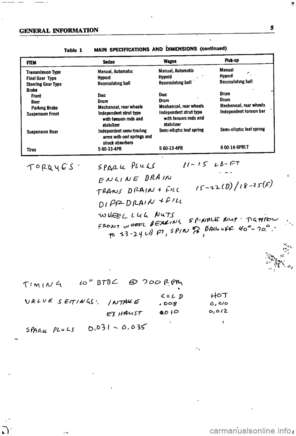
Table
1
MAIN
SPECIFICATIONS
AND
DIMENSIONS
continued
Suspension
Rear
Sedan
Wagon
Pick
up
Manual
Automatic
Manual
Automatic
Manual
HypoJd
Hypoid
Hypold
ReCIrculating
ball
ReCIrculating
ball
ReCirculating
ball
DIsc
DIsc
Drum
Drum
Drum
Drum
Mechanical
rear
wheels
Mechanical
rear
wheels
Mechanical
rear
wheels
Independent
strut
type
Independent
strut
type
Independent
torsion
bar
with
tension
rods
and
with
tension
rods
and
stabilizer
stabilIZer
Independent
semi
trailing
Semi
elliptiC
leaf
spring
Semi
elliptic
leaf
spnng
arms
wrtII
coli
springs
and
shock
absorbers
5
6O
13
4PR
5
6O
13
4PR
600
14
6PRLT
ITEM
Transmission
Type
Final
Gear
Type
Steering
Gear
Type
Brake
Front
Rear
Parking
Brake
Suspension
Front
Tires
6
2
Q
1
C
S
PA
l
PlLlU
EN
4
1
AJ
E
Dt7
A
1
1
1
2
A
ru
r
f
f
A
I
III
r
c
o
I
pP
D
LA
I
tV
r
IL
c
W
L
L
l
G
ftiv
TJ
dE
IJ
S
prlc
I
u
F
l
e
p
f
vi
Ii
ftl
1
3
l
1t
J
p7
5
PrlV
B4dc
u
11
1
S
t
f
PT
f
L
UJ
ff
zr
F
T
ff
lfo
1oo
4
t
M
0
IY
AJ
to
BTOL
@
OD
2
lP
S
PAtl
pI
c
5
IN
G
ex
Sf
0103
I
D
0
3
O
j
oo
0
0
0
to
l
c
o
0
0
2
JP
t
UE
SEIT
A
C
1
J
Page 11 of 252
CHAPTER
TWO
PERIODIC
MAINTENANCE
To
ensure
good
performance
dependability
and
safety
regular
penodlc
maintenance
is
necessary
TIns
chapter
outlInes
routine
and
penodlc
mamtenance
for
the
average
dnver
Under
heavy
usage
semcmg
mtervals
will
be
shortened
Regular
routme
mamtenance
will
help
aVOId
expensive
repaIrs
ROUTINE
CHECKS
The
followlDg
checks
should
be
performed
at
each
fuel
stop
1
Check
engme
oil
level
Top
up
as
requrred
2
Check
radiator
coolant
level
Top
up
as
re
qwred
3
Check
battery
electrolyte
The
battery
case
IS
marked
With
upper
hrmt
and
lower
lnmt
lInes
Level
should
be
maID
tamed
between
the
IIDes
4
Check
that
the
master
cylInder
brake
flwd
reservOir
level
IS
between
the
max
and
mm
lInes
marked
on
the
plastic
case
S
Check
the
plastic
clutch
cyhnder
reservoir
level
Level
should
be
between
the
max
and
mm
lInes
6
Check
the
windsh1eld
washer
flwd
reservoir
Top
up
as
required
7
Check
tire
pressures
when
the
tIres
are
cold
Front
and
rear
tire
pressures
should
be
24
pounds
under
normal
dnving
conditions
TIre
pressure
should
be
28
pounds
for
h1gh
speed
dnvmg
conditions
8
Check
the
engIne
for
general
conditIon
Check
for
leaky
or
cracked
hoses
and
loose
wmng
9
Check
condition
of
wmdshleld
wiper
blades
PERIODIC
CHECKS
Table
1
prOVIdes
penodIc
checks
and
main
tenance
that
should
be
performed
on
a
set
schedule
Table
2
gIves
recommended
lubncants
and
Table
3
specIfies
the
grades
of
oil
that
should
be
used
Procedures
for
performmg
the
semces
are
presented
ID
vanous
chapters
of
tlus
manual
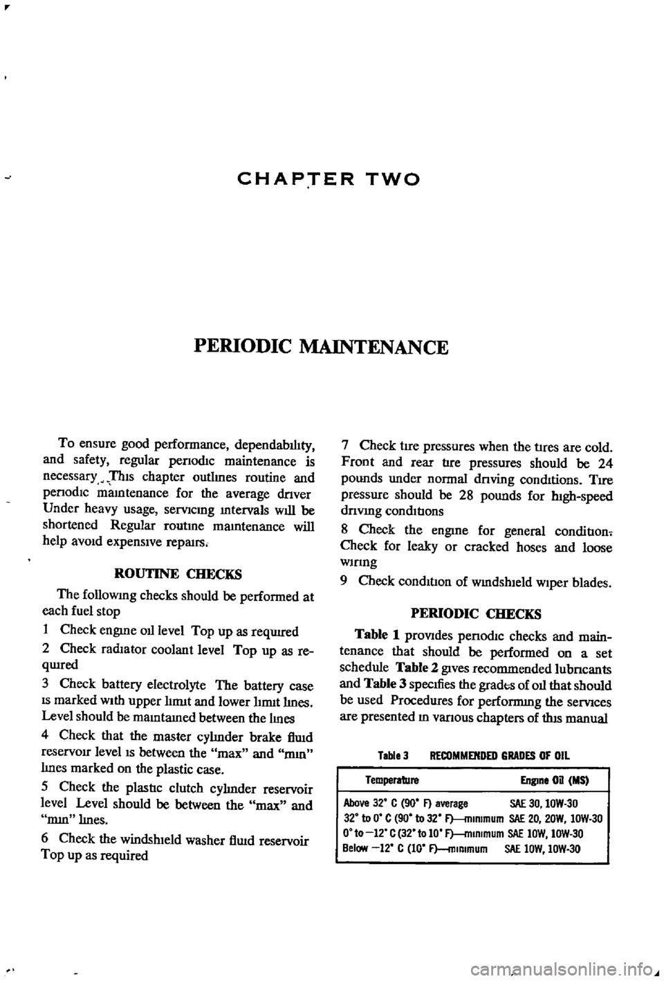
Table
3
RECOMMENDED
GRADES
OF
OIL
Temperature
Engine
on
MS
Above
32
C
90
F
average
SAE
30
IOW
30
32
to
0
C
90
to
32
F
mlmmum
SAE
20
20W
IOW
30
O
to
12
C
32
tolO
F
mlRlmum
SAE
IOW
IOW
30
Below
12
C
10
F
mlmmum
SAE
lOW
IOW
30
Page 21 of 252
16
CHAPTER
TIlREE
sary
Also
check
all
parts
for
mlSaltgnment
and
uneven
wear
TRANSMISSION
1
Difficult
to
mesh
gears
Make
certam
the
clutch
pressure
plate
and
re
lease
beanng
are
m
good
condItion
The
trouble
can
be
caused
by
worn
gears
shaft
and
or
bear
mgs
DISassemble
and
repaIr
as
requIred
Also
can
be
caused
by
msufficlent
operatmg
stroke
due
to
worn
or
loose
sltdmg
parts
or
a
defective
synchronIZer
DIsassemble
carefully
InSpect
and
replace
as
requIred
2
Gears
slip
out
of
mesh
Generally
thIS
trouble
occurs
when
the
mterlock
plunger
check
ball
and
or
spnng
IS
weakened
or
worn
The
trouble
can
also
be
caused
by
worn
fork
rod
ball
groove
damaged
bearings
or
dam
aged
gears
DIsassemble
carefully
mspect
and
replace
as
required
3
NOIse
If
nOISes
are
heard
wIth
the
engme
idlmg
and
the
clutch
disengaged
the
nOIse
IS
probably
conung
from
the
transmISSIOn
Several
Items
can
cause
nOISes
either
smgly
or
m
combmatIon
Check
the
qualIty
and
quantity
of
lubrIcant
in
the
trans
mISSIon
Replace
or
replenISh
as
necessary
Worn
bearIngs
wIll
usually
produce
a
lugh
humming
at
hIgh
speed
and
a
cycltc
knockIng
sound
at
low
speed
Worn
or
damaged
splInes
and
bushmgs
will
also
cause
nOIse
BRAKES
1
Brake
pedal
goes
to
floor
There
are
numerous
causes
for
thIS
includIng
excessIvely
worn
Itnmgs
aIr
in
the
hydraultc
sys
tem
leaky
brake
lmes
leaky
wheel
cylmders
or
leaky
or
worn
master
cylmder
Check
for
leaks
and
thIn
brake
linmgs
Bleed
and
adjust
the
brakes
If
thIS
doesn
t
cure
the
trouble
rebwld
wheel
cylmders
a
nd
or
master
cylmder
2
Spongy
pedal
Normally
caused
by
aIr
m
the
system
blee
d
and
adjust
the
brakes
3
Brakes
pull
Check
brake
adjustment
Also
check
for
contam
inated
brake
Itmngs
from
leaks
leaky
wheel
cyltnders
loose
caltpers
frozen
or
seIZed
pIstons
and
restrIcted
brake
lmes
or
hoses
In
addItion
check
front
end
alignment
and
suspensIOn
dam
age
such
as
broken
front
or
rear
sprmgs
shocks
etc
Check
condItIon
of
tIres
4
Brakes
squeal
or
chatter
Check
brake
lmmg
thickness
and
brake
drum
roundness
Ensure
that
the
shoes
have
cham
ferred
ends
and
are
not
loose
Inspect
the
condI
tion
of
the
rotors
on
the
front
wheel
dISC
brakes
to
make
certain
they
are
not
scored
or
damaged
Clean
away
all
dIrt
on
shoes
pads
rotors
or
drums
5
Draggmg
brakes
Check
brake
adjustment
includmg
handbrake
Check
for
broken
or
weak
shoe
return
springs
swollen
rubber
parts
due
to
unproper
brake
flUId
or
other
contammatIon
Clean
or
replace
de
fectIve
parts
6
Hard
pedal
Check
brake
linmgs
for
contammation
Also
check
for
restrIcted
brake
lines
and
hoses
7
High
speed
fade
Check
for
dIstorted
or
out
of
round
drums
and
contamInated
brake
lmmgs
Make
certam
the
recommended
brake
flUId
IS
used
Dram
entIre
system
and
refill
If
In
doubt
8
Pulsatmg
pedal
Check
for
dIStorted
or
out
of
round
drums
or
rotors
Check
for
excessIVe
brake
dISC
run
out
STEERING
AND
SUSPENSION
NOTE
Unusual
steermg
pullmg
or
wandermg
IS
usually
caused
by
bent
or
otherwise
mIsaligned
suspenszon
parts
Because
of
the
speCialized
equIp
ment
reqUired
to
evaluate
and
correct
these
faults
It
IS
recommended
t
tat
servIce
to
the
steermg
and
suspension
system
be
referred
to
your
Datsun
dealer
oca
quallfied
specrallst
m
thiS
field
1
VibratIOn
felt
m
steermg
wheel
VIbratIon
can
be
caused
by
several
thmgs
includ
ing
lll1proper
aIr
pressure
m
tIres
uneven
wear
Page 23 of 252
18
CHAP1
lER
THlREE
c
c
c
ce
J
1
Ii
j
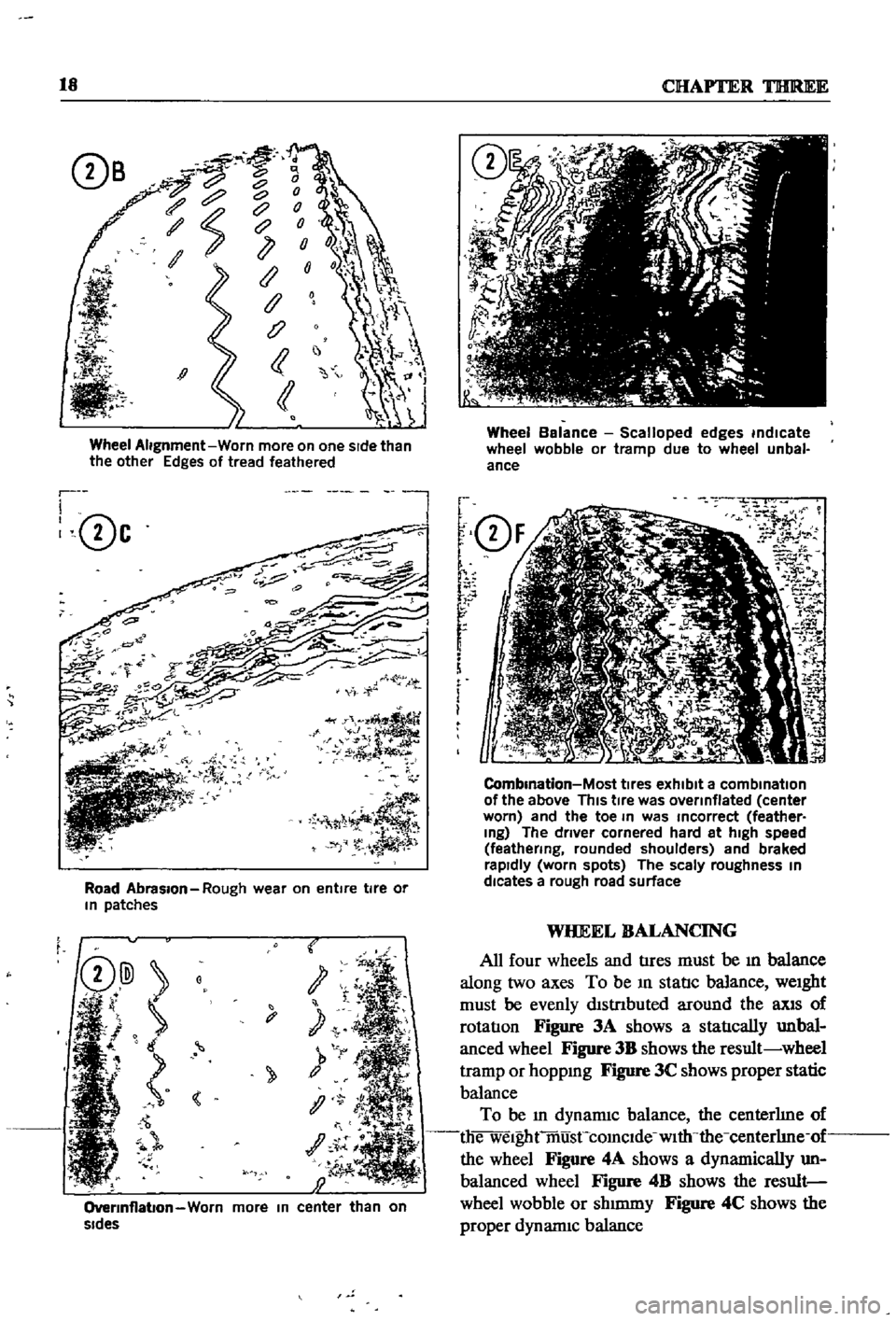
Wheel
Alignment
Worn
more
on
one
sIde
than
the
other
Edges
of
tread
feathered
r
I
0c
l
Road
Abrasion
Rough
wear
on
entire
tire
or
In
patches
t
y
1
OverInflabon
Worn
more
In
center
than
on
sides
Wheel
Balance
Scalloped
edges
indicate
wheel
wobble
or
tramp
due
to
wheel
unbal
ance
f
Q
F
r
r
r
f
i
m
i
O
2
7
iK
J
1
J
i
i
5J
CombInation
Most
tIres
exhibit
a
combination
of
the
above
This
tIre
was
overinflated
center
worn
and
the
toe
In
was
Incorrect
feather
Ing
The
driver
cornered
hard
at
high
speed
feathering
rounded
shoulders
and
braked
rapidly
worn
spots
The
scaly
roughness
In
dlcates
a
rough
road
surface
WHEEL
BALANCING
All
four
wheels
and
tIres
must
be
ill
balance
along
two
axes
To
be
ill
statIc
balance
weight
must
be
evenly
dlstnbuted
around
the
llXlS
of
rotatIon
Figure
3A
shows
a
statIcally
unbal
anced
wheel
Figure
3B
shows
the
result
wheel
tramp
or
hoppmg
Figure
3C
shows
proper
static
balance
To
be
ill
dynamiC
balance
the
centerhne
of
die
welghtmusCcomclde
with
the
centerhne
of
the
wheel
Figure
4A
shows
a
dynamically
un
balanced
wheel
Figure
4B
shows
the
result
wheel
wobble
or
shmuny
Figure
4C
shows
the
proper
dynannc
balance
Page 245 of 252
l
INDEX
239
Rear
suspensIOn
wagon
Removal
40
92
Servlcmg
161
Termmals
94
Tightening
torques
162
Test
diagnosIs
97
Testmg
96
Troubleshootmg
10
5
Steenng
also
see
Suspension
front
I
Exploded
views
182
185
L
Seats
SpecIfications
186
DescnptIon
228
Troubleshooting
16
Exploded
View
front
4
door
sedan
232
SuspensIOn
front
pick
up
Exploded
VIew
front
pick
up
228
Axle
removal
175
Service
hmts
4
Inspection
and
repair
179
Shock
absorbers
sedan
154
Installation
179
Shock
absorbers
wagon
162
Posture
adjustment
181
Spark
plugs
Removal
177
CondlllOn
chart
21
Wheel
abgnment
182
InspectIon
and
servlcmg
21
Wheel
bearmg
adjustment
177
Recommended
types
112
Suspension
front
sedan
and
wagon
SpecificatIOns
and
tables
Inspection
and
repair
176
Adjustment
and
wheel
alignment
175
InstallatIOn
177
Brake
service
data
203
204
Lower
ball
Jomt
174
Brakes
203
204
Spnng
and
strut
assembly
173
Camshaft
beanngs
48
Stabilizer
173
Caster
and
camber
sedan
and
wagon
175
TenSIOn
rod
173
Clutch
134
Transverse
bnk
174
Clutch
service
data
134
Wheel
beanngs
177
Connectmg
rod
beanng
underslzes
52
Wheel
hubs
and
bearmgs
168
173
Dlstnbutor
112
SWItches
Dnveshaft
147
DescnptIon
205
Dnveshaft
service
dala
147
Exploded
View
through
1969
208
Engme
60
61
Exploded
view
1970
1972
207
Engme
service
data
60
61
General
4
Mam
bearmg
underslzes
52
T
Piston
rmg
gap
50
Rear
suspenSIOn
pick
up
167
Tail
gate
228
233
Rear
suspensIOn
torques
wagon
162
TenSIOn
rod
sedan
and
wagon
173
Steermg
186
Thermostat
TransmiSSion
manual
144
DescnptIon
89
TransmiSSion
service
data
manual
144
Inspection
and
replacement
89
Valve
spnng
47
Removal
89
Sprmg
and
strut
assembly
sedan
and
wagon
173
Tires
Spnngs
sedan
154
Wear
analYSIS
17
Stabilizer
sedan
and
wagon
173
TransmiSSion
automatic
Starter
Downshift
solenOid
147
Armature
95
Inhlbllor
SWItch
148
Beanngs
96
Kick
down
SWitch
147
Brush
holder
96
Lmkage
mspectIon
and
adjustment
148
Brushes
and
lead
WIre
95
011
checks
147
Cleaning
mspectIon
and
repair
94
Oil
leakage
147
Construcllon
92
TransmiSSion
manual
Disassembly
92
DescnptIon
134
Exploded
View
93
Disassembly
138
Field
COIl
94
Exploded
view
138
Magnetic
SWItch
96
Gear
assembly
exploded
view
139
Magnetic
SWItch
assembly
test
97
Inspection
and
repair
141
Operation
91
Installation
143
Overrunnmg
clutch
96
Reassembly
and
adjustment
142
Reassembly
96
Removal
134